
Abstract
Changes in temperature and stress will lead to the rail creeping of high-speed railway, which becomes a hidden danger in the operation of trains. This paper studies a real-time visual measurement system for creeping displacement monitoring. The bilateral line extraction to determine the target location overcomes the influence of ambient light on image grayscale. The dynamic region of interest setting method is produced to lock and track the target. The self-calibration technology makes the system suitable for field application. The remote transmission of monitoring data is realized through narrow band internet of things (NB-IOT). These methods solve the problems in practical application. The monitoring system provides a reliable guarantee for the safe and stable operation of high-speed railway.
Introduction
Rail creeping, also known as railway line creeping, is a kind of longitudinal creeping phenomenon along the railway. The main causes of rail creeping are the longitudinal force during train operation and the stress caused by the changes in rail’s temperature.1–4 With the increase in railway transportation tasks, the impact of the train wheels on the rails during operation accelerates the creeping of the rail. Especially for high-speed railway, which consists of a large number of seamless rails to eliminate the joints, the rails cannot freely expand or contract. Excessive temperature change, stress and displacement will cause the seamless rail to expansion or even fracture, which will impair transportation safety.
According to the statistics, more than 80 track swelling accidents occurred during the operation of French high-speed railways from 1993 to 2001. The break-down of Saldanha iron ore railway caused huge economic losses to Spoornet. In 2009, a rail in the xiang-ling section of China Shanghai–Kunming railway suddenly broke, which was discovered by the staff in time, thus avoiding a possible major accident. 5 It can be seen that the monitoring of rail creeping displacement is of great significance for ensuring the safe operation of high-speed railway.
The traditional measurement methods of creeping displacement include artificial drawing, contact measurement and laser observation. The artificial drawing method is time-consuming and laborious, and its accuracy is not also high, which affects the efficiency of railway transportation. The contact sensor is adopted in the contact measurement method, which has higher requirements on the sensor installation. The high-speed running of train will greatly interfere with measurement and reduce the service life of the sensor. The laser observation method also needs the operation of observer in measurement process, which brings personnel error factors accordingly.6,7
In view of the foregoing situation, this paper studies a rail displacement monitoring device based on machine vision. The device can monitor the rail displacement in real time and, aimed at the actual situation of the railway, realize remote monitoring through the data transmission technology of Internet of Things. The rail state of each distributed monitoring point can be timely grasped to achieve early warning of hazards, providing a guarantee for the safe operation of high-speed railway.
System structure and principle
The system adopts the principle of visual measurement and consists of a target and a monitoring instrument. It need not to install any equipment on the rail except to spray the target on the waist of the rail, that has no any impact on the train. The monitoring instrument is fixed on railway observation pile. It acquires the target image through the imaging lens and the camera and monitors the displacement of the target through image recognition, which is exactly the longitudinal displacement of the rail, as shown in Figure 1(a). The target consists of equidistant squares with a spacing of 10 mm. This design facilitates the self-calibration of the monitoring instrument on filed. The target is shown in Figure 1(b).
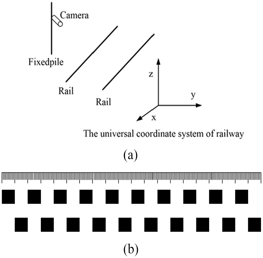
Monitoring device layout and target: (a) Schematic diagram of monitoring device layout. (b) Monitoring target.
The composition of monitoring instrument is shown in Figure 2. The main control chip of this system adopts IMX6Q, which has Cortex-A9 quad-core processor architecture. It is very suitable for quickly processing a large number of image matrix data and has two-dimensional (2D) and three-dimensional (3D) graphics acceleration interface, which can provide a faster computing environment for OpenCV.8,9 In this paper, the image processing algorithms are just based on this platform. The lens is combined with the charge-coupled device (CCD) camera to capture the target image. In the case of night monitoring, the lighting is activated by the main control circuit through photosensitive resistor. When the train passes through the monitored rail, the force of train to the rail will cause intermittent vibration of the rail, which is an interference factor for image acquisition. Therefore, the system integrates a vibration sensor to judge if the train passes, and then, the system will avoid this situation during image collection. The system also integrates the rail temperature sensor to acquire the temperature data and facilitate the subsequent data analysis.
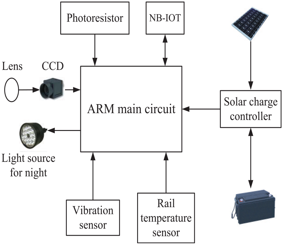
The block diagram of system structure.
The NB-IOT data communication module built into the measurement system can connect to the GSM-, TD-SCDMA- and TD-LTE-type carrier network,10,11 and the data can be directly transmitted back to the main station through the 4G Modem with built-in SIM card. That has no distance restrictions, only needs a small monthly rent and flow costs. It saves a lot of labor and time costs and gets real-time information. Due to the field application of the system, it is powered by solar energy and is equipped with a lead–acid battery to store electrical energy and provides power for the system.
The rail creep mainly means longitudinal displacement, and the horizontal displacement cannot be considered. According to the design requirements, the monitoring longitudinal range X is 250 mm, and the resolution is 0.1 mm. Therefore, for the selection of camera, the longitudinal pixel should be bigger than 2500. In this paper, the selected camera has 5 million, namely, 2592 × 1944 pixels. According to the imaging formula (1)
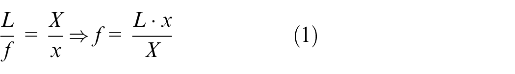
where L is the object distance, f is the focal length, X is the monitoring range and x is the width of planar CCD; it can be seen that a small-sized CCD can reduce the focal length. Since the object distance L is about 6 m, a 1/4″ CCD is selected, which has a size of 3.2 mm × 2.4 mm. For the selection of the lens, according to formula (1), the focal length f should be 76.8 mm, so the focal length of the selected lens is 75 mm.
Dynamic region of interest setting method
The whole image processing mainly includes image acquisition, grayscale transform, image filtering, region of interest (ROI) setting, threshold segmentation, line extraction and parameter calculation. The entire algorithm is based on the embedded OpenCV, which is an open source visual image processing function library. It provides basic function support for the whole algorithm and is transplanted into IMX6Q for software development. The image processing flow is shown in Figure 3.
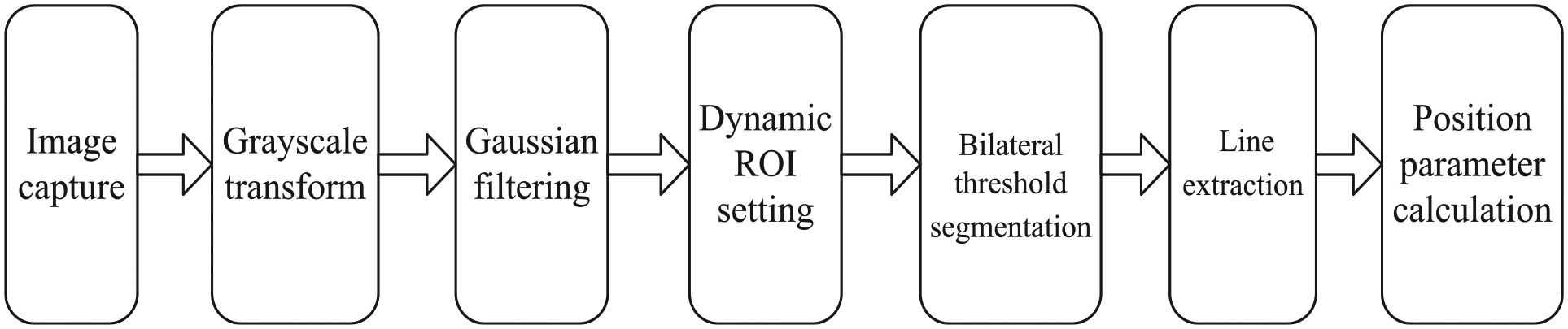
Image processing process.
The acquired image is converted into a grayscale image, and Gaussian filtering is performed to remove noise interference. Then, the image processing area is set by ROI to improve calculation efficiency. Bilateral threshold segmentation is performed in the ROI setting region, and the lines on both sides are extracted in the monitored target “square.” Through the compensation calculation, we can obtain the pixel at the center of the “square” and monitor its position change, that is, just the rail displacement.
A number of rectangular squares are distributed in the target, as shown in Figure 1(b), so the first step of image detection process should be to select one of the squares as a monitoring target and then monitor its position changes. It requires rectangular recognition during the initial image processing, filtering by rectangular area, and selecting a “square” located in the middle of CCD view field for monitoring, as shown in Figure 4.
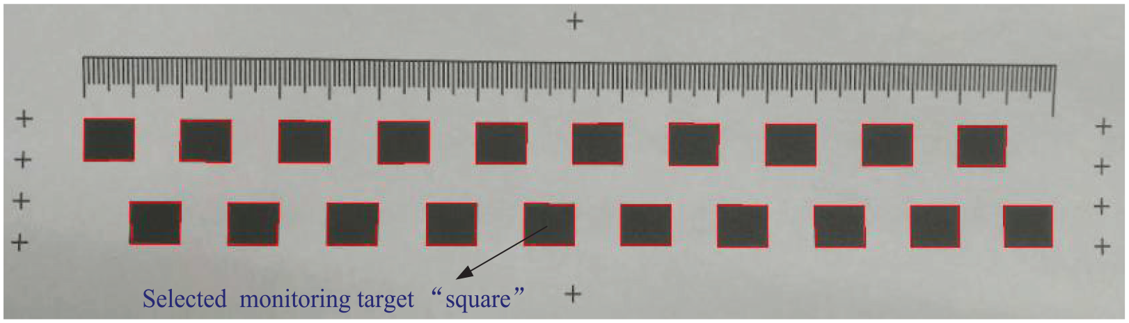
Monitoring target selection.
Then, the center position of the target “square” could be detected and calculated. With this position as its center, the ROI area for the next detection should be expanded around to cover the target “square.” The threshold segmentation and line extraction of the target “square” are performed in this newly setting ROI region for the next acquired image. Then, the ROI region is reset according to the above principle for the next measurement. In such a continuous cycle, it can be seen that the setting of the ROI is not fixed but changes with the location of the target “square,” forming the effect of continuous target tracking, as shown in Figure 5.
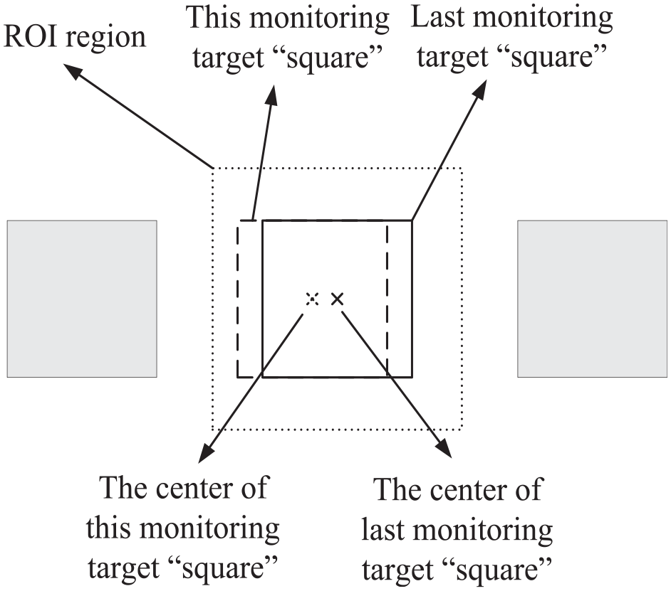
Dynamic ROI setting.
Since the rail creeping is a process of slow change, 3 during the interval of two adjacent image acquisition and processing, the creeping displacement does not cause the target “square” to jump out of the setting ROI region, which ensures that the same target is always monitored.
Bilateral threshold segmentation and line extraction algorithm
In the whole image processing, a key issue is to extract the edge line of target “square” after threshold segmentation. As the captured image is easy to be affected by the change of illumination, its grayscale also changes accordingly. The traditional method of extracting a single side line to determine the position of the square will bring a large degree of random error. Therefore, this paper proposes the bilateral threshold segmentation and line extraction method, which greatly reduces the random error in the measurement process and improves the measurement accuracy.
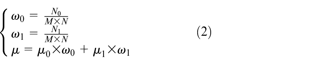
For the threshold segmentation, it adopts an adaptive threshold determination method (OSTU method).12–14 The classification principle of this algorithm is to maximize the inter-class variance between the background and the target because the greater the inter-class variance, the greater the difference between the background and the foreground of image. Let the image be I (x, y), its size be M × N and the segmentation threshold of the foreground (i.e. target) and the background be recorded as T. The proportion of pixels belonging to the foreground in the whole image is
It can be concluded that the inter-class variance is

It can be derived by calculation

Then, the traversal method is adopted to find the maximum value of inter-class variance g, which is exactly the segmentation threshold value.
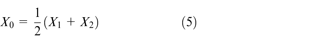
This paper extracts the both side lines of the target “square” based on the OSTU method. The center position of the target “square” can be determined through the compensation calculation of the left and right positions, so as to eliminate the influence of illumination change on the image grayscale. The center position change of the target “square” is exactly the rail displacement change. We assume the left line position is X1 and the right line position is X2; thus, the center position X0 is
The illumination change produces an error
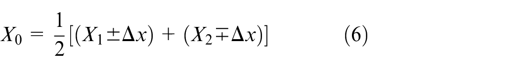
It can be seen that the center position is unchanged, which eliminates the influence of random error. The schematic diagram is shown in Figure 6(a). The actual target is processed as shown in Figure 6(b). The coordinates of the two sides are obtained by the above method, and then, the coordinate of the center point is determined.
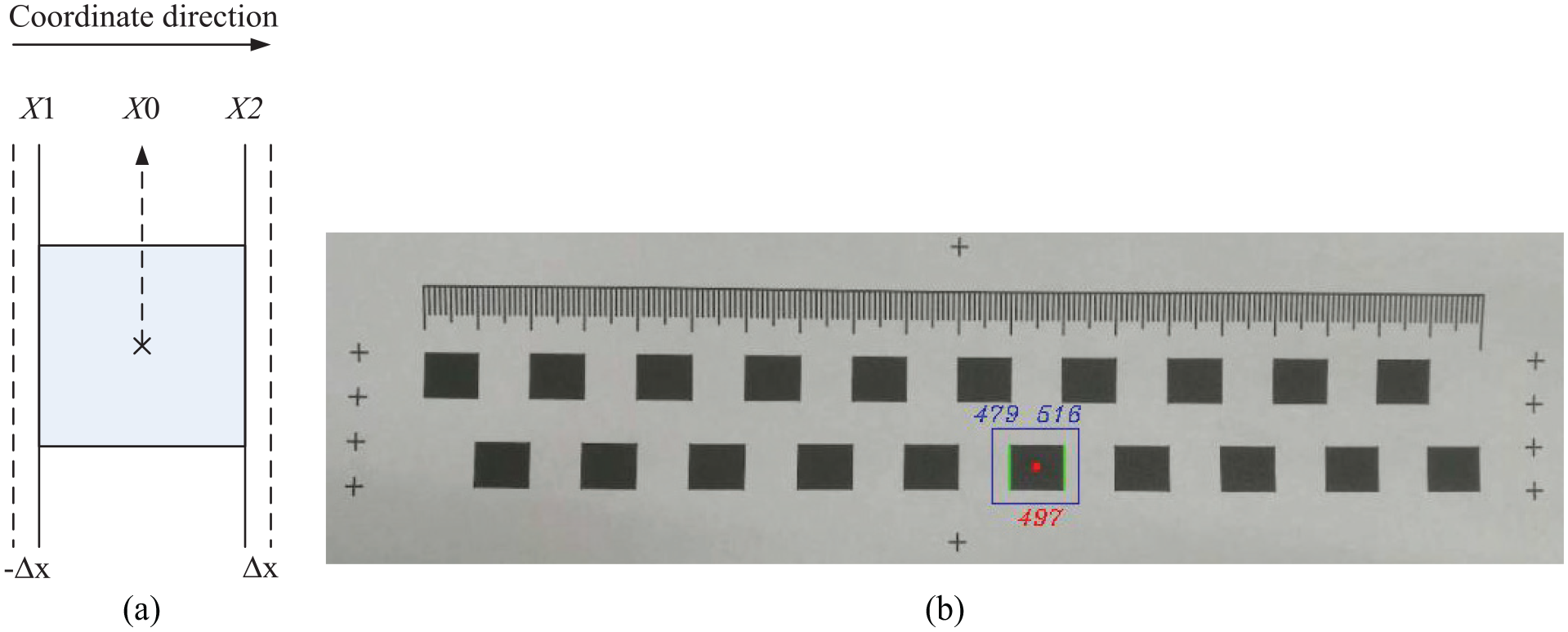
Bilateral linear extraction: (a) Principle diagram. (b) The bilateral threshold segmentation of monitoring target.
Hough transform is used to extract the line after threshold segmentation, which maps the image coordinate plane into a polar coordinate plane; thus, the line extraction of the image plane becomes a common point problem in the polar coordinate, which can effectively extract the bilateral lines of the target “square,” as shown in Figure 6.
System calibration
As can be seen from the target designed in Figure 1(b), it is composed of a series of standard squares with equally spaced distribution, and the square spacing is 10 mm. Therefore, it can be used as calibration equipment, and thus, a self-calibration method for visual measurement can be established. The relationship between pixel position and longitudinal displacement is obtained, which makes it possible to calibrate the instrument in the field.
In the calibration process, the image processing algorithm is used to identify the pixel position of the center of each square, and then, the actual distance between them is obtained by the target. The unitary linear regression equation of the pixel position and the actual position is established by using the least square method, 16 and the relationship is as follows

In which, y is the actual position, x is the pixel position, b is the slope, that denotes the magnification relationship between y and x, and b0 is the intercept of the regression line on the y-axis, that is, its position. Here, the key issue is to determine b and b0, which can be derived from the pixel position of the center of N squares and their actual position (xi, yi)
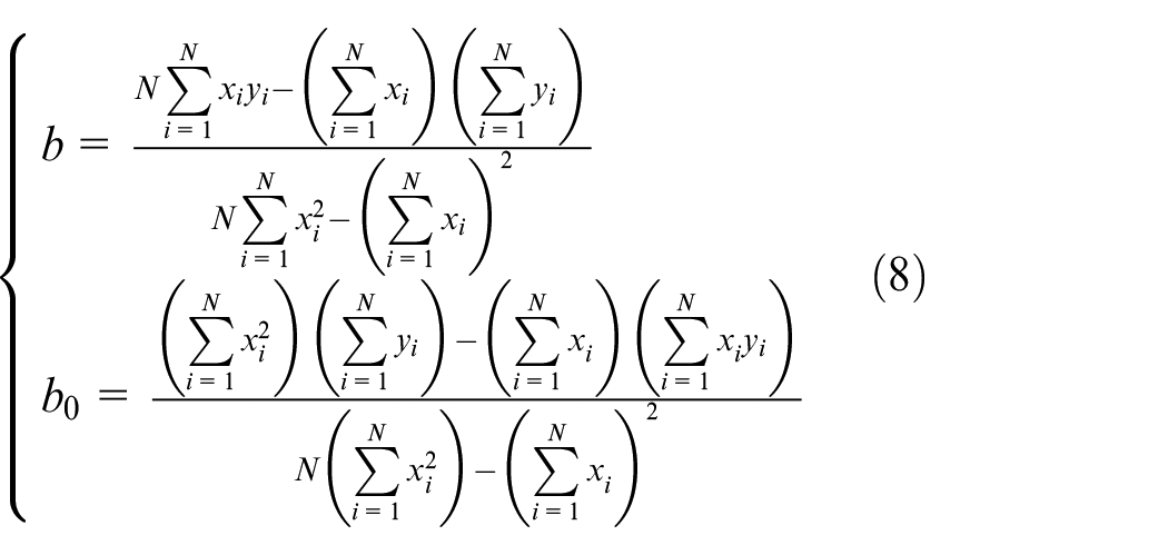
Then, the rail creeping measurement system is calibrated, and the results are shown in Figure 7.
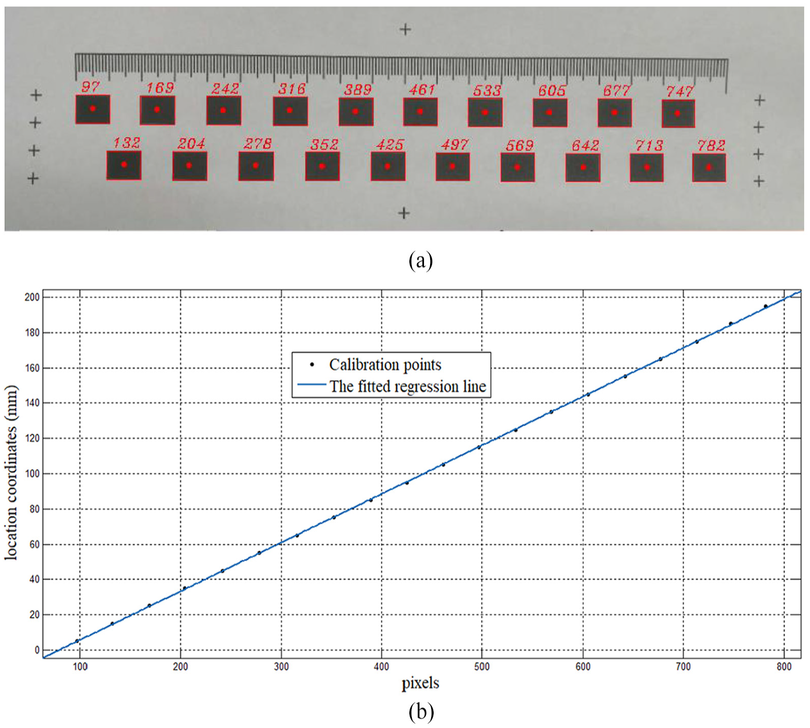
The calibration based on the least square method: (a) The obtained module center pixels for calibration. (b) The fitted line based on the pixel positions and the actual positions.
According to the experimental data in Figure 7, the linear regression equation can be obtained as

From Figure 7(b), it can be seen that a good fitting result is obtained, the root mean square error (RMSE) is 0.4216, the sum of squared errors (SSE) is 3.199 and the coefficient of determination (R-square) is 0.9999.
The experimental testing
The monitoring system has been tested experimentally. The target is installed to a ball-screw device, which can generate the standard displacement, and the monitoring system monitors the target movement to obtain measurement data. The test results are shown in Table 1.
The test results of the monitoring system.
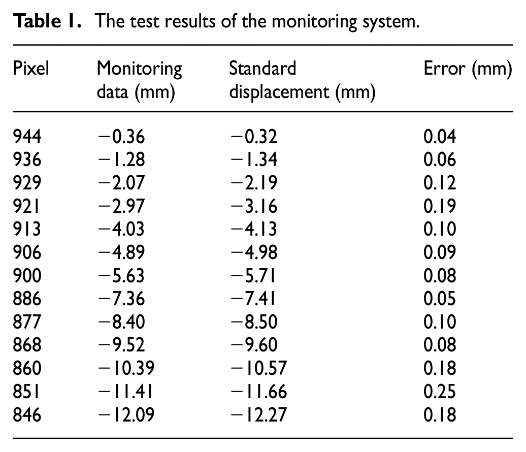
As can be seen from the data in the table, the maximum error of the monitoring system is 0.25 mm. The measurement error of the artificial drawing method is 5 mm and the laser observation method and mark-dot method are 1 mm.6,7 Therefore, this system has higher measurement accuracy and can realize online measurement.
In the actual measurement process, the initial step should set “zero” to the instrument, which also determines the monitoring target “square” at the same time. The center of the target “square” is used as the reference point, and then, its relative movement is monitored. According to formula (9), the relative displacement in the longitudinal direction can be calculated. The software interface of the monitoring system is shown in Figure 8.
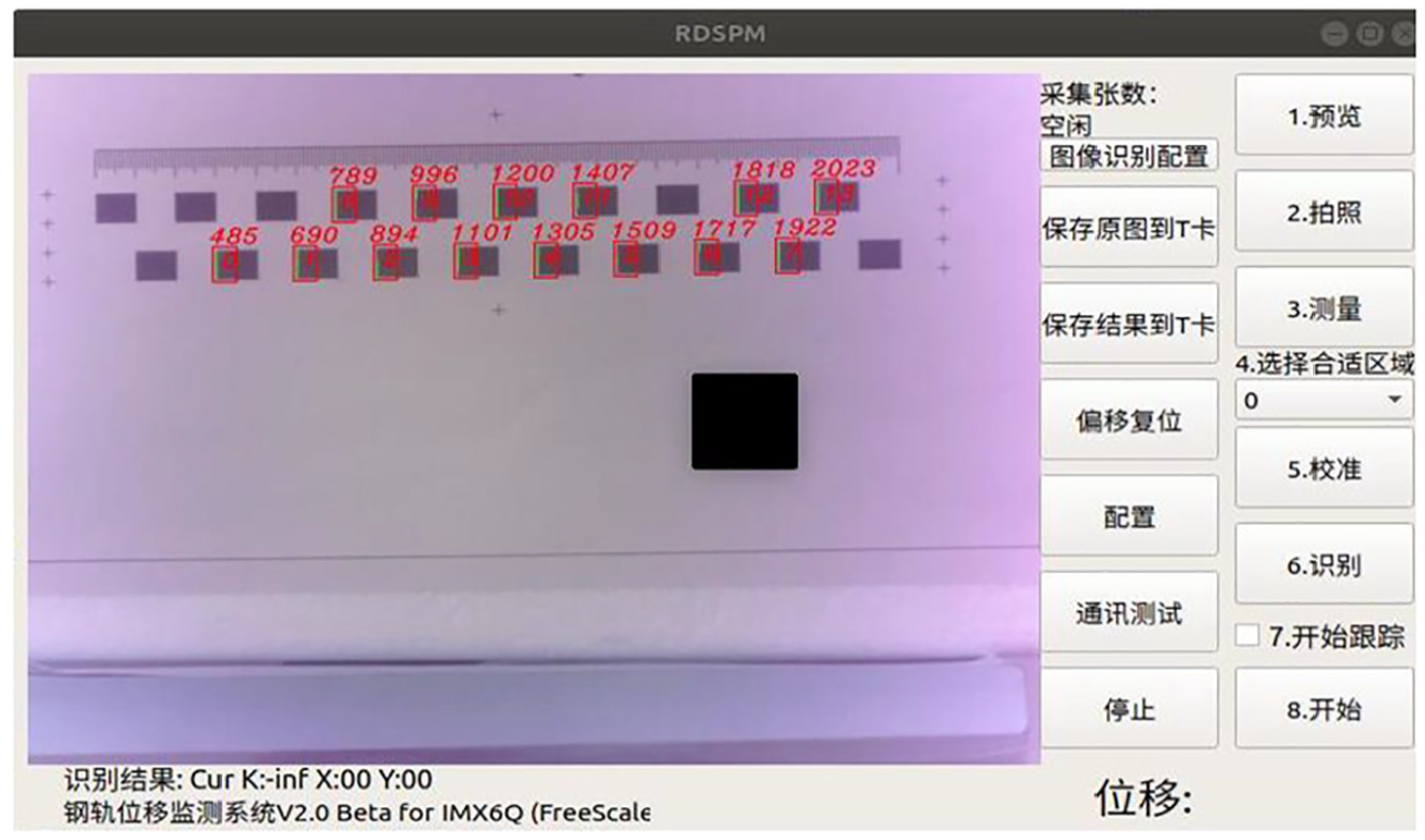
The monitoring software interface.
NB-IOT is a narrow-band Internet of Things with strong coverage, low cost, low power consumption and strong connectivity. It can connect directly to China mobile Internet of Things platform OneNET. In this paper, the actual data of rail creeping displacement are just transmitted to the cloud platform through NB-IOT, which are shown in Figure 9. It can be seen that the displacement fluctuates with time. The system can monitor the rail state in real time, which provides a guarantee for the safe and stable operation of high-speed railway.
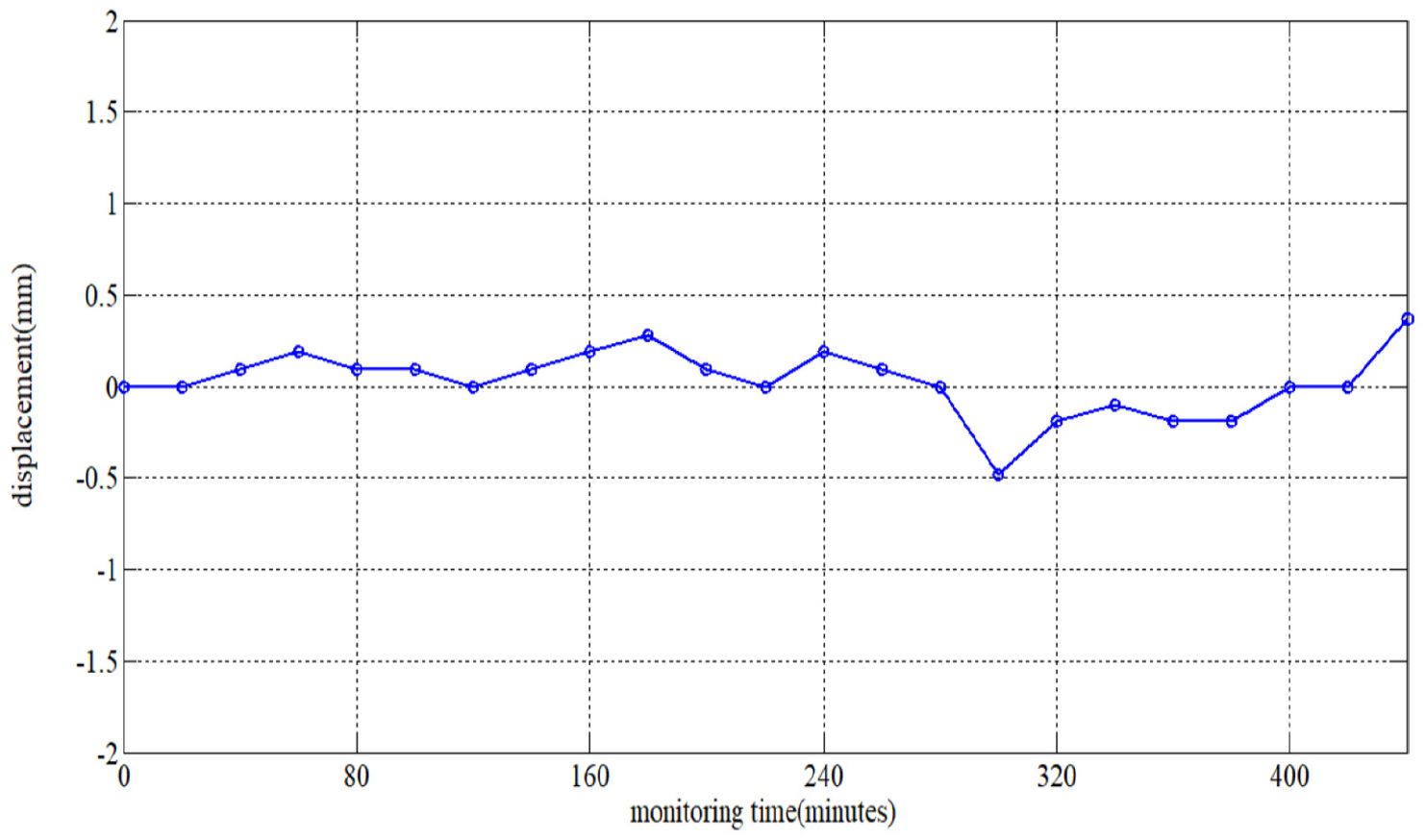
Rail displacement monitoring data.
Conclusion
This paper studies a remote monitoring system based on machine vision aimed at the issue of high-speed railway rail creeping. In the system, the target is sprayed on the rail waist and the device is installed on the observation pile, which will not affect the existing railway facilities. It completes the target recognition, creeping displacement monitoring through image processing technology, and transmits the data to the cloud server through NB-IOT for analysis and processing. Through the control of light source for night vision and the detection of vibration sensor, it overcomes the interference of environmental factors to creeping displacement monitoring. These guarantee the safe and stable operation of the high-speed railway.
Footnotes
Declaration of conflicting interests
The author(s) declared no potential conflicts of interest with respect to the research, authorship and/or publication of this article.
Funding
The author(s) received no financial support for the research, authorship and/or publication of this article.