
Abstract
This article investigates the meshing performance of planetary roller screws applying rollers with circular, elliptical, and parabolic threads. A mathematical model is established for the thread surface, and a method for analytically calculating the meshing points was developed. The meshing point distributions and interference risk area are calculated to analyze the meshing characteristics of the thread shapes considered. The possibility of applying elliptical thread and parabolic thread to the rollers of planetary roller screws in place of the commonly employed circular thread was explored, and elliptical threads were determined to provide better meshing positions, achieve higher transmission speeds, and obtain longer working lifetimes.
Introduction
Planetary roller screws are a type of transmission device that can convert the rotation of a screw into the linear motion of the nut using threaded rollers as mediators. Because of the many advantages of this device, such as high speed, high accuracy, low noise, and long working life, it is widely used in the areas of aerospace, military equipment, numerical control machinery, industrial robots, and medical equipment and is taking the place of hydraulic equipment in many applications.
Considerable research has been conducted regarding the manufacture, parameter matching, kinematic analysis, 1 and stiffness, friction torque, 2 and efficiency calculations of planetary roller screws. 3 However, previous research has been based on the assumption that the screws apply straight threads and the rollers apply circular threads, 4 and this assumption has ignored that the shape of the roller thread may have significant effects on the performance of a planetary roller screw.
The transmission of a planetary roller screw relies on the external meshing of the screw thread and the threads of the roller, and this external meshing makes the position of the mesh point reside outside the plane determined by the screw and roller axes (i.e. the cross section). The meshing position is very important for evaluating the meshing performance of a planetary roller screw 5 and is determined by the lead angle and the shape of the thread. Our team focuses on the meshing properties of planetary roller screw and has a deep base in calculating the meshing position of planetary roller screw.7,8 This article raises the issue of applying thread shapes other than the commonly employed circular thread to a planetary roller screw system for the first time and discusses the influence of the thread shape on the meshing performance. This article also develops a method for calculating the meshing position 6 between screws with rollers of any thread shape, which may be very useful for design and manufacture of roller screw systems.
Structure of a planetary roller screw
In a planetary roller screw, the screw and nut apply multiple straight threads and the rollers employ single-start threads. The thread shape is determined in the plane through the thread axis. As illustrated in Figure 1, the screw and nut threads share an equivalent thread axis, and the rollers are distributed symmetrically in the circumference between the threads of the screw and nut. There are two sets of intermeshing thread structures in the planetary roller screw: one is the external thread meshing between screw thread and roller screw and the other is internal thread meshing between screw thread and nut thread. The rollers are fixed on the nut by an inner ring gear, a retaining plate, and a wire ring. No axial movement occurs between the rollers and nut, such that transmission is achieved by the meshing behavior of the screw thread and roller threads.

The structure of a planetary roller screw: 8 1, nut; 2, roller; 3, screw; 4, inner ring gear; 5, retaining plate; 6, wire ring.
Mathematical modeling of the thread surface
The surface of the thread can be defined by the lead angle

Thread surface coordinate system.
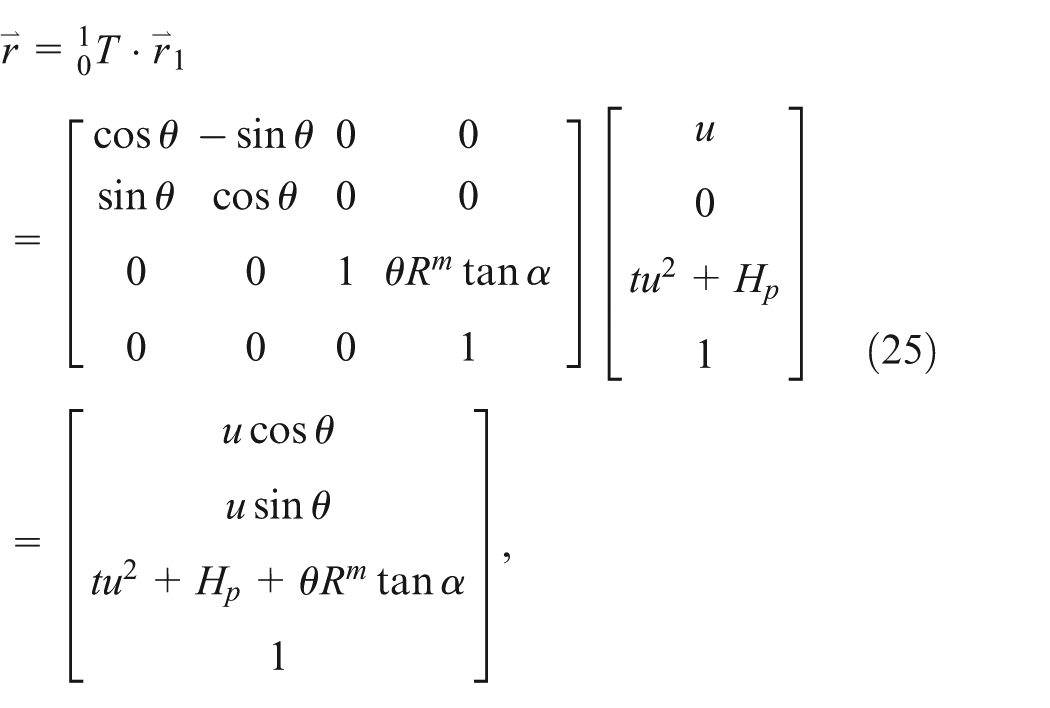
The homogeneous transformation matrix
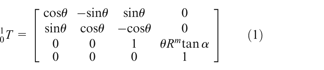
where
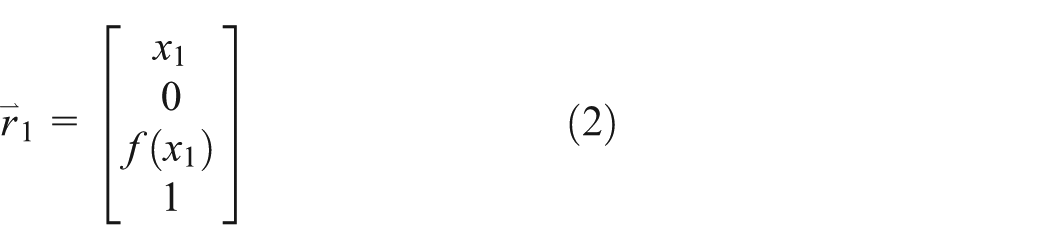
The homogeneous coordinates in S can therefore be expressed as
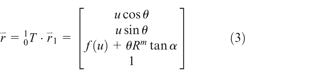
Here, u is the radial distance from P to the thread axis.
Taking u and


As such, a mathematical model for different thread shapes can be constructed by employing the appropriate thread shape function
Mathematical model of straight thread
Straight thread is widely used as the screw and nut thread in planetary roller screws because it is easily machined and achieves high working accuracy. The shape of the thread is measured in the

Sectional view of straight thread.
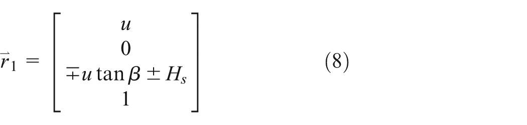
The shape function in the

Here, as in the other equations presented unless specified otherwise, the upper “+” or “−” symbol indicates the upper surface of the thread and the lower “+” or “−” symbol indicates the lower surface of the thread with respect to Figure 3. The homogeneous coordinate of the thread shape in
and the homogeneous coordinates can be transformed to
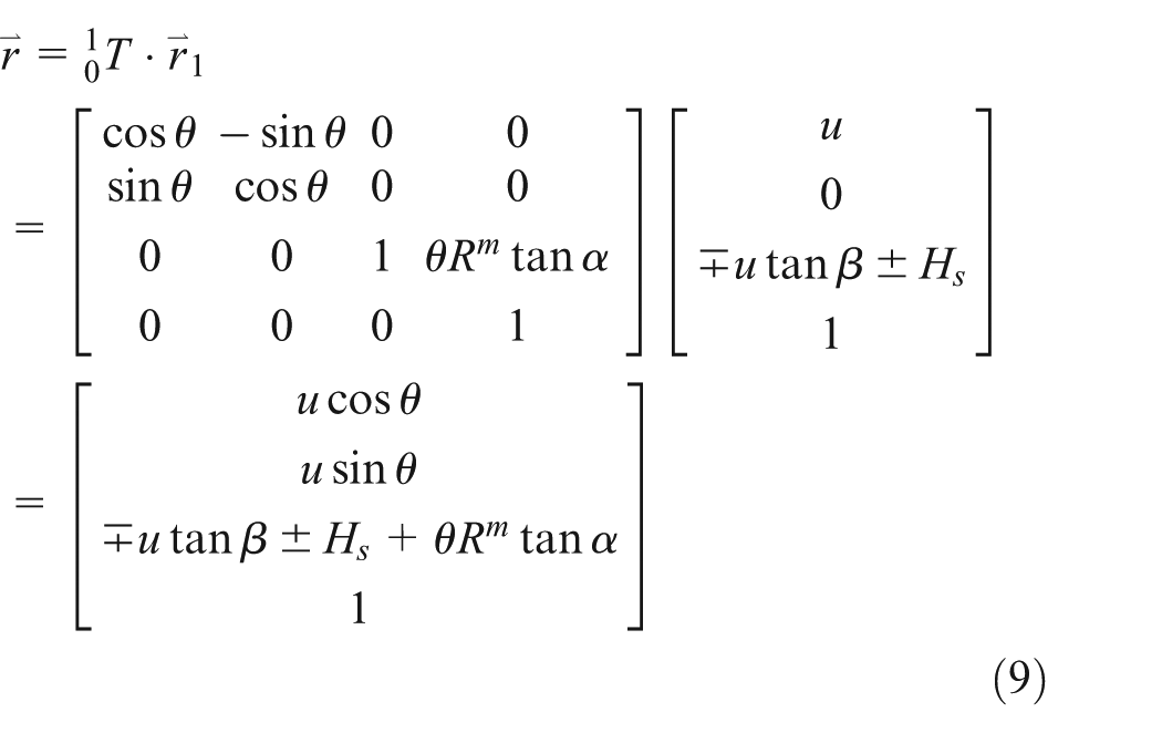
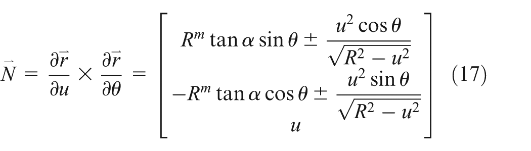
Differentiating equation (9) with respect to u and

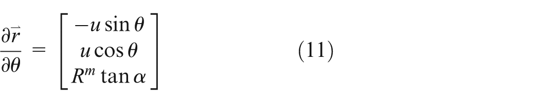
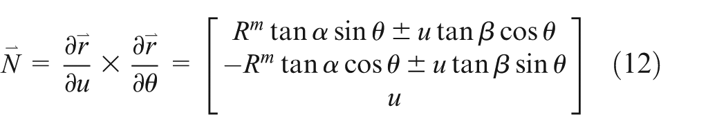
The normal vector at a point on a straight thread surface can therefore be calculated as follows
Mathematical model of circular thread
Circular thread is typically used as the roller thread for readily available planetary roller screw products. A sectional view of circular thread is shown in Figure 4 in terms of the radius of the thread contour circle R from its center point Oc of height Hc along the z1-axis to the center of thread O1, and an angle γ with respect to the z1-axis can be used to represent different positions on the thread contour.
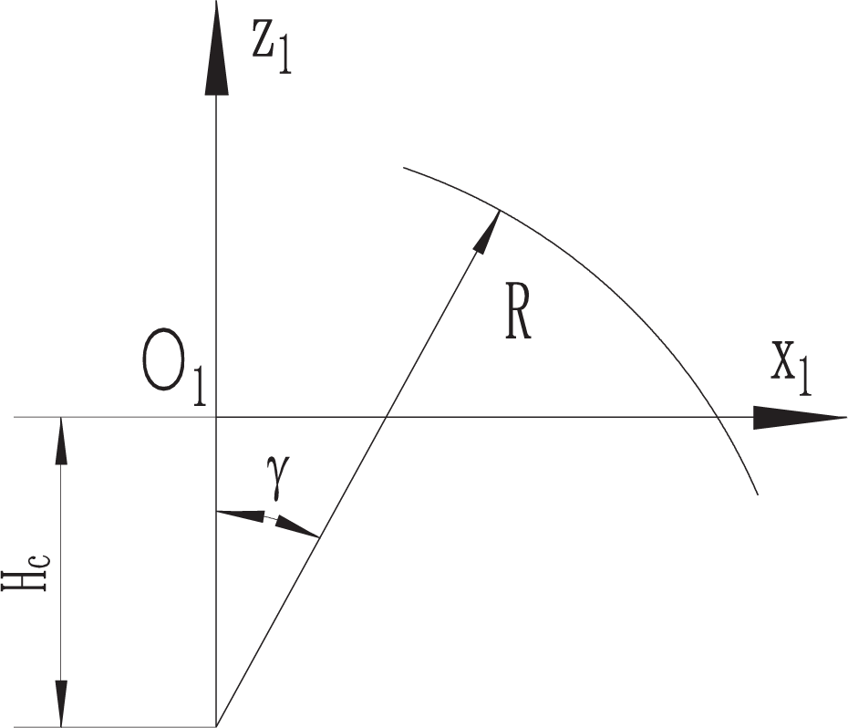
Sectional view of circular thread.
In the

The homogeneous coordinates representing the circular thread contour in

and the homogeneous coordinates can be transformed to

Here, because

The normal vector of any point on the circular thread surface
Mathematical model of elliptical thread
Elliptical thread can also be employed for roller thread, which is also measured in the

Sectional view of elliptical thread.
In the
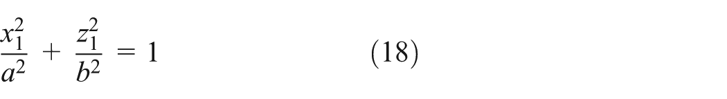
The homogeneous coordinates representing the elliptical thread contour in

and the homogeneous coordinates can be transformed to

Here, because

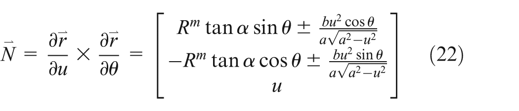
The normal vector of any point on the elliptical thread surface
Mathematical model of parabolic thread
Figure 6 provides a sectional view of a parabolic thread applied to a roller with a contour height Hp measured in the

Sectional view of parabolic thread.
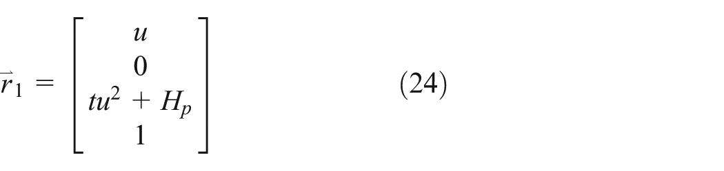
In the

where t is the parabola shape parameter. The homogeneous coordinates representing the parabolic thread contour in
and the homogeneous coordinates can be transformed to
The normal vector of any point on the parabolic thread surface

Calculation of the meshing position
The screw thread and roller threads of a planetary roller screw externally mesh at their pitch diameters, and the thread axes are parallel. The meshing condition is that the position vector of the meshing point on the screw thread surface equals that on the roller thread surface, and their normal vectors lie in the same direction. Meshing equations can therefore be constructed to calculate the meshing point based on the meshing condition as follows
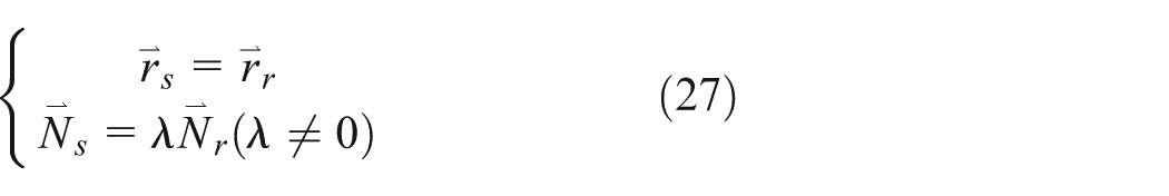
Here, and for other variables used henceforth unless otherwise indicated, the subscripts s and r represent the parameters of the screw and roller, respectively.
A common method for calculating the meshing position is building the meshing equations with a given distance between the screw and roller axes and calculating the meshing radii and meshing angles as shown in Figure 7. The equations built applying this method are very complex and are often solved using numerical methods. While a numerical method can be used to establish accurate mesh point positions for a planetary roller screw with given parameters, numerical calculations have serious limitations when working with the parametric equations appearing in the design and development process.

Meshing point measured in the plane perpendicular to the screw and roller axes.
In this study, several parameters are formalized to simplify the meshing equations and to make it possible to establish analytical solutions of the meshing positions as follows. The meshing point occurs on the xs-axis (Figure 7), which means that
The normal vectors of the meshing points at the thread surfaces of the screw and roller can be expressed as follows

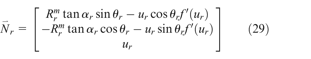
By substituting equations (28) and (29) into

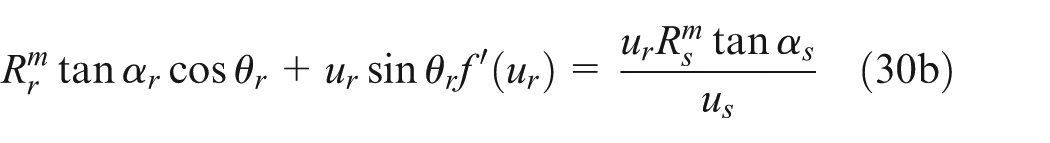

Summing the squares of the two equations in equation (30) results in an equation in which

We can solve for

We can solve

We can then solve for
According to equation (31), we can achieve the result of

Because the meshing radius and the lead radius of the screw and roller are almost same, and the screw and the roller often use the same tooth angle, in the case of
The relative position between the screw and roller can now be calculated based on

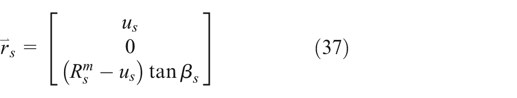
and the position of the meshing point in the screw coordinate system

The coordinates of meshing points for the proposed analytical calculation.
The relative position between the screw and roller is then equal to the relative position between

The distance between the screw and roller axes can be calculated as
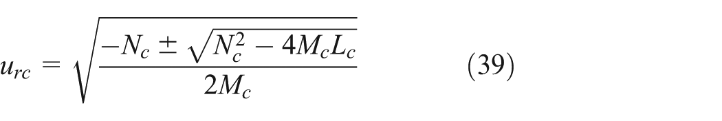
The corresponding meshing radius can then be established by applying the above method using a circular, elliptical, or parabolic thread shape function. The equation for calculating the meshing radius of a circular thread roller is as follows
The equation for calculating the meshing radius of an elliptical thread roller is as follows


The equation for calculating the meshing radius of a parabolic thread roller is as follows

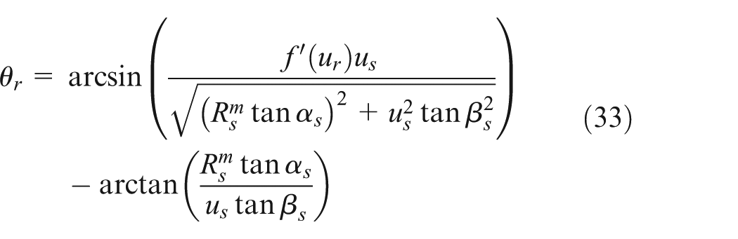
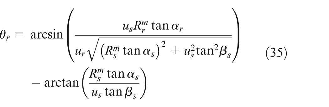
The meshing angle can be obtained by substituting the calculated meshing radius into equation (35). The positions of the screw thread and roller thread can be calculated based on the calculated meshing radius and meshing angle.
Simulation of thread meshing
This section will employ specific data to calculate and analyze the meshing positions of a planetary roller screw applying rollers with different thread shapes. The data used in the simulations are listed in Table 1. The data in Table 1 are input into the equations derived in section “Calculation of the meshing position,” and MATLAB is employed to simulate the meshing between screw and roller.
Parameters of planetary roller screws with different thread shapes.

Figure 9 shows the changing positions of meshing points on roller thread surfaces with various shapes following a change of

Meshing points indicated by the colored lines under different
In the actual meshing process, the value of
Positions of meshing points under varying parameters
When the pitch diameters of the screw and rollers are fixed, the most important parameters are the pitch and number of threads. Rollers apply single-start thread, and screws apply multiple threads.
The meshing points of the three different thread shapes were calculated using different pitch values from 0 to 10 mm in intervals of 0.5 mm which are applied to both screw threads and roller threads with all other parameters being those listed in Table 1. The resulting variation in the meshing points is shown by the colored lines in Figure 10.
Meshing points indicated by the colored lines under different pitch values from 0 to 10 mm in 0.5 mm intervals (20 data points).
As shown in Figure 10, when the pitch changes from 0 to 10 mm, the varying meshing points on the roller thread surfaces represent curves away from the thread axis. When the value of the pitch is 0, the threads become parallel ring structures, and the meshing points are close to the pitch diameter. With increasing pitch, the meshing radii on the roller thread surfaces increase, and the meshing points move toward the crest of the thread. The crest of the thread has a smaller thread tooth thickness and poorer bearing capacity. As a result, meshing at this location may cause larger deformations or even failure. The meshing points on the circular thread move toward the crest at a moderate rate with increasing pitch, whereas the meshing points on the elliptical thread move at a much slower rate and maintain a position close to the pitch diameter. The meshing points on the parabolic thread rapidly move away from the axis and beyond the thread surface. As such, elliptical thread rollers are observed to have better meshing locations that allow the application of a larger pitch, which supports a larger transmission speed. Therefore, a comparison with the widely applied circular thread rollers indicates that planetary roller screws applying elliptical thread rollers would provide better performance and achieve higher transmission speeds.
As shown in Figure 11, with the number of screw threads increasing from 1 to 10, the meshing points move toward the crest of the thread. Like the results obtained when varying the pitch, the elliptical thread exhibits the best meshing locations and the parabolic thread the worst. Relative to the results obtained with increasing pitch, a larger number of screw threads impacts the meshing points to a lesser extent.

Meshing points indicated by the colored lines under different number of screw threads from 1 to 10 (10 points).
It has been shown that applying elliptical thread rollers can help improve the meshing performance of planetary roller screws and is especially suitable for applications employing large pitch and a greater number of screw threads to achieve high speed transmission. Elliptical thread rollers demonstrate a stable meshing radius and a meshing point close to the pitch diameter, which is advantageous for improving the bearing capacity of planetary roller screws.
Analysis of interference risk
In the area around a meshing point, the distance between the two meshing surfaces is very small. As such, interference may occur in this area in the presence of a large deformation or wear. This area is therefore denoted as the interference risk area. In addition to the risk of interference, the small space between the meshing surfaces in this area is not conductive to the dissipation of heat, and, therefore, a smaller interference risk area is beneficial for both lowering the risk of interference and increasing the working life.
This study employs an interference function

Here,

At the meshing point, the value of the interference function is 0, that is,
The data in Table 1 were employed to calculate the meshing location, which were substituted into equation (42) with
The interference risk area of the thread shapes considered.
As shown in Figure 12, the elliptical thread exhibits the smallest interference risk area and the parabolic thread the largest. This demonstrates that a planetary roller screw applying elliptical thread would have lower risk of interference and enhanced heat dissipation, thereby prolonging its working life.
Conclusion
A mathematical model of screw/roller thread was constructed, and a method for analytically calculating the meshing points was developed. The proposed method was demonstrated to be applicable to planetary roller screws applying any type of roller thread. Based on the meshing calculations, the study explored the possibility of applying elliptical thread and parabolic thread to the rollers of planetary roller screws in place of the commonly employed circular thread. The meshing performance of planetary roller screws was also analyzed from the viewpoints of the meshing points distribution and interference risk, and the application of elliptical thread rollers was found to provide the best performance. Planetary roller screws applying elliptical thread would provide better meshing positions, achieve higher transmission speeds, and obtain longer working lifetimes.
Footnotes
Academic Editor: Aditya Sharma
Declaration of conflicting interests
The author(s) declared no potential conflicts of interest with respect to the research, authorship, and/or publication of this article.
Funding
The author(s) disclosed receipt of the following financial support for the research, authorship, and/or publication of this article: This work was supported by the National Natural Science Foundation of China (grant no. 51305010). This work was also supported by the project YCSJ-03-2016-07 supported by the Graduate Innovation Practices Foundation of Beihang University.