
Abstract
The required thickness of the carbon steel overpack for high-level radioactive waste geological disposal in Japan was re-evaluated based on the latest scientific and engineering knowledge. The re-evaluation of the required thickness was carried out for the concept of vertical emplacement in a hard rock system (which requires the greatest overpack thickness). The re-evaluation was carried out to meet design requirements for corrosion resistance, structural integrity and the prevention/reduction of detrimental radiation effects on corrosion resistance. The re-evaluated minimum thicknesses to assure a lifetime greater than 1000 years were 122 mm for the flat end plate and 91 mm for the cylindrical body. Therefore, the applicability of the reference thickness (190 mm) for the overpack was reconfirmed.
This paper is part of a supplement on the 6th International Workshop on Long-Term Prediction of Corrosion Damage in Nuclear Waste Systems.
Keywords
Introduction
Geological disposal in Japan is based on the concept of a multi-barrier system that constitutes both engineered and natural barriers. Host rock types are broadly classified into two groups: hard rock systems and soft rock systems [1]. For the disposal of high-level radioactive waste (HLW), the vitrified waste is contained in a metal overpack emplaced with bentonite buffer and together constitutes the engineered barriers. Two directions of emplacement of the overpacks have been considered to date, either vertical or horizontal disposal. Figure 1 shows the basic concept of the geological disposal system for disposal of HLW in Japan and its expected safety functions [2]. The use of an overpack aims to prevent contact of groundwater with the vitrified waste during the high heat generation period of the first 1000 years after emplacement. Thus, ensuring a significant radioactivity decay produced by the short-lived radionuclides and also to provide preferable conditions for safety assessment such as, moderate temperatures and full-saturation of the bentonite buffer.
Basic concept of the geological disposal system for HLW in Japan and its expected safety functions.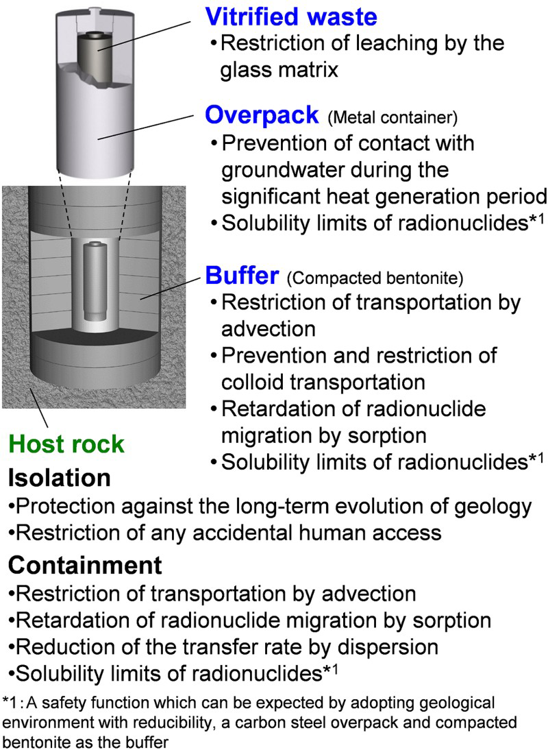
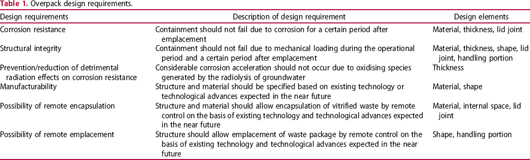
Overpack design requirements.
Design requirements and design procedure for verification of overpack thickness
Each design element for the overpack has to meet the design requirements listed in Table 1. The design requirements are determined from the viewpoints of post-closure long-term containment, pre-closure containment and manufactural/engineering possibility. The design requirements for the thickness of the overpack are corrosion resistance, structural integrity and the prevention/reduction of detrimental radiation effects on corrosion resistance.
First, the appropriate ‘corrosion allowance’, ‘pressure resistance thickness’ and ‘radiation shielding thickness’ to meet design requirements were evaluated, after which, the overall thickness of the overpack was determined based on these three thicknesses.
Corrosion allowance
Corrosion scenario for the carbon steel overpack
The environment in which corrosion of the overpack will take place will be dependent on the repository site which has not yet been selected in Japan. In addition, the chemistry of groundwater in Japan varies widely from fresh to saline water, as a consequence of geographical and climatic reasons [3] and furthermore, the environment in which corrosion will take place will evolve with time. The temperature at the surface of the overpack is not expected to exceed 100°C at the peak of the thermal transient, after which it decreases with the radioactivity decay until reaching the ambient temperature of the host rock. The water content of the compacted bentonite surrounding the overpack is assumed to be low initially, but increases with time and will eventually reach saturation as groundwater fills the repository. When this happens, the environment around the overpack will become increasingly anaerobic as the initial trapped oxygen will be consumed by various processes, including corrosion.
Therefore, the corrosion allowance for the overpack was evaluated for both aerobic corrosion in the early period after emplacement and anaerobic corrosion that takes place over the longer term. In addition, other corrosion processes such as the possibility of stress corrosion cracking (SCC), hydrogen-induced cracking (HIC) and microbiologically influenced corrosion (MIC) were also evaluated because the overpack could be damaged early by these corrosion processes.
Aerobic corrosion
In terms of aerobic corrosion, the mean corrosion depth was assessed assuming that all the oxygen in the compacted bentonite and backfill material is consumed by corrosion of the overpack. The maximum corrosion depth was estimated by the evaluation of pitting.
Mean corrosion depth
The amount of oxygen per overpack was evaluated to be 590 mol [1], assuming that all the oxygen in the compacted bentonite and backfill material is consumed by corrosion of all overpacks. This amount of oxygen will corrode 1180 mol of Fe in accordance with the following reaction:

Maximum corrosion depth
The plot in Figure 2 shows the variation in pitting factor (the ratio of the maximum corrosion depth to the mean corrosion depth) as a function of the mean corrosion depth. Pitting factors for general corrosion of rolled steel (JIS G 3106 SM400B) [4,5] and localised corrosion due to the breakdown of the passive film of rolled steel (JIS G 3106 SM400B) and forged steel (JIS G 3202 SFVC1) [5] (this type of corrosion is considered to be unlikely because carbon steel is difficult to be passivated in compacted bentonite within a HLW repository environment [1,6], however, the investigation is carried out considering uncertainties in the nature of the disposal environment) were obtained by immersion tests under generic solution conditions and actual groundwater conditions at Horonobe Underground Research Laboratory as an example of typical marine groundwater. Pitting factors for localised corrosion of rolled steel (JIS G 3106 SM400B) in unsaturated bentonite [7] were also obtained. The plot also shows values for a range of different environmental samples in situ, e.g. various soil types [8], tropical water [9] and the bottom face of old oil storage tanks which had been resting on soil [10]. It was found for all synthetic and natural samples that the degree of roughness diminishes with increasing mean corrosion depth.
Relationship between pitting factor and mean corrosion depth for carbon steel measured in various synthetic solutions and a range of different environmental samples in situ (after Taniguchi et al. [11]).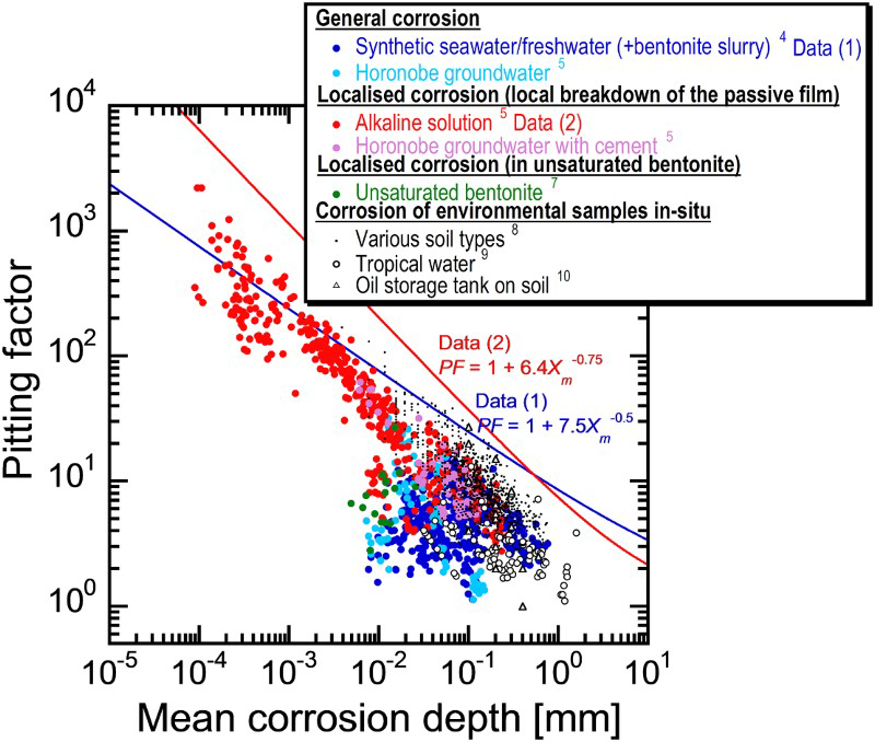
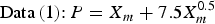
In order to estimate the maximum corrosion depth for an overpack, Taniguchi et al. [5] applied the extreme value statistical analysis technique to the pitting factor data of Data (1) and Data (2) in Figure 2. The upper of the extreme value statistical analysis result is expressed by the following equation (see Taniguchi et al. [5] for details due to limitations of space):

Therefore, the maximum corrosion depth of an overpack was estimated with a larger PF than either of Equations (4) or (5). As a result, the maximum corrosion depth for the concept of vertical emplacement in a hard rock system was estimated to be 11 mm using Equation (4) (from a mean corrosion depth 1.5 mm). This maximum corrosion depth was set as the corrosion allowance for aerobic corrosion.
Anaerobic corrosion
In terms of anaerobic corrosion, the mean corrosion depth for 1000 years was evaluated from corrosion tests performed under anaerobic conditions. The maximum corrosion depth was estimated by the evaluation of pitting.
Mean corrosion depth
The mean corrosion depth for 1000 years was evaluated on the basis of immersion tests [12] of rolled steel (JIS G 3106 SM400B) embedded in compacted bentonite under anaerobic conditions for up to 10 years. The test solutions were synthetic sea water at 80 and 50°C, synthetic freshwater at 80°C and a high-carbonate solution at 80°C. Figure 3 shows changes in mean corrosion rate with time over the 10-year experimental period. It was found that the mean corrosion rates under all conditions decreased with time. The highest mean corrosion rate measured for the 10-year period was about 2 μm/y. Corrosion products on carbon steel identified by XRD analysis were mostly FeCO3 or Fe2(OH)2CO3, although Fe3O4 was detected on carbon steel tested in the synthetic freshwater at 80°C for 10 years.
Changes in mean corrosion rates of carbon steel embedded in compacted bentonite immersed in a range of solutions under anaerobic conditions (after Taniguchi et al. [12]).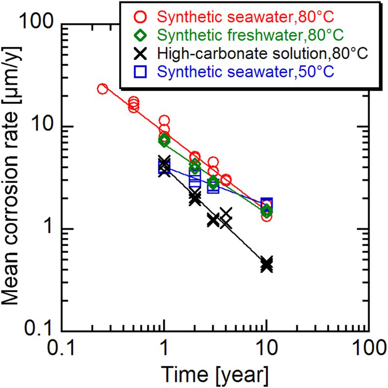
From Figure 3 it can be seen that there is little visible difference between the corrosion behaviour in synthetic sea water and that in freshwater. Therefore, from Figure 3 it can be deduced that the corrosion behaviour of carbon steel in saline and fresh groundwater will not be so different. The degree of decrease in mean corrosion rate at 80°C is greater than that at 50°C in synthetic sea water. In addition, the mean corrosion rate in the high-carbonate solution is less than that observed in the other solutions studied. The reason for these behaviours is considered to be because the smaller the solubility of FeCO3 (the solubility is smaller as the temperature is higher) and the higher the carbonate concentration, the easier the precipitation of FeCO3 and the greater the corrosion inhibiting effect [12].
Although the degree of corrosion inhibition caused by the precipitated corrosion film is different and depends on temperature and carbonate concentration, Figure 3 shows that the mean corrosion rates under all conditions continue to decrease with time. Thus, it is likely that the mean corrosion rate will not become greater than 2 μm/y after a period of 10 years as long as the precipitated corrosion film is stable.
The mean corrosion depth under anaerobic conditions for 1000 years was estimated to be 2 mm, assuming a constant corrosion rate of 2 μm/y.
Maximum corrosion depth
The pitting factor for corrosion of rolled steel (JIS G 3106 SM400B) embedded in compacted bentonite (dry density: 1.8 Mg m−3) immersed in synthetic sea water under anaerobic conditions was obtained by constant-current acceleration tests and immersion tests [13]. In order to estimate the maximum corrosion depth for the overpack, the extreme value statistical analysis technique was applied to this pitting factor data.
The estimated maximum corrosion depth of an overpack by the extreme value statistical analysis technique is given by

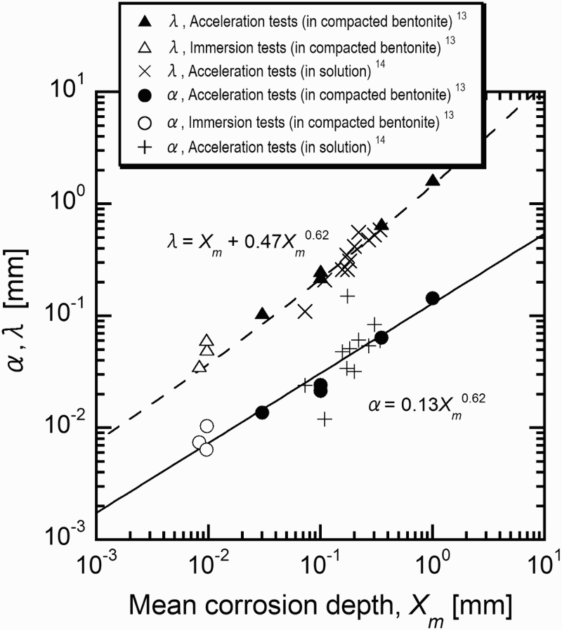
Figure 4 shows relationships between mean corrosion depth, α and λ which are derived by the extreme value statistical analysis of pitting factor data obtained by constant-current acceleration tests and immersion tests [13]. The α and λ which are obtained by constant-current acceleration tests without compacted bentonite carried out by Akashi et al. [14] are also plotted in Figure 4. By describing α and λ as a function of the mean corrosion depth (Xm) and substituting in Equation (6), P can be expressed as a function of the mean corrosion depth. α was described by a form of α = k1Xm n, where k1 and n are constants and the following equation for α was obtained:
Relationships between mean corrosion depth, α and λ which are derived by the extreme value statistical analysis of pitting factor data obtained by constant-current acceleration tests and immersion tests (after Taniguchi et al. [13]).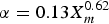
 with constants of k2 and n′ were applied. In order to simplify the equation, n′ was set to be 0.62 and the following equation for λ was obtained:
Stress corrosion cracking and hydrogen-induced cracking
In the assessment of corrosion depth above, stress corrosion cracking (SCC) and hydrogen-induced cracking (HIC) were not considered. However, it is necessary to justify the exclusion of these corrosion processes.
SCC requires the presence of both a suitable environment (such as high-carbonate concentration for carbon steel) and a suitable tensile stress. These requirements are basically the same for HIC. SCC and HIC were assessed as not likely to occur because experimental data which are currently available, indicate that carbon steel is not prone to these processes in a HLW repository environment [1]. Considering uncertainties in the nature of the disposal environment, however, the assessment of the possibility of SCC or HIC from the viewpoint of the suitable tensile stress was also carried out.
Tensile residual stresses in the weld region could be a factor that may cause SCC and/or HIC to occur. In order to improve residual stresses in the welded region, the effects of post weld heat treatment (PWHT) and external induced heating stress improvement (EIHSI) were evaluated by finite element analysis [15]. According to the evaluation result [15], the tensile residual stress for the corrosion allowance could be decreased to almost zero or changed to compressive stress by PWHT or EIHSI without heating damage to the vitrified waste. Therefore, overpack failures by SCC and HIC are considered unlikely, but it will be necessary for these stress improvement methods to be demonstrated in any future development work.
Microbiologically influenced corrosion
In common with many structural alloys, carbon steel is susceptible to microbiologically influenced corrosion (MIC) in the presence of active microbes. However, it is generally assumed that the repository environment is not conducive to microbial activity [16], primarily because of the low water activity in compacted bentonite. Consequently, MIC will only result if corrosive metabolic byproducts of microbiological activity in host rocks reach the overpack surface. Sulphate reducing bacteria (SRB) are known to be one of the most common microbes which affect the corrosion of metals. The effects of sulphide produced by SRB on the corrosion of overpack materials were studied by Taniguchi et al. [17]; they made the conservative assumption that the activity of SRB in host rock would be high. Taniguchi et al. [17] carried out immersion tests of carbon steel which was embedded in compacted bentonite immersed in synthetic sea water that had been purged with 0.1 MPa H2S gas. As a result, it was reported that there were no obvious effects of sulphide on the corrosion of carbon steel while on the other hand, the corrosion of copper was accelerated. Therefore, acceleration of the corrosion rate of the carbon steel overpack by microbes seems to be unlikely. Nonetheless, in situ studies at the selected site should be performed to determine if these assumptions are still valid.
Pressure resistance thickness
Once the buffer has saturated with groundwater, hydrostatic pressure and swelling pressure will be applied to the surface of the overpack. The buffer is consolidated due to rock creep deformation and corrosion expansion of the overpack, so the reaction force also acts on the overpack (consolidation stress). Considering these loads, the total value of external pressure was evaluated to be 11 MPa in a hard rock system [1].
Assuming that the external pressure is isotropic, the pressure resistance calculation for the overpack was performed based on the provisions for MC-class containers documented in ‘Codes for Nuclear Power Generation Facilities - Rules on Design and Construction for Nuclear Power Plants’ [18]. When the steel grade is SF340A (JIS G 3201), the resulting required thicknesses of the flat end plate and the cylindrical body were calculated to be 105 and 46 mm, respectively.
Radiation shielding thickness
If the thickness of the overpack is not sufficient, radiation may cause radiolysis and formation of oxidising chemical species that may adversely affect overpack corrosion. Therefore, the shielding thickness was set based on corrosion tests performed under irradiation.
Immersion tests of carbon steel under γ-ray irradiation were carried out by JAEA [19] and Marsh et al. [20] and Shoesmith and King [21] reviewed the influence of a lower limit of dose rate on the corrosion of carbon steel. According to these results, the corrosion rate accelerates in a solution that has a dose rate in excess of 3 Gy/h, but conversely, no acceleration occurred in saturated compacted bentonite. The absence of an acceleration effect in bentonite was considered to be due to buffering by reducing substances such as pyrite [19]. However, the time period over which such a reducing reaction can be assured is unknown. Therefore, the radiation shielding thickness was determined such that an acceleration in corrosion rate will not occur even in the absence of bentonite (i.e. less than 3 Gy/h). Based on shielding analysis the required thickness to minimise corrosion effects from radiolysis was determined to be 80 mm.
It should be noted that it may be possible to reduce the radiation shielding thickness depending on the future progress of research and development.
Setting of thickness
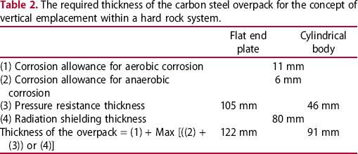
The required thickness of the carbon steel overpack for the concept of vertical emplacement within a hard rock system.
The corrosion allowance for aerobic corrosion (11 mm) should be added to the thickness of the overpack regardless of other required thicknesses because it was evaluated by mass balance and exact time when aerobic corrosion will terminate is unknown (i.e. it should be conservatively considered to corrode instantly after emplacement).
The remaining overpack thickness should be larger than the required pressure resistance thickness and the required radiation shielding thickness over 1000 years (Figure 5). The required radiation thickness will be reduced drastically over time due to attenuation of radioactivity of the vitrified waste. Considering the corrosion allowance for anaerobic corrosion (6 mm), the overpack thickness without the corrosion allowance for aerobic corrosion, should be 111 mm for the flat end plate and 80 mm for the cylindrical body (Figure 5).
Changes in the remaining overpack thickness, the required pressure resistance thickness and the required radiation shielding thickness.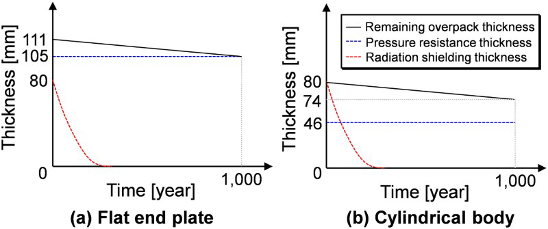
Consequently, the required overall thickness of the overpack can be formulated as below.

In consideration of structural integrity mentioned above, the thickness necessary to withstand the pressure applied uniformly in all directions to the overpack was calculated using the formula specified in JSME [18]. In practice, it is conceivable that loads which differ according to direction (‘asymmetric pressure’) may be applied to the overpack because of asymmetric swelling of the buffer and non-uniform corrosion expansion of the overpack itself. However, it was evaluated that the plasticised area of the overpack with the thickness shown in Table 2 is not connected from the inside to the outside of the overpack, even under extreme asymmetric pressure conditions [1]. Therefore, under the current assumptions, it can be assumed that an overpack with the thickness shown in Table 2 will have a sufficient margin to withstand asymmetric pressure events.
Therefore, based on the latest scientific and engineering knowledge, it was found that the thickness of the carbon steel overpack could be set to 122 mm for the flat end plate and 91 mm for the cylindrical body.
Conclusions
The required thickness of the carbon steel overpack for the concept of vertical emplacement in a hard rock system was re-evaluated based on the latest scientific and engineering knowledge. The re-evaluation was carried out to meet design requirements for corrosion resistance, structural integrity and the reduction/prevention of detrimental radiation effects on the corrosion resistance, so that the re-evaluated required thicknesses were 122 mm for the flat end plate and 91 mm for the cylindrical body. Therefore, the applicability of reference specifications of thickness (190 mm) to the geological disposal system in Japan was reconfirmed.
Footnotes
Acknowledgements
The authors would like to extend their appreciation to Dr H. Inoue of Osaka Prefecture University, Dr N. Taniguchi of JAEA, Dr M. Kawakubo and Dr M. Kobayashi of RWMC and Dr S. Hardie of INTERA for their helpful suggestions in connection with this work.
Disclosure statement
No potential conflict of interest was reported by the authors.