
Abstract
Accurate alignment of anatomical and mechanical joint axes is one of the major biomechanical principles pertaining to articulated orthoses, yet knowledge of the potential effects of axis misalignment is limited. The purpose of this project was to model the effects of systematic linear (proximal-distal and anterior-posterior) misalignments of single axis mechanical ankle joints in an ankle-foot orthosis (AFO) in order to determine the degree and direction of calf band travel that would occur over a functional range of motion. Sagittal plane misalignments of the ankle joint centres of an AFO were simulated using a simple two-dimensional model for both a range of ankle angles and a typical able-bodied ankle kinematic curve for self-selected normal walking speed. The model assumed that no movement occurred between the foot and the foot-plate of the AFO. The model predicted that for anterior (positive horizontal) misalignments, dorsiflexion movements would cause the calf band to travel proximally (i.e., up the leg) and plantar flexion movements would cause the calf band to travel distally (i.e., down the leg). The opposite was predicted for posterior (negative horizontal) misalignments. Proximal (positive vertical) misalignments would cause only distal movements of the calf band while distal (negative vertical) misalignments would cause only proximal movements of the calf band. Anterior-posterior misalignments were found to have a much larger effect on the amount of calf band travel than proximal-distal misalignments.
Introduction
Accurate alignment of anatomical and mechanical joint axes is one of the major biomechanical principles pertaining to articulated orthoses (Lamoreux 1969; Lehneis 1974; Mann 1985; Bowker et al. 1993), yet knowledge of the potential effects of axis misalignment is limited. Accurate joint alignment is a challenge since the location and orientation of joint axes, such as the talocrural (ankle) joint, have long been debated (Sammarco et al. 1973; Lundberg et al. 1989; Singh et al. 1992; van den Bogert et al. 1994). The ankle joint has been described by some investigators as approximating an ideal fixed hinge joint (Isman and Inman 1969; Singh et al. 1992; van den Bogert et al. 1994) and by others as a polycentric joint (Sammarco et al. 1973; Lundberg et al. 1989). Congruency between anatomical and mechanical joint axes is considered important as misalignment results in undesirable forces (both shear and compressive) and moments, generated as the joints move through their ranges of motion (Lehneis 1964; Bottlang et al. 1999). Inappropriate alignment of joint axes has consequences not only for the soft tissue at the interface, but also the integrity of the joints (mechanical and anatomical).
Current orthotic technology requires the identification of a best-fit hinge axis position for the alignment of most mechanical ankle joints, especially single axis joints. Based on anthropometric studies of cadaver legs, Isman and Inman (1969) determined that the talocrural axis could be established by points 3 – 5 mm distal to the distal tips of the lateral and medial malleoli. Orthotic texts base their alignment of orthotic ankle joints on this description of the anatomical ankle joint location, recommending that for the purposes of alignment the axis be approximated as passing through the centres of the medial and lateral malleoli at the level of the distal tip of the medial malleolus (Lehneis 1974; Mann 1985). Joint axis misalignment consists of two components: linear and angular misalignments (Lamoreux 1969). Diagrams presented in the New York University (NYU) Lower-limb orthotics manual (Figure 1) suggest that linear misalignments would have consequences for both motion of the calf band and pressure on the leg (New York University 1974).
Diagrams presented in the New York University (NYU) Lower-limb orthotics manual that indicate the consequences of isolated misalignment of the ankle axes on motion of the calf band and pressure on the leg (New York University 1974).
Misalignment of joint axes is usually unintentional. However, it may be intentionally introduced, such as when fabricating ankle-foot orthoses (AFOs) with a solid stirrup. When the correct length stirrup is unavailable, a deliberate decision is made regarding misalignment. The clinical ‘rule of thumb’ is to select a shorter stirrup rather than a longer one. This compromise results in the mechanical axis located inferior to the anatomical axis. The rationale for this choice is the notion that a slightly shorter stirrup, with the consequent joint misalignment, has the effect of pulling the heel down into the shoe, whereas a slightly longer stirrup has the effect of pushing the heel up out of the shoe. This notion assumes that vertical calf band travel occurs and that the force exerted on the calf band is transferred to some degree to the leg itself.
The issue of vertical calf band travel or pistoning is not a new one. Lamoreux (1969) observed that anterior-posterior misalignment of a prototype dual-axis mechanical ankle joint resulted in vertical travel of the calf band. Based on clinical observation of pistoning, Rubin and Danisi (1974) proposed a mobile calf band to absorb shear forces occurring at the interface with the skin due to pistoning. More recently, Sumiya et al. (1997) used mechanical models to determine the degree of pistoning of the calf band that occurred with alterations in trim-line location in a non-articulated, shoe-horn type, polymer AFO. They analysed the influence of ankle trim-line on the location of the instantaneous centre of rotation. They reported that for this AFO design, the instantaneous centre of rotation was located posterior to the anatomical ankle joint axis and dispersed over the junction between the calf shell and the shoe insert, with dorsiflexion movement tending to produce instantaneous centres of rotation that were inferior to the anatomical ankle joint axis and plantar flexion movement tending to produce instantaneous centres of rotation that were at the level of the anatomical ankle joint axis. These combined misalignments between the anatomical and mechanical axes of rotation led to pistoning of the calf band: upward sliding in plantar flexion and downward sliding in dorsiflexion. Pistoning increased with ankle angle for both dorsiflexion and plantar flexion.
The NYU diagrams (New York University 1974) provide hypothetical descriptions of the consequences of isolated linear misalignments of single axis ankle joints, but there is no explanation as to how these diagrams were derived, nor do they examine the magnitude of calf band travel that may occur with different misalignments. The purpose of this project was to model the effects of systematic linear (anterior-posterior and proximal-distal) misalignments of single axis mechanical ankle joints in an AFO in order to determine the degree and direction of calf band travel that would occur over a functional range of ankle joint motion.
Methods
Sagittal plane misalignments of the ankle joint centres of an AFO were simulated using a simple two-dimensional model (Figures 2 and 3). The model consists of three links. Calculations are made using one link as a reference point (grounded link in Figure 2B). This link represents the combination of the foot and the lower portion of an articulated orthosis. The model assumes that these parts do not move relative to each other. The two other links have pivot joints with the grounded link. The distance between the pivot joints represents the amount of misalignment of the mechanical joint axis of the orthosis with the anatomical ankle joint axis. The two links that pivot with the grounded link represent the anatomical shank (tibia-fibula and surrounding tissues – “leg link”) and the upper part of the articulated AFO (“upright link”). The end of the upright link joins the leg link at a sliding joint that represents the calf band of the AFO. The model assumes that misalignments cause only sliding of the calf band up and down the leg.
(A) Ankle-foot orthosis (AFO) with mechanical ankle joints that are not aligned with the actual ankle joint. (B) Simple planar model of the AFO involving three links. A grounded link is used to represent the foot and the lower part of the orthosis (a shoe in this diagram). Two other links are used to represent the leg and the upright of the AFO. The model is used to examine sliding that will occur at the location of the calf band (i.e., between the end of the upright link and the leg link) when various misalignments of the mechanical ankle joint are used.
Diagram of the model shown in Figure 2B. Variables used in the model are defined in the diagram. Greek letters represent angles, while other letters are used to represent lengths.
The distance from the anatomical ankle to the calf band, L2, was calculated for various misalignments and through a range of dorsiflexion angles (Figure 3). First the angle between the leg link and a line between the ankle axis locations was calculated as:

where θ is the ankle dorsiflexion angle, a is the amount of anterior-posterior misalignment, and b is the amount of proximal-distal misalignment. Next the perpendicular distance from the mechanical ankle axis to the leg link was determined as:

The angle between the leg link and the upright link was then determined as:
where L is the length of the upright link (the upper part of the AFO). From these values the length of the anatomical ankle axis to the calf band of the orthosis can be found as:

Calf band movements were referenced from their positions at the neutral ankle angle (90° between tibia and foot, which corresponds to θ = 0° in the model):

The length of the upright link (the upper part of the AFO) was assumed to be 0.75 times the length of the shank for all simulations.
The relative calf band movements were determined for a range of anterior-posterior and proximal-distal misalignments ranging from −20 to 20° (i.e., from 20° of plantar flexion to 20° of dorsiflexion). The relative calf band movements were also determined using an able-bodied adult's ankle dorsiflexion curve for self-selected normal walking speed as input and for the following misalignments: (i) mechanical joint placed 5% of the length of the shank anterior to the anatomical joint, (ii) mechanical joint placed 5% of the length of the shank posterior to the anatomical joint, (iii) mechanical joint placed 5% of the length of the shank proximal to the anatomical joint, and (iv) mechanical joint placed 5% of the length of the shank distal to the anatomical joint.
Results
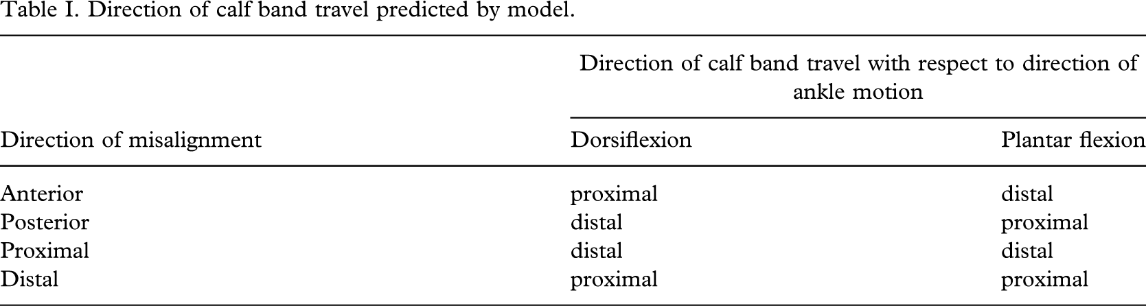
Misalignments in the anterior-posterior direction were found to have a much larger effect on the amount of proximal calf band travel than misalignments in the proximal-distal direction (Figure 4). For anterior misalignments, the model predicts that dorsiflexion movements cause the calf band to travel proximally and that plantar flexion movements cause the calf band to travel distally. Conversely, for posterior misalignments, the model predicts that dorsiflexion movements cause the calf band to travel distally and that plantar flexion movements cause the calf band to travel proximally. The model predicts that proximal-distal misalignments cause smaller magnitude movements of the calf band with consistent effects in both plantar flexion and dorsiflexion. In particular, proximal misalignments produce only distal movements of the calf band while distal misalignments produce only proximal movements of the calf band. These results are summarized in Table I.
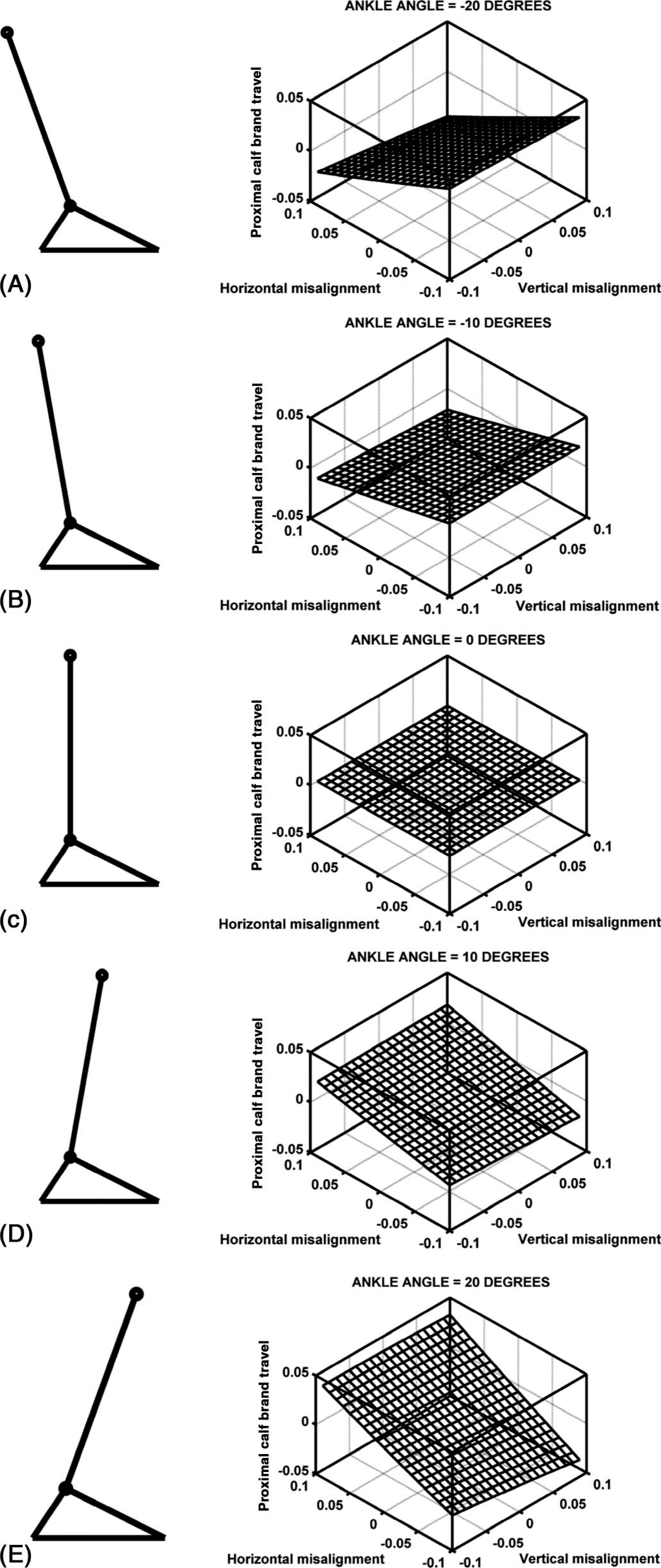
Proximal calf band travel for various amounts of anterior-posterior and proximal-distal misalignments of the mechanical ankle joints at five selected dorsiflexion angles (negative dorsiflexion angles represent plantar flexion angles): (A) −20°, (B) −10°, (C) 0°, (D) 10°, and (E) 20°. All measurements in the plots are normalized to the length of the shank and are referenced from a neutral dorsiflexion angle (as shown in (C)). Also, the length of the upright link was assumed to be 0.75 times the length of the shank. The calf band travel is more sensitive to anterior-posterior misalignments of the ankle than proximal-distal misalignments.
Direction of calf band travel predicted by model.
Similar results were found when examining independent misalignment effects (anterior-posterior only and proximal-distal only effects) using a typical able-bodied pattern of ankle motion during gait as an input (Figure 5). In early stance when the ankle is plantar flexing, posterior and distal misalignments would both cause proximal movements of the calf band with respect to its neutral position, whereas anterior and proximal misalignments would both cause distal movement of the calf band with respect to its neutral position. During the mid-stance portion of the gait cycle, the ankle is dorsiflexing from its neutral position. Therefore, anterior and distal misalignments would both cause proximal calf band movement, while posterior and proximal misalignments would both cause distal calf band movement. As was indicated in Figure 4, the effects of misalignments with similar magnitudes in the anterior-posterior direction have a much larger effect on calf band travel than misalignments in the proximal-distal direction.
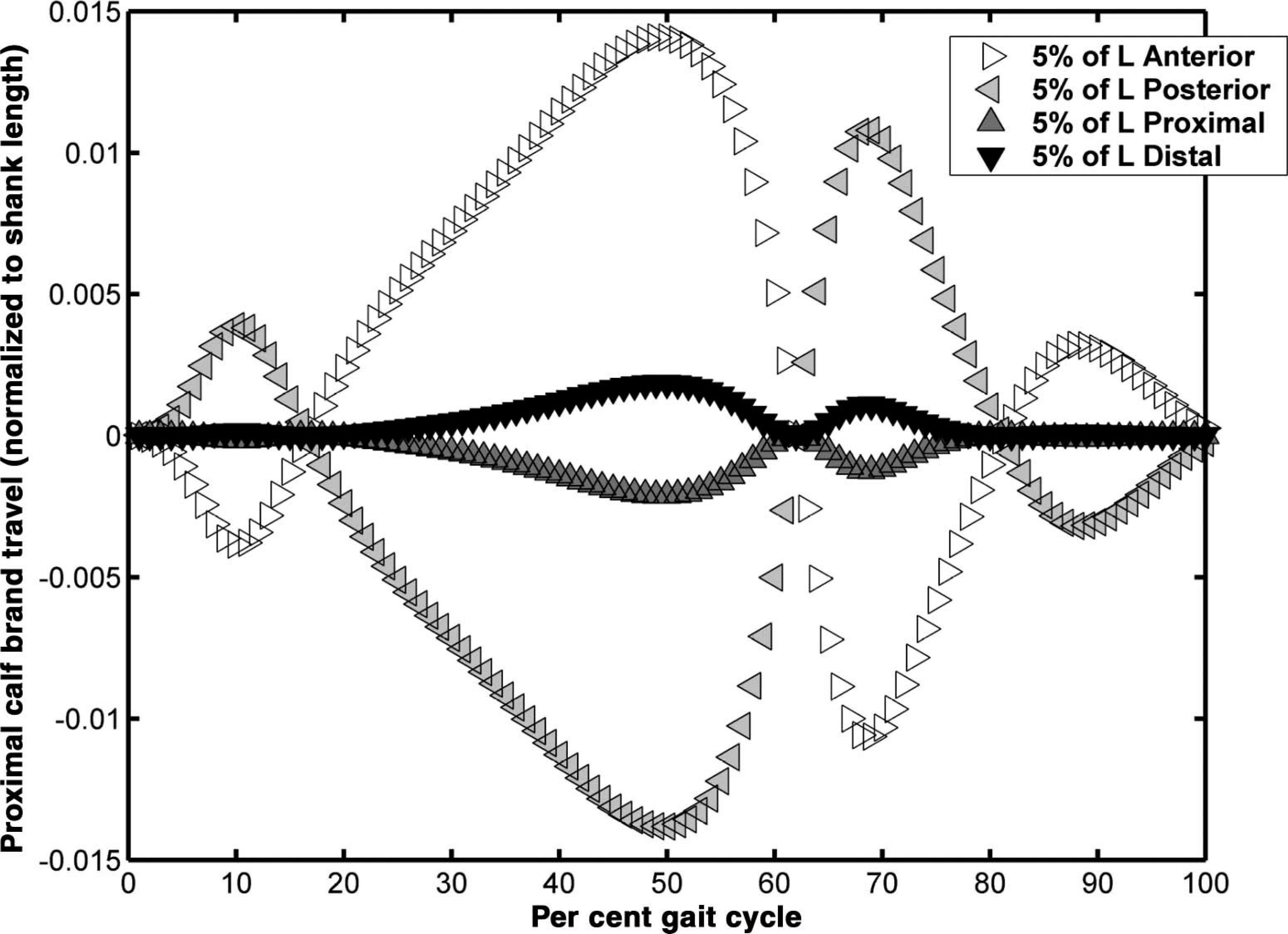
Proximal calf band travel (normalized to shank length) as a function of the gait cycle, using an average able-bodied ankle dorsiflexion curve as input. Anterior and posterior misalignments have opposite effects on the calf band travel. Proximal and distal misalignments also have opposite effects.
Discussion
Clinical observation (Rubin and Dixon 1973; Rubin and Danisi 1974), and mechanical (Lamoreux 1969; Sumiya et al. 1997) and computer models all support the idea that the calf band of an AFO does travel or piston when the ankle joint is misaligned and moved through a range of motion. The results of this simulation agree with the diagrams in the NYU manual (New York University 1974). Ankle joint axis misalignments within an AFO may be undesirable in instances where calf band travel would result in shear forces that compromise the integrity of the skin.
Lamoreux (1969) attributed calf band travel predominantly to anterior-posterior misalignment of their prototype dual-axis ankle joint. Similarly, Sumiya et al. (1997) found that the instantaneous centres of rotation of posterior-type polymer AFOs were always posterior to the anatomical ankle axis and concluded that the pistoning movements they measured between the calf band and the calf were due to this posterior positioning. The model presented in this paper for single axis mechanical joints indicates that calf band movement is more sensitive to misalignments in the anterior-posterior direction than in the proximal-distal direction. The effects of the small misalignments noted in the proximal-distal direction on calf band movement in the Sumiya et al. (1997) study were likely overshadowed by the effects of the anterior-posterior misalignments.
Ankle joint axis misalignments may lead to increased resistance to ankle joint motion. Bottlang et al. (1999) studied similar issues of axis misalignment using cadavers to identify a best-fit hinge position for the application of articulated external ankle fixation that minimized ankle motion resistance. The authors reported that the energy required to rotate the unconstrained ankle was negligible but was found to increase when external fixation was applied along a best-fit axis determined by them, and it increased even more for translational and angular misalignments from the best-fit axis of 5 – 10 mm and 5 – 10°, respectively. Translational misalignment of 5 mm from the best-fit axis doubled the mechanical energy compared to alignment with the best-fit axis for ankle rotations between 15° dorsiflexion and 25° plantar flexion. Distal misalignments of the mechanical joint axis required less energy than did proximal misalignments. Bottlang et al. (1999) suggested that the consequences of ankle axis misalignment included increased compressive forces at the articular surfaces and/or tension in the ligaments that constrain the ankle joint. They indicated that this would be likely to happen for articulated external fixation that imposes a horizontal hinge to the ankle joint when the best-fit axis was determined to be externally rotated and obliquely oriented. Since similar constraints apply to the alignment of single axis mechanical ankle joints used in orthoses (i.e., they must be aligned in order to function smoothly), there may be similar comparable consequences for the anatomical ankle joint and ligaments with use of an AFO.
In attempting to understand the consequences of these findings, two additional factors should be considered: the degree of friction at the interface between the calf band and leg, and the phase of the gait cycle. Assuming a large degree of friction at the interface between the calf band and leg, e.g., if the calf band is rigidly connected to the tibia, it would push the foot into the foot-plate when proximal misalignments are made and would pull the foot out of the foot-plate when distal misalignments are made. However, if friction is minimal and the phase of the gait cycle is considered, the opposite might occur. In reality, it is likely that the calf slides through the calf band when the axial load on the leg is above a threshold and “sticks” with the band when the load is below this threshold. Therefore, the actual response that would occur depends on loading and the angle of the joints when this threshold is crossed. Other factors that might affect this threshold include fit of the orthosis, presence and location of an ankle strap, degree of tension on ankle and calf straps, the type of interface material, the type of joint (single vs. multiaxial), and the type of shoe.
The ‘clinical rule of thumb’, which suggests that a slightly shorter stirrup be used in the event a correct length stirrup is unavailable, appears to be reasonable if minimal friction is assumed. Our model assumed that there was no movement between the foot and the foot-plate of the AFO, making it difficult to comment on the effect of calf band travel on the heel. In general, clinicians should be more concerned with anterior-posterior misalignments as they would tend to produce greater magnitudes of calf band travel. This finding has implications for the accuracy of the tibial torsion measurement since it is important to the determination of the anterior-posterior location of the ankle joints (Lehneis 1974).
Transverse plane misalignment between axes can cause binding and lead to restriction of motion, but the effect will depend on the degree of motion permitted at the joint. Lehneis (1974) predicted that transverse plane misalignment at the ankle joint would lead to unwanted pressures on the foot, patient fatigue due to increased resistance to joint motion caused by binding between the anatomical and mechanical axes, and increased wear of both joints, with resulting deformity of the anatomical joint and fatigue of the orthotic joints. The amount of joint motion that an AFO is permitted to provide, may also affect the outcome of axis misalignment. For example, if an AFO was designed to allow plantar flexion but restrict dorsiflexion, then our model would predict that for an anterior misalignment, the calf band would travel only during the loading response and early swing phase, limiting the effect of the misalignment. Bottlang et al. (1999) reported an exponential increase in the energy required to rotate a misaligned joint with increasing range of motion.
The results of the two-dimensional model presented here are limited to linear misalignments of single axis mechanical joints in the sagittal plane and their effect on calf band travel. The model assumes that there is no movement between the foot and the foot-plate of the AFO, and that misalignments cause only sliding of the calf band up and down the leg. In reality there can be movement of varying magnitude at the calf band interface and also between the foot and the lower portion of the articulated AFO. Motion of the AFO with respect to the leg might occur due to factors that the model does not consider such as strap tension, soft tissue movement, interface materials, extent of contact between the orthosis and the limb, and the overall fit (conformity) of the AFO. Some of these variables are unlikely to occur systematically and may alter the effect of ankle axis misalignments. Furthermore, the model does not predict the effect of angular axis misalignments on calf band travel or any other outcome variable, such as forces or moments applied to the leg by the calf band.
Further work is required to develop a three-dimensional model that can more completely analyse the many combinations of ankle axis misalignments possible in an AFO and their effect not only on calf band travel, but also on other variables such as ankle joint motion resistance and compressive forces at the articular surface. Further work is also required to develop predictive models of the effect of misalignment of joints at the knee and hip and multi-joint models that would allow us to analyse the impact misalignment of the ankle joint axis may have at the knee and hip and vice versa.
Conclusions
Sagittal plane misalignments of the mechanical and anatomical ankle joint centres within an AFO were simulated using a simple two-dimensional model. Misalignments in the anterior-posterior direction were predicted to have a much larger effect on the amount of proximal calf band travel than misalignments in the proximal-distal direction. The model presented in this paper for single axis mechanical joints predicts the proximal-distal direction of calf band movements reported by Sumiya et al. (1997) and the anterior-posterior direction of calf band movements reported by Lamoreux (1969), and supports the ideas proposed in the NYU manual (New York University 1974). In general, clinicians should be more concerned with anterior-posterior misalignments as they will result in greater magnitudes of calf band travel.
Footnotes
Acknowledgements
This work was funded by the National Institute on Disability and Rehabilitation Research (NIDRR) of the U.S. Department of Education under Grant No. H133E030030. The opinions contained in this publication are those of the grantee and do not necessarily reflect those of the Department of Education. The authors wish to acknowledge Michael Brncick for his insight and clinical guidance on this project.