
Abstract
Background: Articulated or hinged ankle-foot orthosis (AFO) allow more range of motion. However, quantitative investigation on articulated AFO is still sparse.
Objective: The objective of the study was to quantitatively investigate effects of alignment and joint types on mechanical properties of the thermoplastic articulated AFO.
Study design: Tamarack dorsiflexion assist flexure joints with three durometers (75, 85 and 95) and free motion joint were tested. The AFO joint was aligned with the center of the motor shaft (surrogate ankle joint), 10 mm superior, inferior, anterior and posterior with respect to the motor shaft center.
Methods: The AFO was passively moved from 20° plantar flexion to 15° dorsiflexion at a speed of 10°/s using a motorized device. Mechanical properties including index of hysteresis, passive resistance torque and quasi-static stiffness (at neutral, 5°, 10° and 15° in plantar flexion) were quantified.
Results: Significant effects of joint types and joint alignment on the mechanical properties of an articulated thermoplastic AFO were revealed. Specifically, center alignment showed minimum resistance and stiffness while anterior and posterior alignment showed significantly higher resistance and stiffness. The dorsiflexion assist torques at neutral position ranged from 0.69 ± 0.09 to 1.88 ± 0.10 Nm.
Conclusions: Anterior and posterior alignment should be avoided as much as possible.
The current study suggested that anterior and posterior alignment be avoided as much as possible in clinical practice due to potential skin irritation and increase in stress around the ankle joint.
Introduction
The ankle foot orthosis (AFO) serves as an exoskeleton and its alignment and mechanical properties are closely related to functional performance. 1 – 3 Various designs are available ranging from flexible to rigid ones and a wide range of materials (e.g. thermoplastic, carbon fiber, leather and metal) are used to fabricate AFOs. 4 – 6 Thermoplastic is popularly used in fabricating AFOs due to its low cost, light weight and ease of molding and maintenance. Thermoplastic usually demonstrates viscoelasticity 7 with major characteristics such as stiffness and hysteresis. Elasticity is an important and favorable feature which could serve as shock absorption and energy storage under loading. Given the same type of thermoplastic the stiffness is directly related to structure characteristics such as thickness of the wall, 8 and position of the trimline in solid AFOs. 9 – 11 In clinical practice, tremendous effort is made to align the joint of AFO with respect to the anatomical ankle joint (i.e. talocrural joint) as close as possible. The importance of the joint alignment was emphasized in the literature 2,12 and in the orthotic training manual. 4 However, there is still plenty of room for misalignment throughout procedures including casting, rectification and thermoforming. Misalignment could lead to consequences which might interrupt routine use of AFO including generating significant calf band motion, 2,4 putting stress on the skin and tissue underneath with potential risk to develop skin breakdown and tissue injury.
The importance of AFO mechanical properties has long been appreciated and its properties have been investigated via experimental and theoretical approaches. 11 – 15 Experimentally, both powered 14,16,17 and manually controlled 10 – 13 devices have been used. For instance, BRUCE, a manual mechanical device was developed to quantify the mechanical characteristics of AFOs including stiffness and neutral angle around the ankle and metatarsal-phalangeal joints. 12 Simiarly, a simple manual mechanical device was used to quntify the effect of ankle trimline in posterior-type plastic AFO. 10,11 Mechanical properties in three-dimensions were also quantifed. 18 – 20 Besides the experimental approach, theoretical methods, such as finite element method (FEM), have been used. Numeric approach is advantageous to an experimental one especially when investigating AFO characteristics under conditions which are not easy and/or possible to implement experimentally. For instance, stress distribution was successfully predicted during ambulation using FEM. 21,22 The relation between trim line location and AFO stiffness was also simulated in a non-linear finite element model. 23 A recent theoretical study using a simple model showed the ability to predict the displacement of the cuff band due to misalignment of AFO. 2
Articulated or hinged AFO allows more range of motion (ROM) compared to solid AFO 24 and its effect on improving gait is reported in studies on patients with spastic hemiplegic cerebral palsy 25 and stroke. 26 In addition, dorsiflexion assist is essential especially in patients with foot drop and difficulty in foot clearance. 27 However, quantitative investigation on articulated AFO is still sparse. In an earlier study on dorsiflexion assist flexure joint with durometer of 85 the authors showed that the joint alignment significantly affected the mechanical properties such as hysteresis and stiffness. 16 However, effects of joint types (either free motion or dorsiflexion assist flexure) were not investigated and the interaction between joint types and alignments remains unknown. The objective of this study is therefore attempting to quantitatively investigate the effects of various joint types and alignment and their interaction in an articulated AFO.
Methods
Experimental setup
A thermoplastic articulated AFO was fabricated using 3/16 inch polypropylene sheet by an experienced technician. The lower leg segment of the plaster mold without the foot part was salvaged and used as a surrogate leg. The surrogate leg was attached to a mounting jig with adjustable rods which allowed precise positioning in both horizontal and vertical directions (Figure 1). Dorsiflexion assist (DA) flexure (three durometers: 75, 85 and 95) and free motion joints (made of polyurethane, Tamarack Habilitation Technologies Inc, MN, USA) were selected due to their popularity and three samples were tested for each joint type. The joint was installed following the manufacture’s guidance. A motorized device with an inline torque sensor (Transducer Tech Inc, USA) and an optical encoder developed in an earlier study
16
was used to move the AFO in the prescribed ROM. The motor was controlled by a motor drive under speed mode in which both speed and direction of the motor rotation were modulated. NI USB-6215 M Series MIO DAQ was used for data acquisition and motor control and a custom graphical interface written in LabVIEWTM (National Instrument Inc, TX, USA) was used to set testing parameters including speed, ankle ROM and display registered signals. The data were sampled at a rate of 1,000 Hz.
Experimental setup.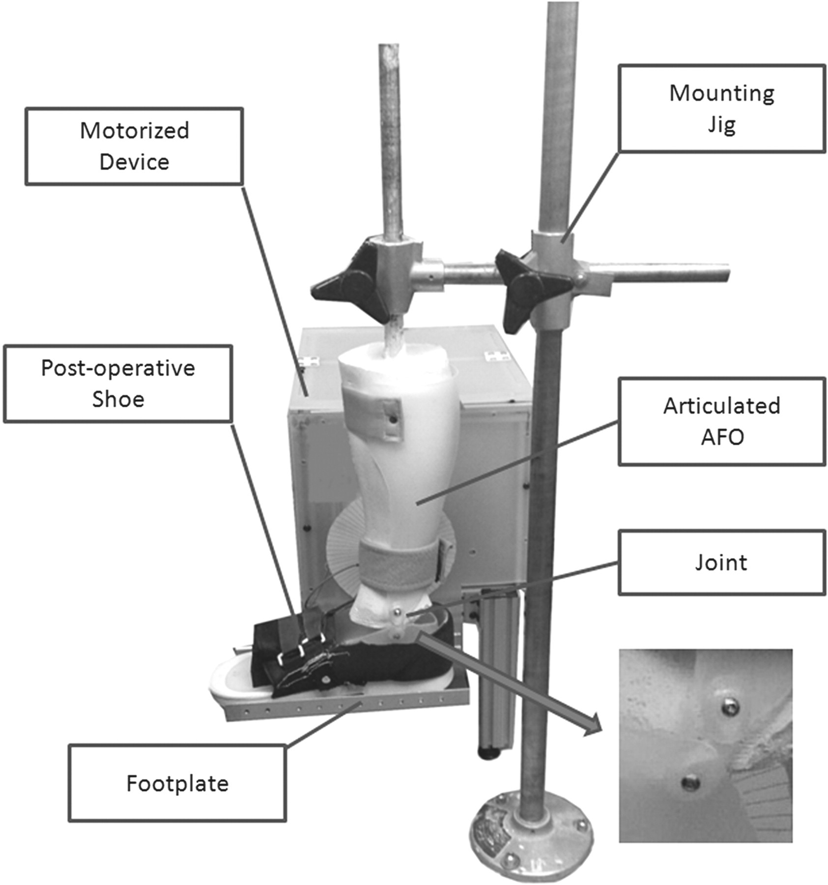
Experimental procedure
The AFO was donned on the surrogate leg, inserted in a modified post-operative shoe which was firmly attached to the footplate and secured via VelcroTM bands (Figure 1). The center of the motor shaft represented the anatomical ankle joint axis and the center of the mechanical joint of the AFOs was marked as the middle point between the centers of the two securing screws. The joint center of the AFO was changed systematically with respect to the center of the motor shaft (five positions in total: through the center of the motor shaft, 10 mm superior, inferior, anterior or posterior). When appropriate alignment was set the AFO was passively moved by the motor in a range from 20° plantar flexion to 15° dorsiflexion at a prescribed speed of 10°/s (the ROM was selected to match the averaged ROM in able-bodied ambulation 28 ). The resistance torque and corresponding angular position were registered via the uniaxial torque sensor and motor encoder at a rate of 1,000 Hz. Each test lasted 120 seconds and was repeated three times for each sample (three samples and four joint types) and position (five positions). In total, there were 180 trials.
Data analysis
The torque and position signals were digitally filtered using a fourth-order zero-lag low pass Butterworth filter with cutoff frequency set at 5 Hz. The main focus of the study was to investigate the mechanical properties of the AFO joints so the torque component attributed to the footplate due to gravity was subtracted from the original torque signal. The torque-angle relationship was plotted to establish the hysteresis loops (Figure 2). Index of hysteresis (a dimensionless quantity) was calculated as the ratio of the area within the loop to the area below the ascending limb and presented as a percentage (%).
29
Each hysteresis loop was further divided into an ascending limb (plantar flexion) and a descending limb (dorsiflexion) (Figure 2). The multiple ascending and descending limbs were pooled and averaged (n ≈ 16), respectively. As shown in Figure 2, the loading curves across cycles were consistent with little deviation. The consistency across loading cycles was evaluated using intraclass correlation coefficients (ICCs)
30
and the averaged ICCs for ascending and descending limbs across trials were 0.9999 and 0.9999 respectively indicating high consistency from cycle to cycle. The following mechanical properties of the joint were calculated based on the average ascending limbs of the torque-angle curve: passive resistance torque, quasi-static stiffness (first derivative of the torque-angle curve, i.e. the slope of the curve) at selected positions (especially under loading, e.g. neutral position, 5°, 10° and 15° in plantar flexion as illustrated in Figure 2) and index of hysteresis related to the viscoelastic properties of the joint.
Hysteresis loop in a typical trial (the selected positions on the loading curve are highlighted).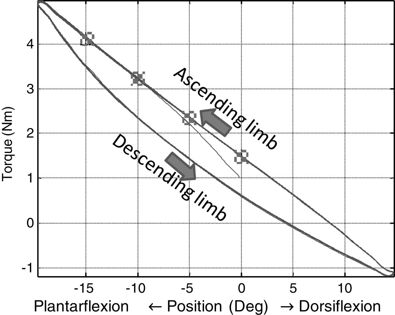
Statistical analysis
A two-way analysis of variance (ANOVA) was used to analyze the response variables including the resistance torque, stiffness and index of hysteresis with the joint types (four types: dorsiflexion assist flexure with three different durometers: 75, 85 and 95 and free motion), joint alignments (five positions: through the center of the motor shaft, 10 mm superior, inferior, anterior or posterior) and joint positions (neutral position, 5°, 10° and 15° in plantar flexion) as the factors involved. Tukey’s HSD (Honestly Significant Difference) test was used for post hoc comparisons. The significant level was set at 0.05. All statistics were conducted in MATLAB® statistics toolbox (MathWorks, Inc, Natick, MA, USA).
Results
Hysteresis index
Hysteresis index in percentage (mean [SD]).
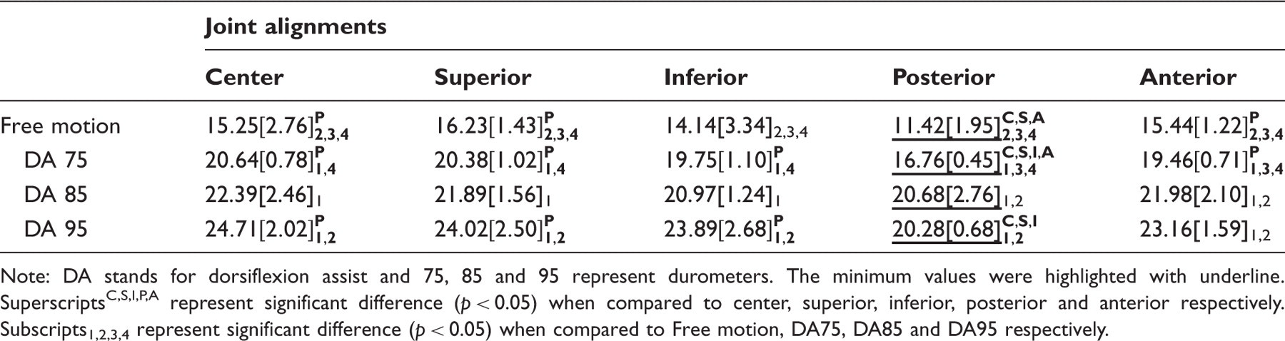
Note: DA stands for dorsiflexion assist and 75, 85 and 95 represent durometers. The minimum values were highlighted with underline. SuperscriptsC , S , I , P , A represent significant difference (p < 0.05) when compared to center, superior, inferior, posterior and anterior respectively. Subscripts1,2,3,4 represent significant difference (p < 0.05) when compared to Free motion, DA75, DA85 and DA95 respectively.
Resistance torque
Resistance torques at prescribed joint positions: neutral and 5°, 10° and 15° in plantar flexion (Nm, mean [SD]).
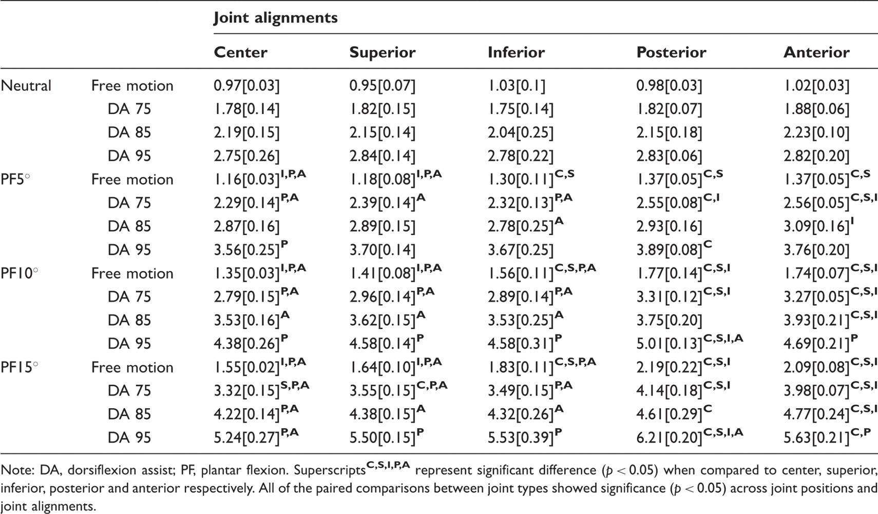
Note: DA, dorsiflexion assist; PF, plantar flexion. Superscripts
Quasi-static stiffness
Quasi-static stiffness at prescribed joint positions: neutral and 5°, 10° and 15° in plantar flexion (Nm.Deg−1, mean [SD]).
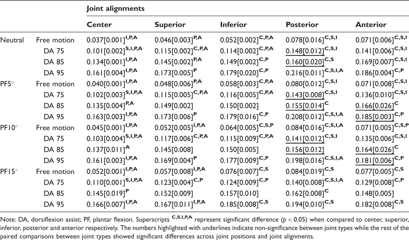
Note: DA, dorsiflexion assist; PF, plantar flexion. Superscripts
Discussion
Mechanical properties of solid AFOs have been examined extensively in the literature while quantitative studies on articulated AFOs are still limited. In the current study effects of joint types, joint alignment and joint positions on the mechanical properties of an articulated thermoplastic AFO were systematically investigated using a custom motorized device. Significant effects of alignments and joint types were revealed and their implications were discussed.
Hysteresis is associated with viscoelasticity and the index serves as a quantification of relative energy loss during unloading. 29 Our results showed that the hysteresis index was changed systematically with joint alignments and joint types. In general, free motion joint showed the lowest hysteresis indices across test conditions and the hysteresis increased slightly with the increase of durometer (Table 1). In addition, alignments affected the index to different levels. The lowest hysteresis index was associated with posterior alignment. The lower value could be attributed to the definition of the index. By definition the area under the curve was the denominator and the area within the loop was the numerator. The absolute averaged areas within the loop were comparable and did not differ from each other across alignments (e.g. 27.2 ± 2.5, 27.1 ± 2.4, 28.6 ± 1.9, 26.9 ± 2.1 and 27.9 ± 2.1 Nm.deg for center, superior, inferior, posterior and anterior alignments respectively for DA95). As shown in the results section the posterior alignment had higher resistance torque and stiffness which led to a larger area under the loading curve. Therefore it is mainly the difference in area under the curve which led to the difference in hysteresis indices among alignments.
In the current study, both resistance torque and stiffness were quantified and they changed systematically across test conditions including joint alignments, joint types and joint positions. Though resistant torque is one of the commonly used mechanical properties of AFOs, 14 joint stiffness is more informative about the change in resistance with respect to joint position. Mechanical properties of the AFOs are closely related to gait performance. 3,11,27,28,31 For the articulated AFO with dorsiflexion assist joint, the joint is loaded when plantar flexed (e.g. loading response and pre-swing) and recoils to assist dorsiflexion during initial swing. 28 The joint stiffness is related to the amount of energy stored during loading which, in turn, determines the amount of energy returned for dorsiflexion assist. 32 The current study shows that the dorsiflexion assist joint could be easily loaded during pre-swing because the resistance torque of the joint during plantar flexion were significantly less than a typical active peak ankle torque value (e.g. 1.36 Nm/kg 32 , or 102 Nm for a 75 Kg able-bodied person). 32 The dorsiflexion assist torque at neutral position ranged from 0.69 ± 0.09 to 1.88 ± 0.10 Nm, though relatively low, were sufficient to balance the passive ankle torque due to gravity and hold the ankle in neutral position (e.g. for a 75 kg able-bodied person, the mass of the foot is 1.45% of the body mass, 33 or 1.09 kg; the distance between the center of mass and the ankle joint is 42.9% of the segment length [from lateral malleolus to head of metatarsal II]; if the segment length is 12 cm, the moment arm is 5.15 cm and the passive moment of the foot induced by gravity is 0.55 Nm). Similarly, the plantar flexion resistance torques at neutral position ranged from 0.95 ± 0.07 to 2.84 ± 0.14 Nm and increased up to 5.24 ± 0.27 Nm for DA95. This level of resistance torque seems effective to control the plantar flexion during loading and avoid possible foot slap. However, due to a lack of consistent results on the ankle moment during loading response further investigation is needed to confirm this.
The resistance torques at neutral position were slightly lower than those reported in the Tamarack selection guide 34 (i.e. ranging from 1 to 6 Nm). The difference might be attributed to test protocol. In our study, the resistance torque and stiffness was quantified for the whole articulated AFO system which consisted of joint, AFO, plaster shank, foot plate and Velcro straps and the relative motion between components due to structural compliance (e.g. the Velcro strap) might reduce the resistance torque and stiffness.
Besides joint types and positions, joint alignments showed significant effects on the resistance torque and stiffness. With perfect joint alignment (i.e. coaxial) both joints move in synchronization and will not result in motion of the strap. Hence, the mechanical properties obtained at center alignment represented exactly those of the AFOs. However, when offset in alignment was introduced both resistance torques and stiffness were increased. Specifically, anterior and posterior alignment showed larger effect compared to inferior and superior alignments, and center alignment. An earlier attempt to interpret the structural dependency appeared in the orthotic manual from New York University in which the effects of joint alignment on calf band motion were illustrated using a simple yet informative geometric model. 4 The increased resistance due to misalignment was consistent with a cadaveric study in which energy required to move the ankle within a prescribed ROM with off-axis alignment, either translational or rotational, was increased. 35 The increased resistance might lead to a higher compressed force in the ankle joint and tension in ligament as suggested by Bottlang et al. 35 The increased resistance is closely related to calf attachment strap tightness. Previous studies have shown that misalignment of AFO ankle joint caused calf band motion across ROM. Securing the calf band more will lead to reduced relative motion but increased resistance while setting the calf band loose will result in increased motion but unappreciable changes in resistance. 36 In clinical practice, the calf strap needs to be fastened to accommodate the AFO to the patient body part and joint misalignment will inevitably lead to increased resistance torque. In addition, the tight coupling between calf band and skin might pose high shear stress with a potential risk of developing skin breakdown and tissue injury.
It should be noted that in the current study the mechanical properties were quantified for the whole AFO system without including a human ankle. The human ankle demonstrated hysteresis characteristic while passively loaded within ROM 37 and its joint compliance was also position dependent. 38,39 An attempt to investigate the properties on a human ankle with different types of AFOs was made in an earlier study. 14 However, there was a lack of investigation on the individual contribution from the human ankle and AFO and interaction in between in that study. In addition, joint alignment was not investigated and the challenge in aligning the mechanical joint with the ankle joint was not discussed. We believe a bottom-up approach (i.e. individual components first and then system) will improve our knowledge of articulated AFOs and provide useful clinical recommendation for practitioners. The current study was centered on the mechanical system and a future study will be conducted on investigating subject-dependent ankle properties and the interaction between the human ankle and AFOs.
Limitations of the study are acknowledged. Though thermoplastic articulated AFO is commonly used, conventional and solid AFOs are also prescribed and deserve detailed investigations. In this study one single movement speed at 10° per second was selected to approximate the average speed during ambulation and a large range of speeds needs to be investigated in a future study. The ankle angular speed varies throughout a typical gait cycle 28 and motor driven under position control will better mimic the ankle angular kinematics in a gait cycle.26−29 The tension of the strap might affect the tested results. In the current study, all the Velcro straps were pulled as hard as possible to secure and a control on tightness might help produce more consistent results. In addition, the AFO was donned directly on the plaster mold which lacks the soft tissue in a human subject. Ankle motion is tri-planar and similar protocol might be repeated for quantifying mechanical properties in frontal and transverse planes in future studies.
Conclusion
Significant effects of joint types and joint alignment on the mechanical properties of an articulated thermoplastic AFO were revealed. Specifically, optimal alignment showed minimum resistance and stiffness while posterior and anterior alignment showed significantly higher resistance and stiffness. It is recommended that anterior and posterior alignment be avoided as much as possible due to potential skin irritation and increase in stress around the ankle joint. In addition, the dorsiflexion assist torque (e.g. ranging from 0.69 ± 0.09 to 1.88 ± 0.10 Nm at neutral position) provides quantitative evidence that the dorsiflexion assist joint is effective in assisting the ankle dorsiflexion which facilitates toe clearance in swing phase.
Footnotes
Acknowledgement
We would like to thank Tamrack Habilitation Technologies, Inc for joint samples used in the study and Mr Miguel Mojica for his comments.
Funding
This work was supported by the American Heart Association [grant number 09SDG2080460].