
Abstract
Fluid inserts potentially help to overcome prosthetic fit problems resulting from stump volume change. The purpose of this investigation was to add fluid to fluid inserts positioned on the inner socket walls of trans-tibial prostheses and to assess their influence on socket stresses. Pressures and shear stresses were measured at 13 sites on the sockets of two trans-tibial amputee subjects while they ambulated at their self-selected walking speeds. Stresses at the transducer sites generally increased with greater fluid addition and, interestingly, both subjects found relatively high fluid insert volumes most comfortable. The magnitudes of stress change were larger than those resulting from alignment, cadence, and componentry changes as reported in the literature. Possible explanations for why subjects found settings that induced higher measured socket stresses more comfortable than those that induced lower measured stresses include: A reduced shear: pressure ratio; the short duration of the study; and reduced stresses at sites not monitored with transducers.
Introduction
Changes in the fit of a lower-limb prosthetic socket over time are a challenge for many prosthesis-users. A poor socket fit can induce gait instability and skin breakdown (Hoaglund et al. 1983; Levy 1980). Shape and volume changes in the stump are considered a primary source of fit problems (Fernie and Holliday 1982; Commean et al. 1998). Both daily changes and long-term changes over weeks or months can occur.
Improving fit by adding or removing material from the limb-socket interface can help to reduce problems arising from limb changes. One approach is to add stump socks to accommodate volume loss. Stump socks are often added over the course of a day, for example. However, the prosthesis must be removed to add the socks, and material is added uniformly to the interface, not necessarily in the correct locations to accommodate the shrinkage. Inflatable inserts are another option; they are air-filled sacks positioned in the socket with a tube extending through the wall to a pump. The user pumps up the insert to accommodate volume loss. However, most designs have a very small range of volume accommodation (Sanders and Cassisi 2001), limiting their versatility. A related option is fluid inserts, thin fluid cells extending proximally to distally along the inside socket wall. Fluid inserts are expected to be better than air-inflated inserts because the fluid is incompressible. Air-filled inserts are too soft except at moderate to high pressure settings, and they do not expand much over the moderate to high pressure range. These features mean that air-filled inserts cannot perform effectively over a wide range of limb fluid volumes, unlike fluid-filled inserts that can accommodate a broad range of limb volume changes. Fluid-filled inserts should thus have a wider range of volume accommodation.
The purpose of this study was to add fluid to fluid inserts positioned on the inner socket wall and to assess the effects on socket pressures and shear stresses. Two trans-tibial amputee case studies are reported. The authors hypothesized that as the inserts were filled to their comfortable or optimal size, socket stresses would distribute more uniformly across the inside of the socket. In other words, it was expected sites of high pressure and shear stress would decrease and sites of low pressure and shear stress would increase.
Methods
Two male subjects with unilateral trans-tibial amputations participated in this research. Subject #1 was 60 years of age, 1.8 m height, and 107 kg mass. His right lower limb was amputated as a result of traumatic injury 6 years prior. One year after his amputation he was diagnosed with Type II diabetes mellitus. His current prosthesis was of endoskeletal design – total surface-bearing socket, 9 mm Alpha Cushion liner, suction suspension (Ohio Willow Wood, Sterling, OH), and a cadence HP foot (Seattle Limb Systems, Poulsbo, WA). Subject #2 was 37 years of age, 1.8 m height, and 81 kg mass. His left lower limb was amputated as a result of traumatic injury 10 years prior. His current prosthesis was of an endoskeletal design, with a total surface-bearing socket, suspended with a 9 mm locking Alpha liner.
The instrumented prostheses were different from the subjects' usual prostheses. A different socket was necessary because the use of a gel liner would interfere with the pressure/shear transducers. The sockets, designed and fabricated by the research prosthetist, were hard sockets of PTB design with a 1 – 5 ply sock fit. They were made at least one year prior to the study. Since both subjects had undergone stump volume loss from when the sockets were made, the fits were loose when no fluid was in the fluid inserts. This situation was ideal for this study so that the effects of adding fluid to the inserts could be evaluated.
A custom load cell (Berme et al. 1976) a pyramid socket adaptor, a 30 mm aluminum pylon, and a Seattle LiteFoot (Seattle Limb Systems, Poulsbo, WA) completed each prosthesis. Subjects wore tennis shoes (Saucony Grid, Peabody, MA) during testing.
Two fluid inserts (provided by Simbex, Lebanon, NH) made of medical grade polyurethane, each of dimension 140 mm length and 46 mm average width (64 mm maximum width) (Figure 1a), were affixed to the inner socket surface with double-stick tape. The inserts were teardrop-shaped with the large end positioned proximally and the narrow end positioned distally. The inserts were positioned posterior laterally and medially over the gastrocnemius and soleus muscles. These locations were selected because they were acceptable to the clinical research prosthetist in that they were over muscle and thus did not alter socket shape over the bony protuberances of the tibia, they were comfortable to the subjects, and did not interfere with the interface stress transducers. A ‘Y’-connector to both inserts was attached to a 3 mm OD plastic tube that extended through a hole in the distal socket wall. The hole was sealed such that the pressure difference across the socket wall was maintained. This set up allowed a fixed amount of fluid (diluted propylene glycol) to be easily added or removed from the system using a syringe connected to a luer lock on the plastic tube. It is important to note that the Simbex Active Control System™, a commercial mechanical control system that continuously regulates the amount of fluid within the inserts, was not used in this study. The reason was that the purpose of this study was to determine if socket stresses were affected by small volume additions to the inserts. If the Simbex system, which continuously changes insert fluid volume based on the insert pressure, were used then such investigation would not be possible. If a systematic socket stress/fluid insert volume relationship were demonstrated here then a next step would be to test the Simbex system.
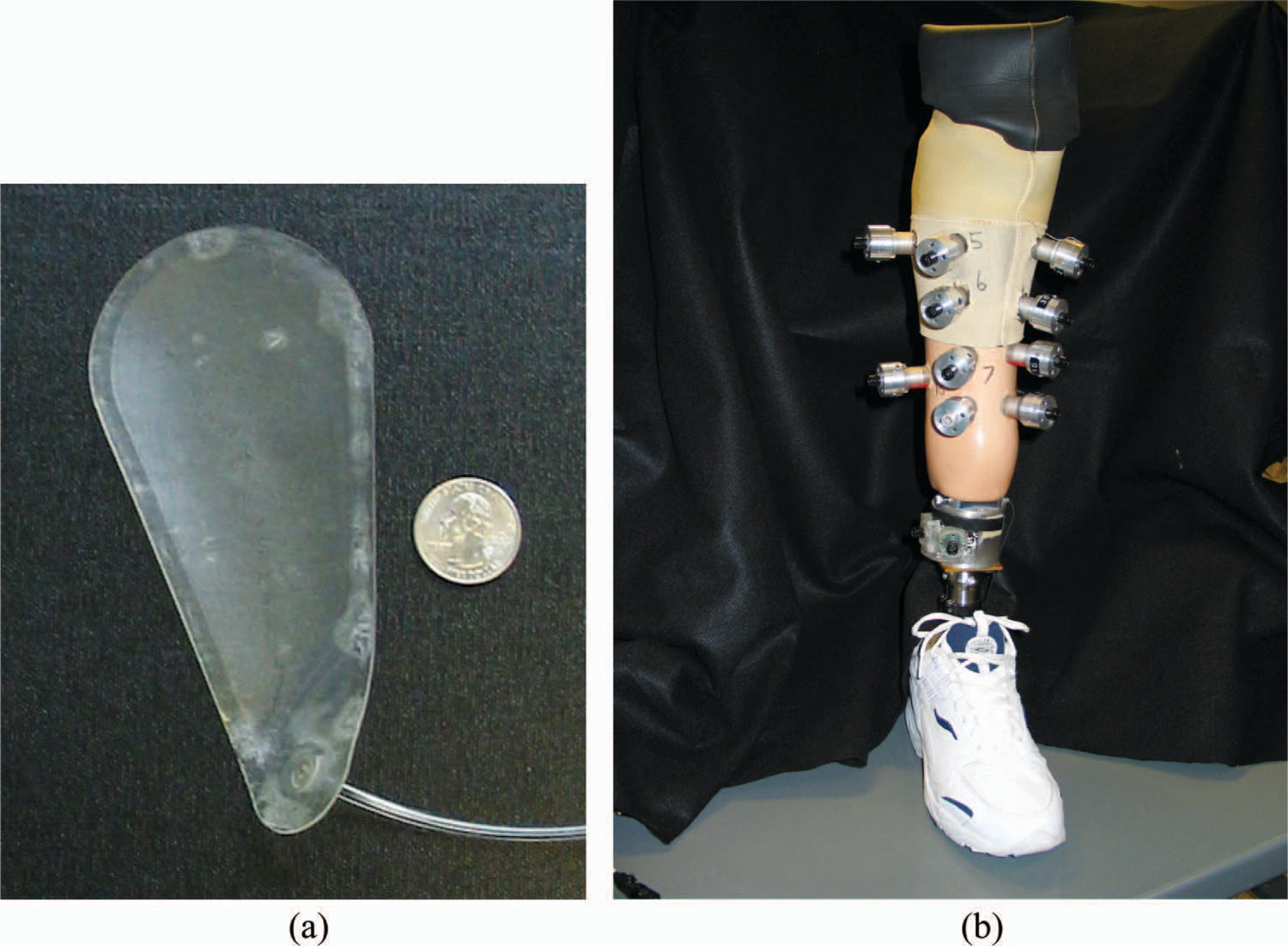
Instrumented socket with fluid inserts. (a) Polyurethane inserts were used in this study. (b) Thirteen transducers were positioned on each socket (posterior transducers not visible). Thin cables extending from the transducers to a fanny pack are not shown. See Table I for descriptions of transducer sites. Two inserts were positioned on the inside socket surface.
Thirteen transducers were positioned in mounts affixed to the socket wall (Figure 1b) using techniques as described in detail previously (Sanders et al. 2005). The transducers were positioned at the locations listed in Table I. No transducers were placed over the fluid inserts. The total mass added to the socket by the instrumentation was 320 g.
Sites of interface stress measurement (see Figure 1 for image of instrumented socket).
Thin, lightweight 2.75 mm diameter cables extended from each transducer to a fanny pack (of mass 1.8 kg) housing signal conditioning and digital multiplexing instrumentation. An 18.5-m long cable extended from the fanny pack to a stationary computer data acquisition system (450 MHz Dell Optiplex PC, Round Rock, TX; MIO-16XE-10 A/D board, National Instruments, Austin, TX).
For each subject a preliminary test was conducted a few days before the data collection session to determine the subject's self-selected walking speed (Mitchell and Sanders 2000) and the acceptable fluid volume ranges for the fluid inserts. No interface stress data were collected during these initial tests. Subject #1's preferred walking speed was 1.1 m/s; he was able to walk with 0 ml to 56 ml of fluid in the inserts. Subject #2's preferred walking speed was 1.7 m/s; he was able to walk with 10 ml to 28 ml of fluid. At the 10 ml setting Subject #2 noted that he felt some discomfort distally from end-bearing.
When each subject arrived for a data collection session, he first sat comfortably wearing his regular prosthesis for 10 min. He then donned the instrumented prosthesis and walked two passes of a 20.8 m hallway while the research prosthetist made minor alignment adjustments to the prosthesis. Trials with data collection were then started. Initially, the fluid level in the inserts was at the lowest end of the subjects acceptable range. The subject walked two passes at a walking speed ±7% of his natural walking speed while socket stresses were monitored (175 Hz sampling rate, 30 s sampling interval). Trials with speed that varied by more than 7% of the self-selected were discarded. Two, 4, or 8 ml of fluid was then added to the fluid inserts and an additional two trials conducted. This process was repeated, adding or removing fluid from the inserts, until all of the fluid volume levels (eight for Subject #1, six for Subject #2) were tested. The duration of the two trials at each setting was approximately 2.4 min.
Data were processed to extract only the stance phase portion of each step during the central 11 – 12 steps (of approximately 16 steps) of each trial. Axial force data from the pylon load cell was used to identify initial contact and terminal stance. The maximal pressure and shear stress at each site for each step were determined and tabulated. In the results presented below, shear stress is defined as the resultant force in the plane of the transducer divided by the transducer surface area. At least 22 steps were analysed at each fluid volume setting.
Results
For Subject #1, peak socket pressures during stance phase ranged from 32.6 – 305.2 kPa, and peak shear stresses ranged from 0.3 – 50.5 kPa. Variability (standard deviation/mean) averaged 4.5% for pressure and 10.3% for shear stress. The mean difference in maximal minus minimal peak stress at each site over the fluid insert volume range averaged 40.4 kPa (33.1% increase) for pressure and 5.1 kPa (60.4% increase) for shear stress. For Subject #2 socket pressures ranged from 33.4 – 249.8 kPa, and shear stresses ranged from 1.7 – 61.3 kPa. Variability averaged 7.4% for pressure and 17.3% for shear stress. The mean difference in maximal minus minimal peak stress at each site over the fluid insert volume range averaged 20.9 kPa (18.1% increase) for pressure and 5.5 kPa (41.5% increase) for shear stress. Both subjects complained of discomfort in the anterior mid-limb region when the inserts were filled to the highest fluid level (56 ml for Subject #1; 28 ml for Subject #2).
Subject #1
In general, stresses increased with increased fluid volume. The mean pressure at all sites increased over the 0 ml to 56 ml range (Figure 2). Mean shear stress was maximal at the 48 ml setting, a setting the subject found very comfortable. The range of peak pressures (magnitude at site of maximum pressure − magnitude at site of minimum pressure) also increased over the volume range (Figure 3), from a low of 179.2 kPa at 0 ml to a high of 272.6 kPa at 56 ml. Thus pressures did not approach a consistent mid-range value across sites with increased fluid volume. Instead, the opposite occurred. The range of pressures across sites increased with increased fluid volume.
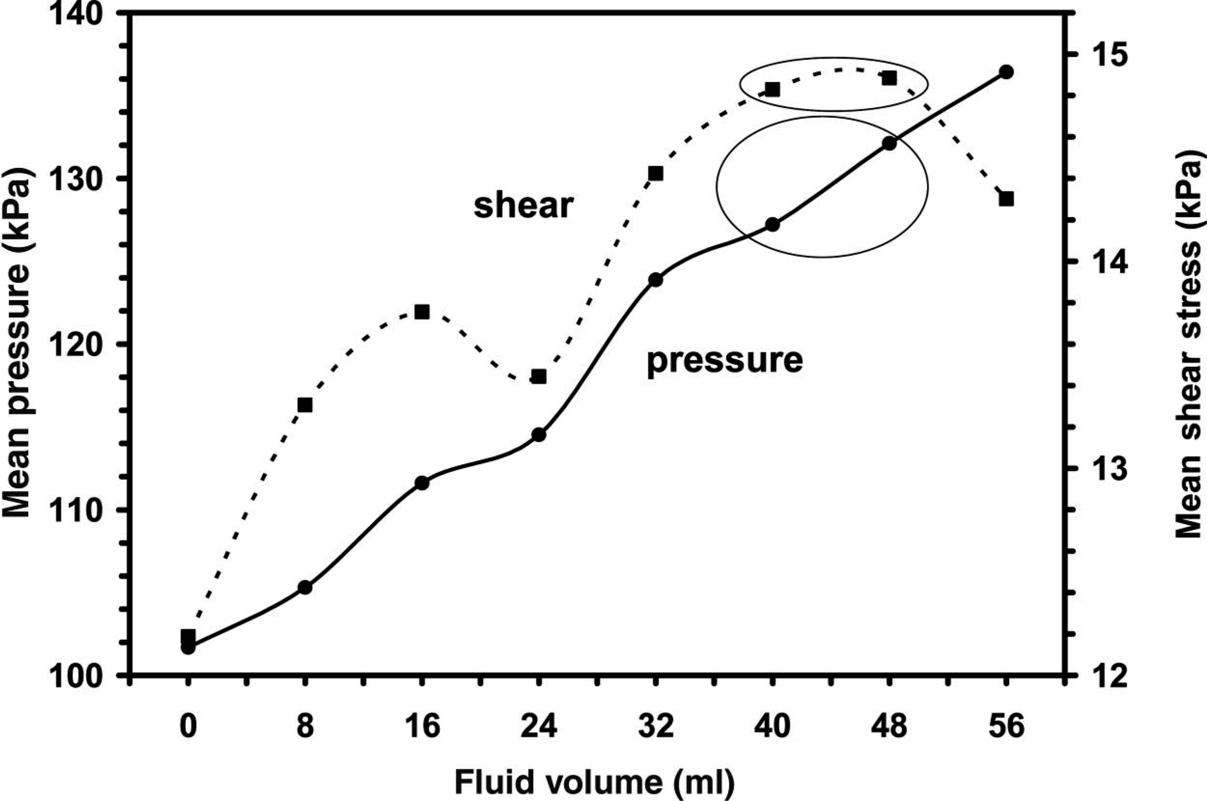
Change in mean socket pressures and shear stresses with increased insert fluid volume – Subject #1. Each point represents the mean from the 13 transducer sites. The subject found the 40 ml and 48 ml settings (circled) most comfortable. In general, socket stresses increased with increased fluid volume.
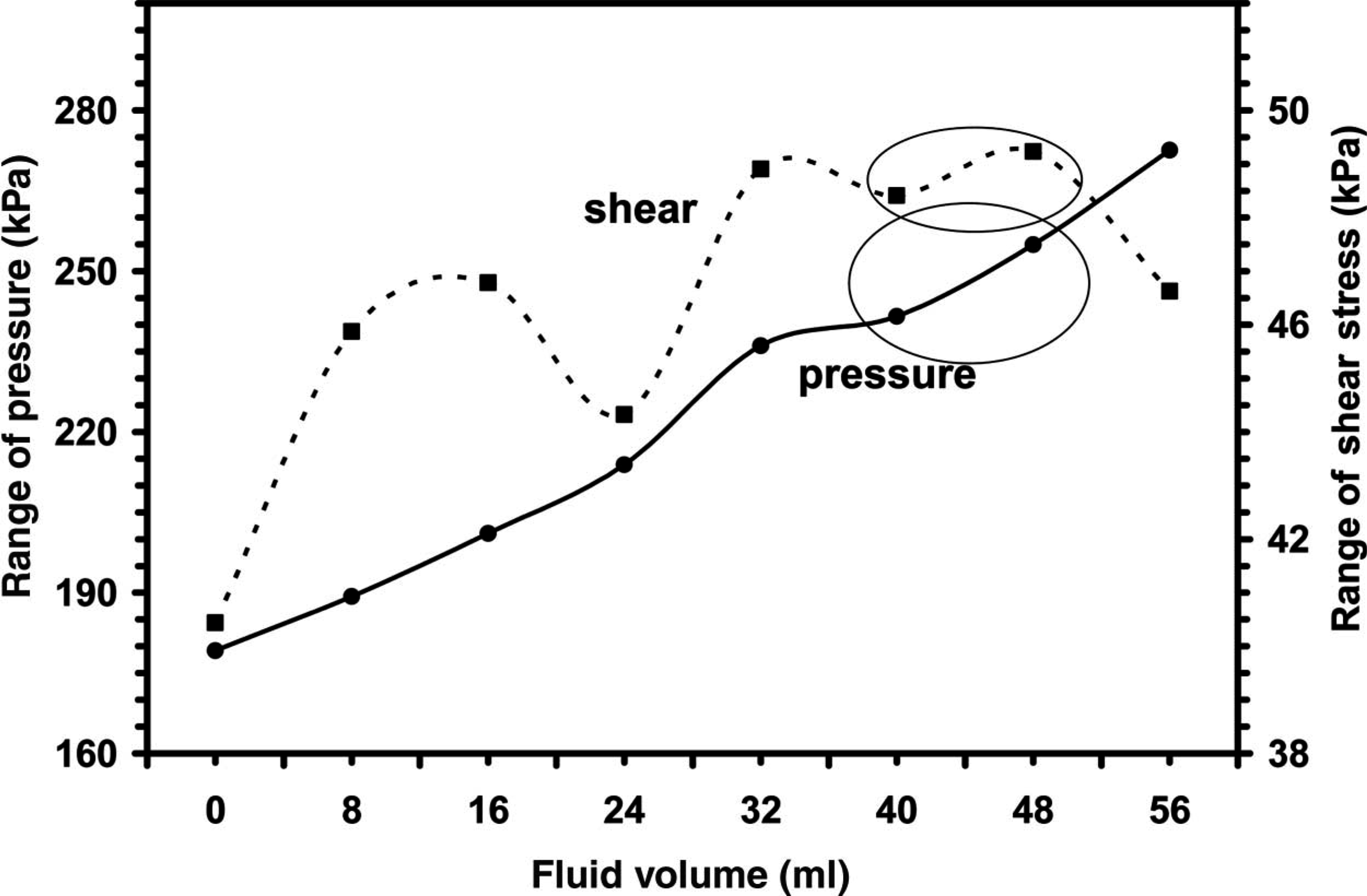
Change in the ranges of socket pressures and shear stresses across transducer sites with increased insert fluid volume – Subject #1. The range at each fluid setting (magnitude at the site of maximum stress minus magnitude at the site of minimum stress) is shown. In general, the range increased with increased insert fluid volume.
Stress changes varied by region. Pressures at all distal sites (anterior-medial distal, anterior-lateral distal, lateral distal, and posterior distal) increased from fluid volumes of 0 ml to 40 ml (Figure 4a). 40 ml and 48 ml were the settings most comfortable to the subject. The pressures at those sites were then more stable from 40 – 56 ml. At anterior-medial mid-limb proximal and distal sites, the opposite trend was seen – pressures were more constant from 0 – 40 ml than from 40 – 56 ml. Other mid-limb sites (anterior-lateral mid-limb proximal and distal, posterior mid-limb) increased consistently in pressure over the entire 0 – 56 ml range. At all proximal sites (anterior-medial proximal, anterior-lateral proximal, lateral proximal, and posterior-proximal) pressures were relatively stable from 0 – 40 ml, then decreased from 40 – 56 ml. Thus for Subject #1 as fluid volume was increased from 0 ml, first distal pressures increased and then mid-limb pressures increased. The proximal sites were relieved at the very high fluid levels.
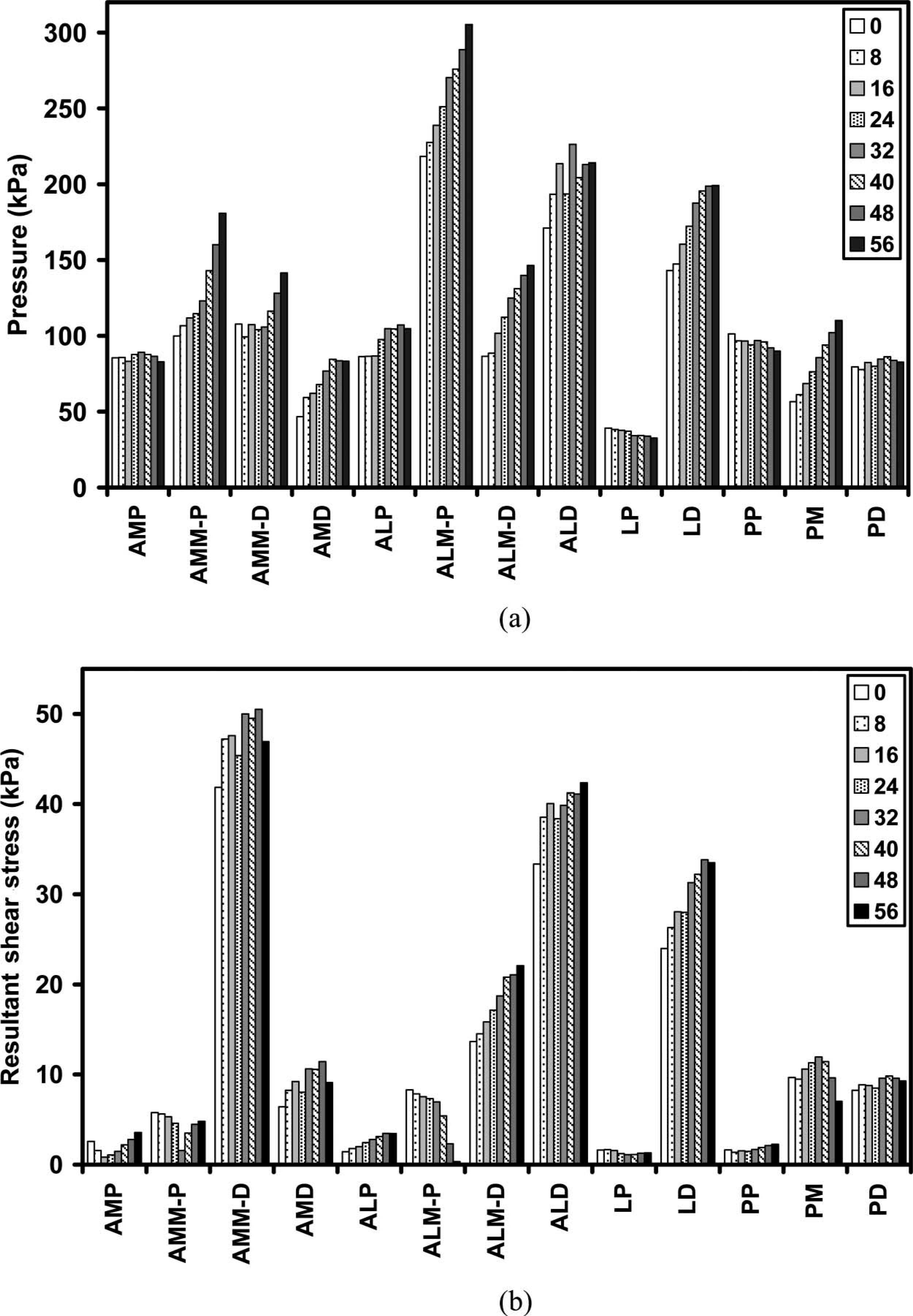
Comparison of socket pressures and shear stresses at different insert fluid volumes – Subject #1. Mean stresses for all steps at a setting are shown. Abbreviations for the transducer sites are listed in Table I.
The increases in pressure at mid-limb sites for the 40 – 56 ml settings were coupled with decreased shear stress or less increase in shear stress compared with the 0 – 40 ml change at most of those locations (Figure 4b). Thus at mid to high fluid insert volumes, the ratio of shear stress to pressure decreased with increased fluid volume (Figure 5).
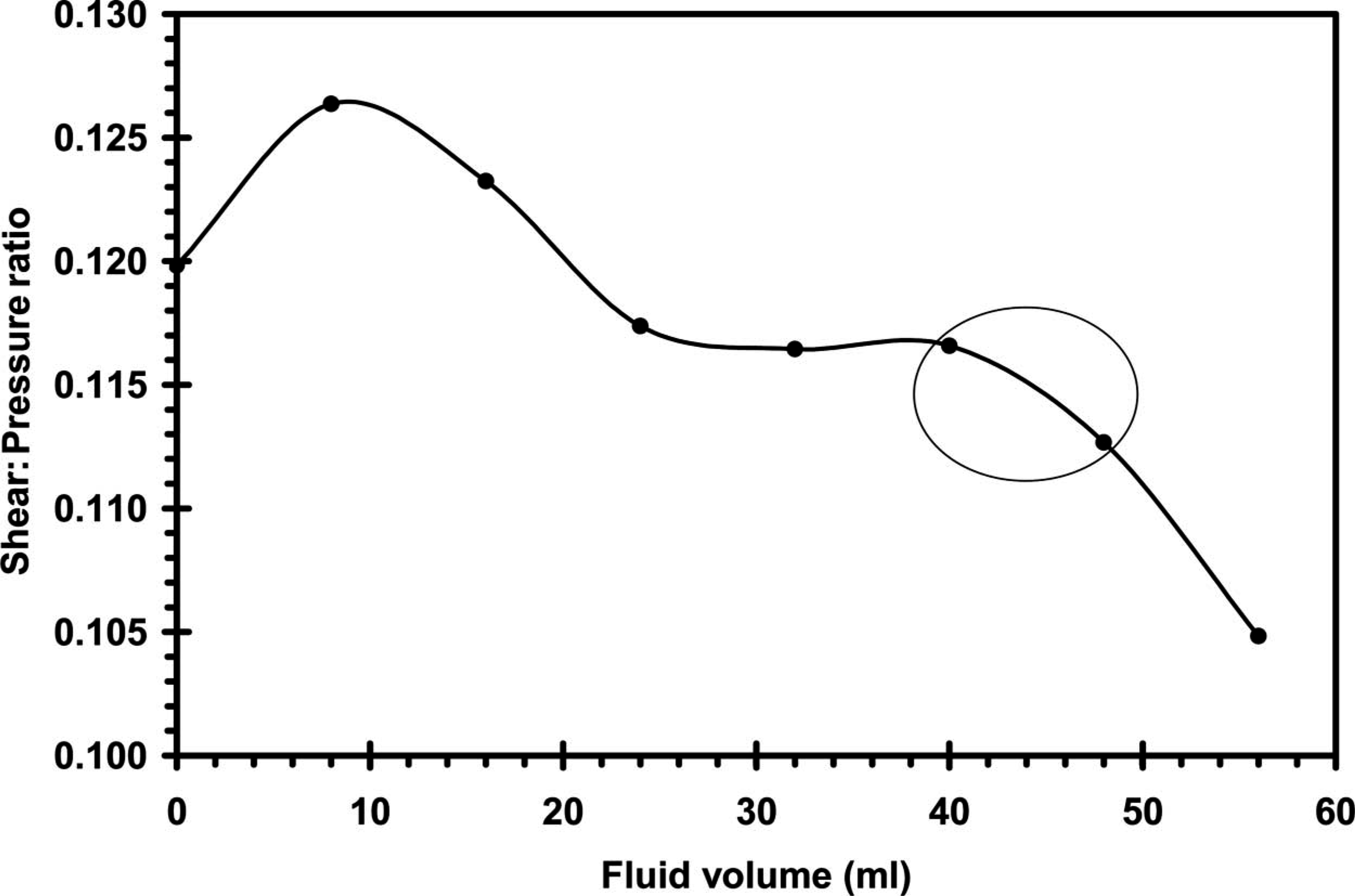
Mean ratio of shear stress to pressure at different insert fluid volumes – Subject #1. The mean ratio was low at the preferred insert fluid volume settings.
Subject #2
For the second subject, pressures generally increased with increased fluid volume, maximizing at 24 ml for pressure and 20 ml for shear stress (Figure 6). The range of pressures decreased, however, over the 10 – 28 ml fluid range and was at a low of 163.2 kPa at 28 ml (Figure 7). The shear stress range was at a low of 47.5 kPa at 28 ml.
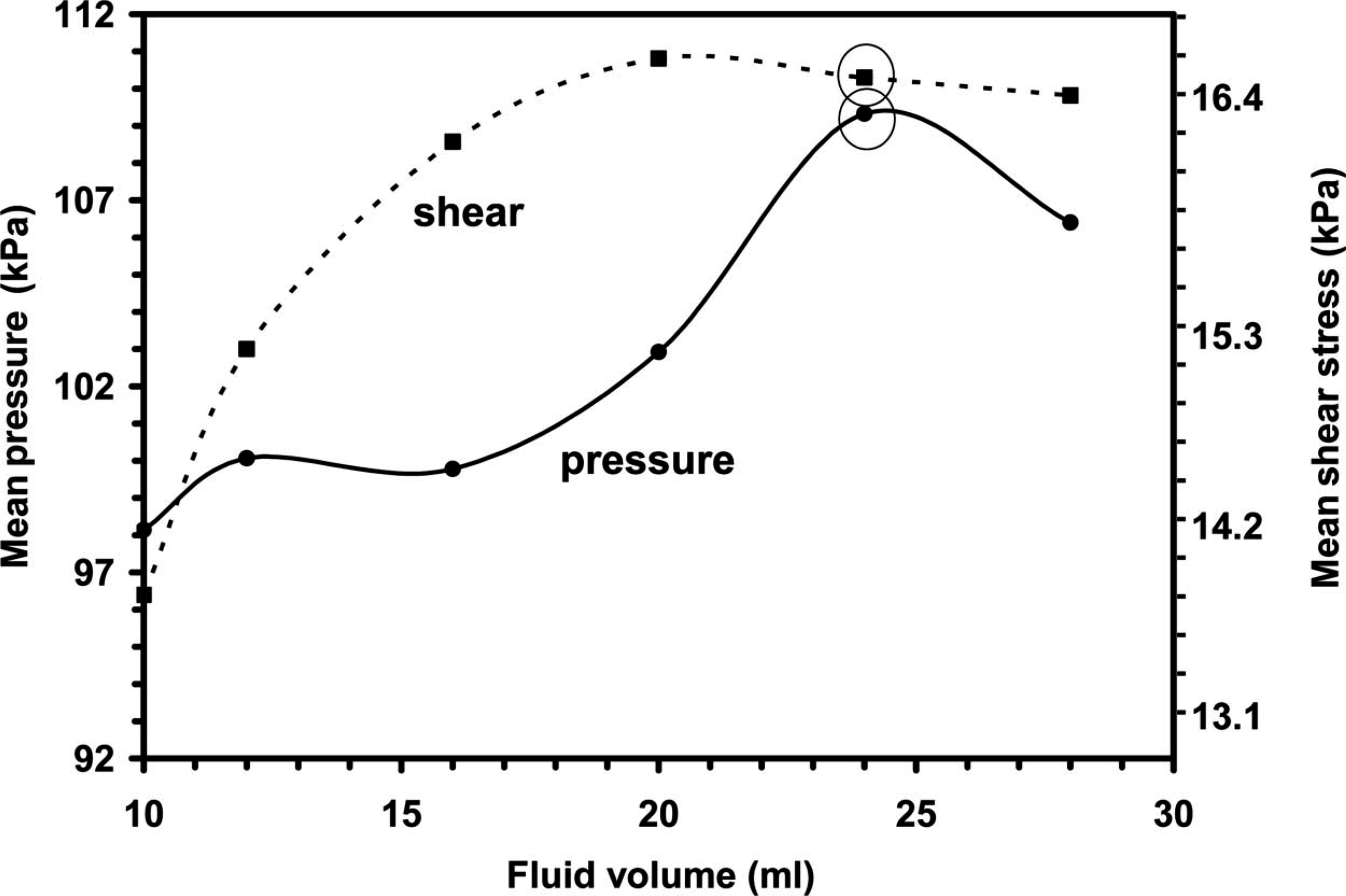
Change in mean socket pressures and shear stresses with increased insert fluid volume – Subject #2. Each point represents the mean from the 13 transducer sites. The subject found the 24 ml setting (circled) most comfortable. In general, socket stresses increased with increased fluid volume.
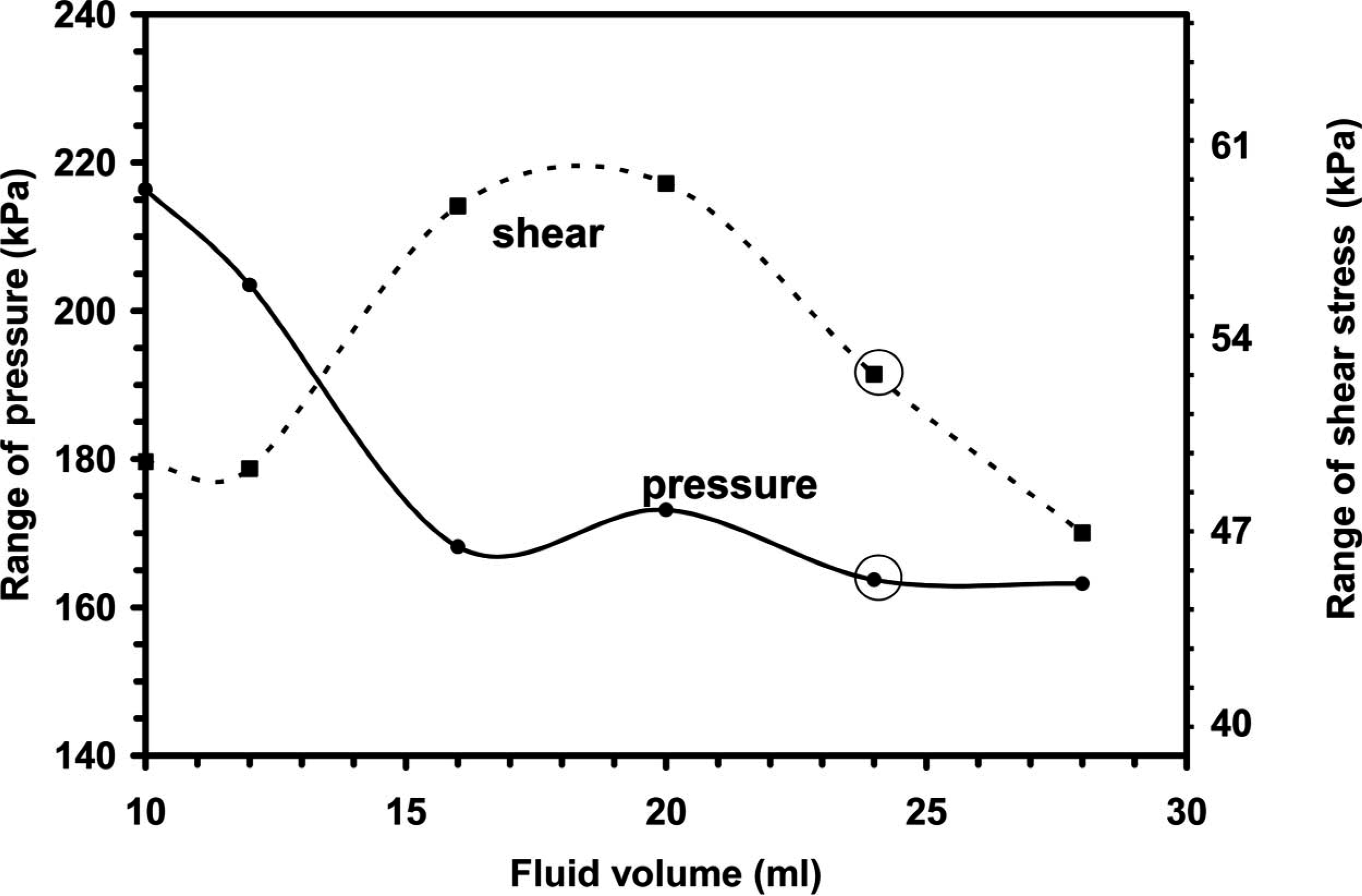
Change in the ranges of socket pressures and shear stresses across transducer sites with increased insert fluid volume – Subject #2. The range at each fluid setting (stress at the site of maximum stress minus the stress at the site of minimum stress) is shown. In general, the range decreased with increased insert fluid volume.
Stress changes varied by region. Pressures decreased at the site of maximal pressure (anterior-lateral distal) with increased fluid while other sites generally experienced pressure increases. Interestingly, at the perceived optimal fluid volume (24 ml) the pressures maximized at most of the sites (Figure 8a).
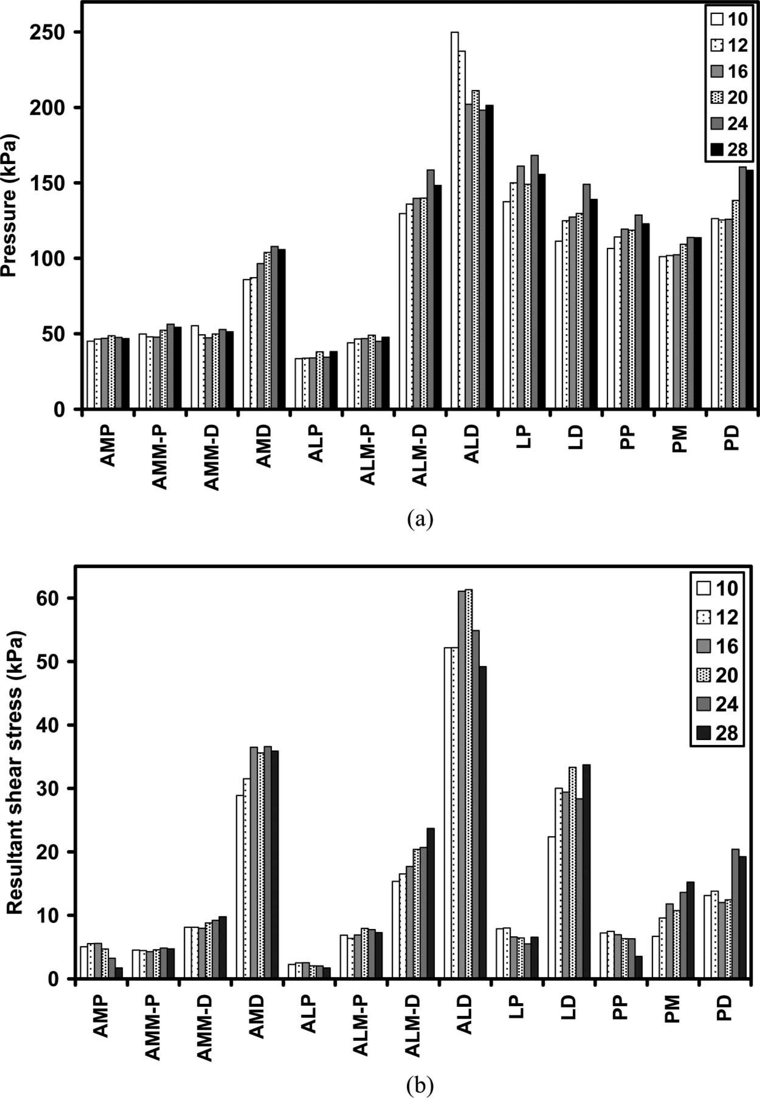
Comparison of socket pressures and shear stresses at different insert fluid volumes – Subject #2. Mean stresses for all steps at a setting are shown. Abbreviations for the transducer sites are listed in Table I.
Shear stresses increased in the mid-limb region as fluid volume was increased. Anterior-medial mid-limb-distal, anterior-lateral mid-limb-distal, lateral distal, and posterior mid-limb sites all showed increased shear stress with increased fluid volume (Figure 8b). Proximal shear stresses (anterior medial proximal, anterior lateral proximal, lateral proximal, posterior proximal), however, decreased with increased fluid volume. Shear stresses at many of the sites (anterior-medial proximal, anterior-medial mid-limb-proximal, anterior-medial-distal, anterior-lateral proximal, anterior-lateral mid-limb proximal, anterior-lateral distal, posterior proximal, and posterior distal) decreased from the perceived optimal insert setting of 24 ml to the highest volume setting of 28 ml. Thus the ratio of shear stress to pressure was at a local minimum at the preferred fluid insert volume (24 ml) (Figure 9).
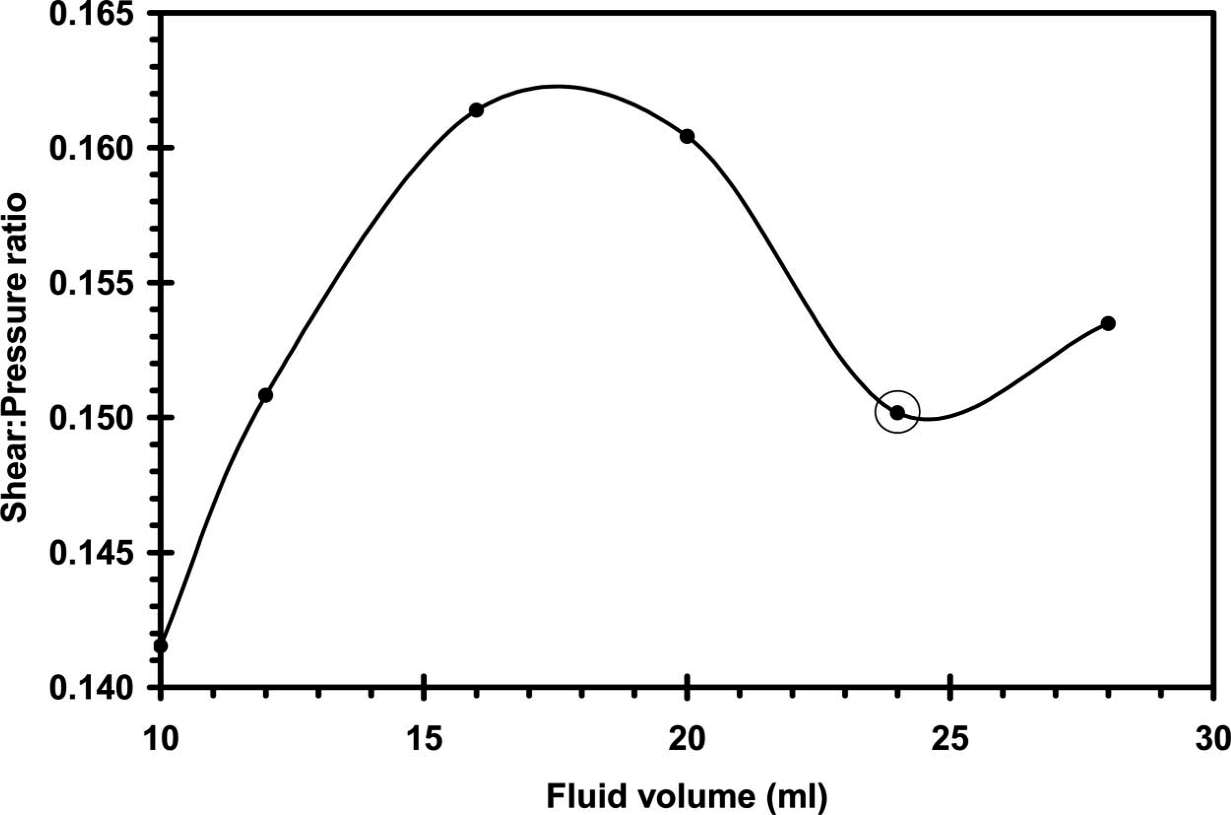
Mean ratio of shear stress to pressure at different insert fluid volumes – Subject #2. The mean ratio was low at the preferred insert fluid volume setting.
Discussion
Fluid inserts potentially help to overcome prosthetic fit problems resulting from stump volume change. Fluid added to the inserts is intended to replace fluid that exits the stump over time. The intent of this research was to investigate if fluid inserts had an effect on socket pressures and shear stresses, and if so if the trends were consistent with their expected means of function.
Features of our study design are important to consider towards interpretation of the data. The time interval of the investigation was relatively short. The trials conducted at each fluid volume setting typically did not take more than a few minutes to collect. This was done so as to isolate the influence of filling the fluid inserts, as opposed to assessing limb fluid loss over the course of the session. Since variability in the data (standard deviation/mean) was not appreciably different from that reported in other studies using the same instrumentation investigating other parameters (Sanders et al. 1998, 2000, 2005), a within-session time-dependent change in stump tissues did not appear to be present. Another factor of consideration is that subjects used test prostheses different from their regular prostheses. This difference may have affected their sense of normal or comfortable.
The socket pressure and shear stress changes measured here are for changes in insert volume (Sanders et al. 1998, 2000). They are comparable to those measured at 10 weeks or greater intervals between sessions (Appoldt et al. 1968; Sanders et al. 2005). It is important to note, however, that only two subjects were studied here. A more extensive subject population would be needed to make definitive quantitative comparisons.
The data are not consistent with the hypothesis that the stresses become more uniform among sites with increased fluid in the inserts up to the most comfortable fluid volume setting. It is an interesting paradox that subjects preferred settings that induced relatively high socket pressures and shear stresses. The authors offer three possible explanations for this result: The first is that the ratio of shear stress to pressure was a more important criterion towards subject comfort than was stress magnitude alone. It is reasonable to expect that reduced shear stresses are more comfortable even if at the expense of a moderate rise in pressure, given the well-documented detrimental effects of shear (Bennett et al. 1979; Alterescu and Alterescu 1988; Copeland-Fields and Hoshiko 1989; Goossens et al. 1994). Perhaps not so obvious, however, is that an increase in pressure alone can reduce shear strain on the stump. This happens because a higher pressure compresses the soft tissue and causes it to become stiffer (in shear). This increase in stiffness produces a greater resistance to shear strain, meaning that it is harder to stretch the stump skin when the high pressure is applied. Soft tissue injury is likely strain dependent (as opposed to stress dependent), given that biological response revolves around mechanical distortion of cellular components (Ingber 2003a, 2003b). Shear strain may be a principal source of vessel damage. Thus the sensitivity to soft tissue injury is expected to decrease with the decreased shear strain induced by the increased pressure on the limb. In other words the potentially detrimental effects of shear stress are reduced if pressure is increased. A second possible explanation for why subjects preferred settings that induced relatively high socket stresses is that because the subjects were exposed to the increased fluid volume settings for only short intervals, they were relatively insensitive to the higher pressures. A longer duration might have caused discomfort, making a different fluid setting, possibly at a lower insert fluid volume, more comfortable. Third, it is possible that stresses did indeed decrease at the socket interface with fluid addition, but at sites not monitored with the transducers. Expected sites would be over bony prominences such as the anterior distal tibia, fibular head, or tibial crest. Reduced loading at these sites, if they occurred, would improve subject comfort. Further investigation would be needed to definitively evaluate these possible explanations.
The authors expect that both subjects when at the highest fluid volume level (56 ml for Subject #1; 28 ml for Subject #2) experienced overfill. Both complained of excessive pressure in the mid-limb region at these settings. The inserts tended to bulge in the middle at excessively high volumes as would be expected. For Subject #1 it appeared that overfilling increased mid-limb pressures though decreased shear stresses in that region. Use of a pressure sensor to monitor fluid insert pressure might help to clarify if there is a quantitative link between comfort level and the ratio of local socket stresses to fluid insert pressure.
Socket stresses and shear:pressure ratios were lower at the 10 and 12 ml settings for Subject #2 compared with higher fluid volumes (Figure 9). The authors expect this result reflects distal end-bearing at the 10 and 12 ml settings, as noted by the subject. Distal end-bearing would reduce shear stresses proximally and thus lower the shear: pressure ratio.
Subject #2 had lower socket pressure changes over the insert volume range than Subject #1, averaging 20.9 kPa for Subject #2 vs. 40.4 kPa for Subject #1. It is possible that Subject #2 experienced rapid fluid transport compensation within his stump to accommodate the fluid insert changes. In other words, enlarging the fluid inserts may have pushed fluid out of the stump immediately, compensating for the insert fluid addition. Subject #1 may not have had this capability, possibly because of his diabetes, his greater body mass per unit height, or some other physiological reason. His pressure changes were much larger. At this point, however, this possibility is purely conjecture. Measurement of stump position within the socket might help to clarify the interpretation. A stump with low fluid transport compensation would be expected to be lifted higher up in the socket as fluid is added to the inserts. A stump with high fluid transport compensation would not be expected to change proximal-distal position. Measurement of limb position with the socket stress data collected here could help to determine if differences in fluid transport mechanisms explain differences in socket stress results between subjects.
Limb shape measurement after socket removal is another possible means to assess limb volume loss or gain, and these measurements have been made (Goswami et al. 2003; Zachariah et al. 2004). However, results show shape measurements must be taken immediately upon socket removal (<15 – 20 sec) (Zachariah et al. 2004), which is difficult to achieve in experimental investigations.
Another alternative to determine if stump fluid transport changes occur with use of fluid inserts would be to quantify the physiologic fluid content within the stump. Such measurements would be useful to assess other systems as well for which it is suggested that stump fluid content is altered (e.g., Beil et al. 2002). As discussed in detail elsewhere (Zachariah et al. 2004), there are three interrelated mechanisms of fluid transport in the stump: Pooling of blood in the venous compartment, arterial vasodilatation, and changes in the interstitial fluid volume. At this point, however, there is no accepted means for stump fluid content measurement. Bioimpedance assessment does offer potential, and has been used in other disciplines (Andreoli et al. 2003; Lin et al. 2003; Lof and Forsum 2004), but it has yet to be applied to prosthetics. All three of these fluid transport mechanisms could occur over diurnal time intervals. If the displacement of stump blood and extracellular fluid could be quantitatively measured, potentially insight could be achieved into which fluid and which transport mechanism dominate. Possibly then new physiologically-based approaches could be taken towards stump fluid transport management.
Conclusion
The addition of fluid to fluid inserts positioned on the inside of the socket changed socket pressures and shear stresses. The magnitudes of the changes were relatively large, greater than the variability in the data. Stresses at the transducer sites, in general, increased with fluid addition and, interestingly, subjects preferred relatively high fluid volume settings. A possible reason why subjects preferred fluid volume settings that induced higher socket stresses is that the shear: pressure ratios were reduced. Shear: pressure ratio might be a better indicator of comfort than stress magnitude. However, further investigation is needed to determine if the short study duration affected the comfort level, and if socket stresses at other locations decreased instead of increased. Measurement of additional features, including stump proximal-distal position and stump fluid transport, would help to clarify the link among insert fluid volume, limb volume change, and socket stress distributions.
Footnotes
Acknowledgements
Funding from the National Institute of Bioimaging and Biomedical Engineering (NIH EB-07329) is gratefully acknowledged. Assistance from Beth Sorenson MSE in data processing and Danny Abrahamson CPO in editing is appreciated. The authors acknowledge Simbex for donating the fluid inserts for this study.