
Abstract
Next-generation sequencing (NGS) technology is a promising tool for identifying and characterizing unknown pathogens, but its usefulness in time-critical biodefense and public health applications is currently limited by the lack of fast, efficient, and reliable automated DNA sample preparation methods. To address this limitation, we are developing a digital microfluidic (DMF) platform to function as a fluid distribution hub, enabling the integration of multiple subsystem modules into an automated NGS library sample preparation system. A novel capillary interface enables highly repeatable transfer of liquid between the DMF device and the external fluidic modules, allowing both continuous-flow and droplet-based sample manipulations to be performed in one integrated system. Here, we highlight the utility of the DMF hub platform and capillary interface for automating two key operations in the NGS sample preparation workflow. Using an in-line contactless conductivity detector in conjunction with the capillary interface, we demonstrate closed-loop automated fraction collection of target analytes from a continuous-flow sample stream into droplets on the DMF device. Buffer exchange and sample cleanup, the most repeated steps in NGS library preparation, are also demonstrated on the DMF platform using a magnetic bead assay and achieving an average DNA recovery efficiency of 80% ± 4.8%.
Keywords
Introduction
Current methods for detecting emerging infectious disease outbreaks rely heavily on public health agencies and clinical providers as the principal sources of raw data on the spread of pathogens through an increasingly mobile and cosmopolitan global population. Worldwide programs such as ProMED and BioWatch in the United States monitor the clustering of reportable diseases or suspicious cases to identify likely outbreaks and provide actionable information to guide response efforts. 1,2 In an outbreak situation, timely information is needed not only to identify the causative pathogen but also to understand its properties and thereby enable an appropriate response (i.e., prophylaxis, containment, treatment, etc.). Developing innovative approaches and technologies to improve the nation's ability to respond quickly and effectively to such infectious disease outbreaks is at the core of the biodefense mission of Sandia National Laboratories.
Beyond traditional microbiology culturing and isolation methods, molecular probe-based detection techniques, such as microarrays, PCR, and immunoassays, can provide rapid and sensitive measurements for pathogen detection. 3 –5 However, because probe-based methods require some a priori information about the disease agent (known sequences, antigens, or other biomolecular targets), they can fail when confronted with previously unknown, newly emerging, or maliciously engineered pathogens. 6 Fortunately, recent breakthroughs in “deep sequencing” with high-throughput next-generation sequencing (NGS) systems offer an increasingly capable method for identifying and characterizing novel, 7 emerging, 8 or even man-made pathogens without prior knowledge. With NGS technology, it is now possible to rapidly and affordably sequence entire genomes and transcriptomes in a matter of days, with sufficient coverage to confidently and thoroughly characterize gene expression. 9
Despite rapid advances in NGS technology, preparation methods for formatting sample DNA into sequencing-ready libraries still rely primarily on manual benchtop procedures 10 that can be slow, labor intensive, inefficient, and even inconsistent. At the bench, processing a DNA sample for sequencing typically requires a full workday and a variety of instruments to perform DNA fragmentation, ligation, bar coding, size selection, amplification, and quantification operations, with repeated cleanup and/or buffer exchanges between each step. 11 This complex workflow proves difficult to fully automate even with advanced liquid handlers and laboratory automation. Although microfluidic techniques can automate elements of the DNA sample preparation workflow, few if any microfluidic schemes can address and integrate all the required processing steps in a single monolithic device. An alternative to monolithic integration is to link modules that are individually optimized for each unit operation using a common interface architecture (e.g., a microfluidic hub) capable of managing the sample and reagent transfers between the subsystems. To address the public health goal of enabling rapid unknown pathogen characterization by NGS, our team is developing an automated molecular biology platform leveraging digital microfluidics (DMF) in a hub-type architecture to integrate, automate, and streamline the NGS sample preparation process. Figure 1 depicts notionally how a DMF device would serve as a highly flexible and reconfigurable sample distribution hub for automating these sample preparation operations.
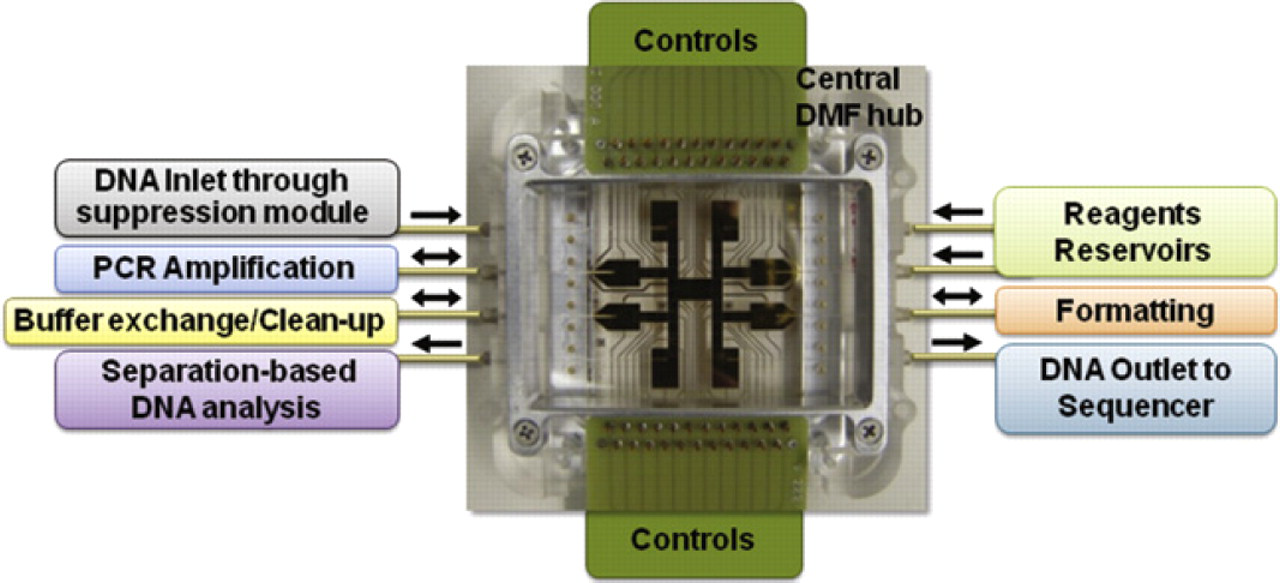
Illustration of a digital microfluidic platform functioning as a central hub. This configuration enables the integration of DNA sample processing modules, such as DNA suppression, PCR amplification, and DNA analysis, using a capillary interface. The interface can be also used to connect to external pumps, valves, and reservoirs for precise reagent dispensing as needed.
DMF is a technology in which discrete droplets (picoliter to microliter) are moved by a combination of electrostatic and dielectrophoretic forces on an electrode-patterned substrate with a hydrophobic coating, enabling basic liquid handling operations such as mixing, merging, and aliquoting. 12 Often, as in the examples below, droplets are manipulated while confined between two hydrophobic surfaces in a “closed-format” DMF configuration. As described elsewhere in greater detail, 13,14 the application of DC or AC voltage to an electrode pad near one side of a droplet causes a localized change in the droplet's contact angle (i.e., electrowetting), yielding a force imbalance that produces bulk motion of the droplet. 15 Although various benchtop biological assays and protocols have been adapted to the DMF format, 12,16,17 most published works have focused on executing all assay operations with droplets on a single DMF device, as in the example of DMF-based synchronized synthesis of peptide-based macrocycles. 18 For closed-format DMF devices, this paradigm typically requires that sample and reagent droplets are prepositioned inside the device before the lid is installed and the assay run, constraining available liquid volumes and limiting operational flexibility.
In contrast to previously published work, the DMF platform architecture described here uses the DMF electrode array primarily as a central hub, enabling liquid transfer to and from external fluidic elements and subsystems through a novel in-plane capillary interface. This interface provides a means to robustly interconvert liquid samples between continuous-flow, segmented-flow, and discretized droplet formats. Additionally, this interface allows multiple external connections to reagent reservoirs, eliminating constraints on reagent volumes available for use when repeated assay, washing, or sample preparation operations are required. Because droplets delivered to the DMF hub can be split, merged, and “parked” for extended periods of time, the capillary-interfaced DMF platform provides a flexible tool for scheduling, routing, and coordinating the transport of multiple samples between external processing modules that may have substantially different processing time or volume requirements.
To demonstrate the functionality offered by the capillary interface and the utility of the DMF platform architecture for NGS sample preparation workflow, we present two experiments addressing key DNA sample processing operations for sequence-based unknown pathogen identification. The first experiment demonstrates real-time monitoring and selective fraction collection from a continuous flow of sample delivered via capillary to the DMF hub. Specifically, conductivity monitoring enables closed-loop fraction selection and collection of eluting target analytes into discrete droplets. This functionality plays an important role in the automation of DNA processing protocols using an affinity based hydroxyapatite column by separating single stranded DNA from double stranded DNA. 19 The second experiment incorporates a DNA-binding magnetic bead assay to demonstrate buffer exchange, washing, and DNA concentration operations on the DMF platform. Buffer exchange or sample cleanup is the most repeated processing step in NGS library preparation workflow and may be performed as many as six times, typically after any enzyme-based assays such as ligation or PCR. Because they can be manipulated by magnetic rather than electric fields and reversibly bound to DNA, magnetic beads prove particularly useful in the context of a DMF device for concentration and washing operations. 17,20 Because buffer exchange requires a relatively large excess of washing fluid, the ability to dispense and remove this fluid on demand through the DMF capillary interface avoids the problem of limited capacity and the need for manual fluid replacement.
Experimental section
DMF Platform
As shown in Figure 2, the DMF platform consists of a custom-engineered polymer frame with opposed recesses accommodating the 50 × 75 × 0.7-mm patterned electrode array and ground plane substrates. Arrays of spring-loaded pogo pins provide electrical connections to contacts on both substrates. These substrates are fixed in the platform frame recesses by metal compression frames as shown in Figure 2 and are automatically registered relative to each other with a fixed vertical gap spacing of approximately 185 μm. This spacing enables the insertion of Teflon-coated fused-silica capillaries (Polymicro Technologies, Phoenix, AZ) with less than 170-μm outer diameter (OD) into the interstitial space between the DMF and the ground plane substrates as shown in Figure 3. Capillaries are passed through in-plane ports on the platform frame and swaged in place with CapTite capillary fittings (Sandia National Labs, Livermore, CA) as shown in Figure 2B. Before installation, capillary ends are cut with a precision fiber cleaver (CT-04B; Fujikura, Duncan, SC) to expose a uniform hydrophilic surface around the 50- or 100-μm inner diameter (ID) opening of the capillary. When connected to a syringe pump (PSD4; Hamilton, Reno, NV), these hydrophobically coated capillaries enable the clean transfer of microliter-sized droplets between the central DMF device and the external processing modules.
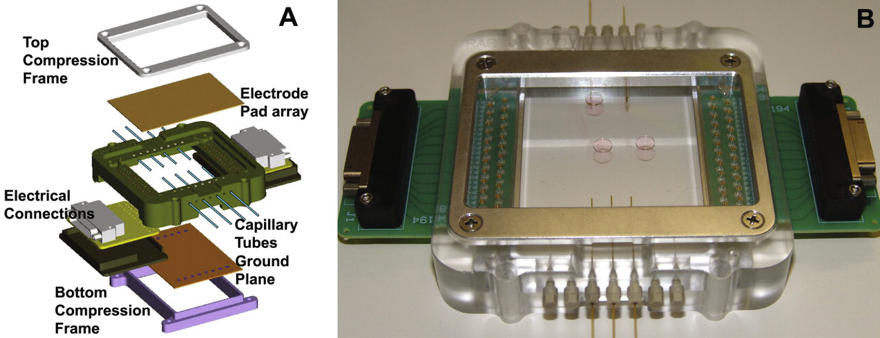
(A) Exploded view of the DMF platform assembly. Held in place by aluminum compression frames, the top and bottom DMF substrates self-register in the rectangular-shaped recesses of the platform frame, providing well-defined and highly consistent substrate-to-substrate spacing. (B) Image of an assembled DMF platform with confined droplets positioned on a transparent ITO electrode array. Capillary tubes fixed in position between the substrates by ferrules enable transport of fluid to and from the interior of the closed-format DMF device.
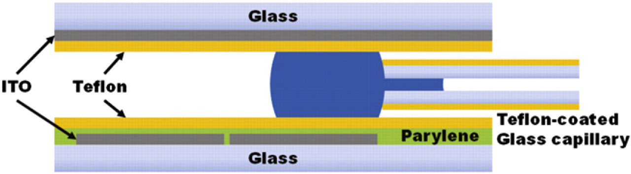
Schematic cross-section of the DMF platform with an in-plane Teflon-coated capillary in contact with a droplet confined between the lower electrode-patterned DMF substrate and upper ground plane lid. Capillary tubes inserted between the substrates have an OD slightly smaller than the substrate-to-substrate spacing of the DMF platform. The cleaved hydrophilic tip of the capillary is positioned relative to the interfacing electrode pad to optimize for either dispensing or aspiration.
DMF devices are fabricated using a protocol adapted from Jebrail et al. 21 Using our in-house microfabrication facilities, electrode and contact pad arrays are created by HCl-etching of the indium tin oxide (ITO) layer on a 50 × 75-mm ITO-coated glass slide (CG-41IN; Delta Technologies, Stillwater, MN) using a lithographically defined pattern. The electrode pads are then coated with a 2- to 4-μm-thick layer of Parylene C dielectric material (Specialty Coating Systems, Indianapolis, IN). To enhance surface hydrophobicity, a 1 wt% solution of Teflon AF dissolved in Fluorinert FC-40 (Fluka Analytical, St. Louis, MO) is spin coated onto the dielectric and baked at 160 °C for 10 min. Similarly, ground plane substrates are fabricated by directly spin coating Teflon onto the ITO surface of a substrate without first depositing parylene.
A custom computer-controlled electronic interface is used to activate individual electrodes by either manual keystrokes or script-based automated sequences. Droplets are actuated by applying AC voltage pulses (typically ∼50–105 V rms at 15 kHz) to a destination electrode, whereas neighboring electrodes are grounded. Droplet actuation is monitored using an MVX10 microscope (Olympus, Center Valley, PA) with a high-speed QIClick digital camera (QImaging, Surrey, Canada) yielding a field of view of approximately 35 × 26 mm. The microscope is equipped with fluorescence, dark field, and bright field imaging capabilities. Video frames are captured during experiments using Streampix 5 (Norpix, Montreal, Canada). Alternately, a custom video microscopy system with a zoom lens (NT58-240; Edmund Optics, Barrington, NJ) and CCD camera (4922-2010; Cohu electronics, San Diego, CA) is used with the Pinnacle Studio (Pinnacle systems, Mountain View, CA) video capture system. Images are analyzed using ImageJ (NIH, Bethesda, MD) to obtain droplet sizes for volume calculations and average fluorescence intensities.
Fraction Collection and Sorting
Figure 4 illustrates schematically a proof-of-concept experiment designed to explore closed-loop automation of the kind of fraction collection functionality required after hydroxyapatite separation. A syringe pump connected to the capillary interface continuously dispenses a “background” buffer solution (10 mM Na3PO4 with 0.005% w/v sodium dodecyl sulfate [SDS]) at 15 μL/min onto the DMF platform through a 150/100-μm (OD/ID) Teflon-coated capillary. Between the pump and DMF interface, an HPLC-style six-port injection/switching valve (Valco EHMA, Houston, TX) with a 5-μL holding loop allows the introduction of a “sample” bolus of high ionic strength (160 mM Na3PO4 buffer with 0.005% w/v SDS) containing fluorescein dye into the background buffer stream. The conductivity of the flow delivered through the capillary to the DMF device is monitored by a contactless flow-through conductivity detector (C4D; eDAQ, Denistone, Australia) sampling at 20 Hz and pretuned to maximize output signal amplitude for the sodium phosphate buffer with a probe voltage of 70 V at a frequency of 1100 kHz. The conductivity detector is positioned adjacent to the DMF platform with approximately 9 cm of capillary length between the detector and the outlet tip of the transfer capillary delivering buffer and sample. On the DMF device, the tip is positioned approximately 250 μm away from the edge of the receiving 2.5 × 2.5-mm DMF electrode pad. A second capillary connected to a vacuum line provides a means for pulling “waste” droplets off the DMF device.
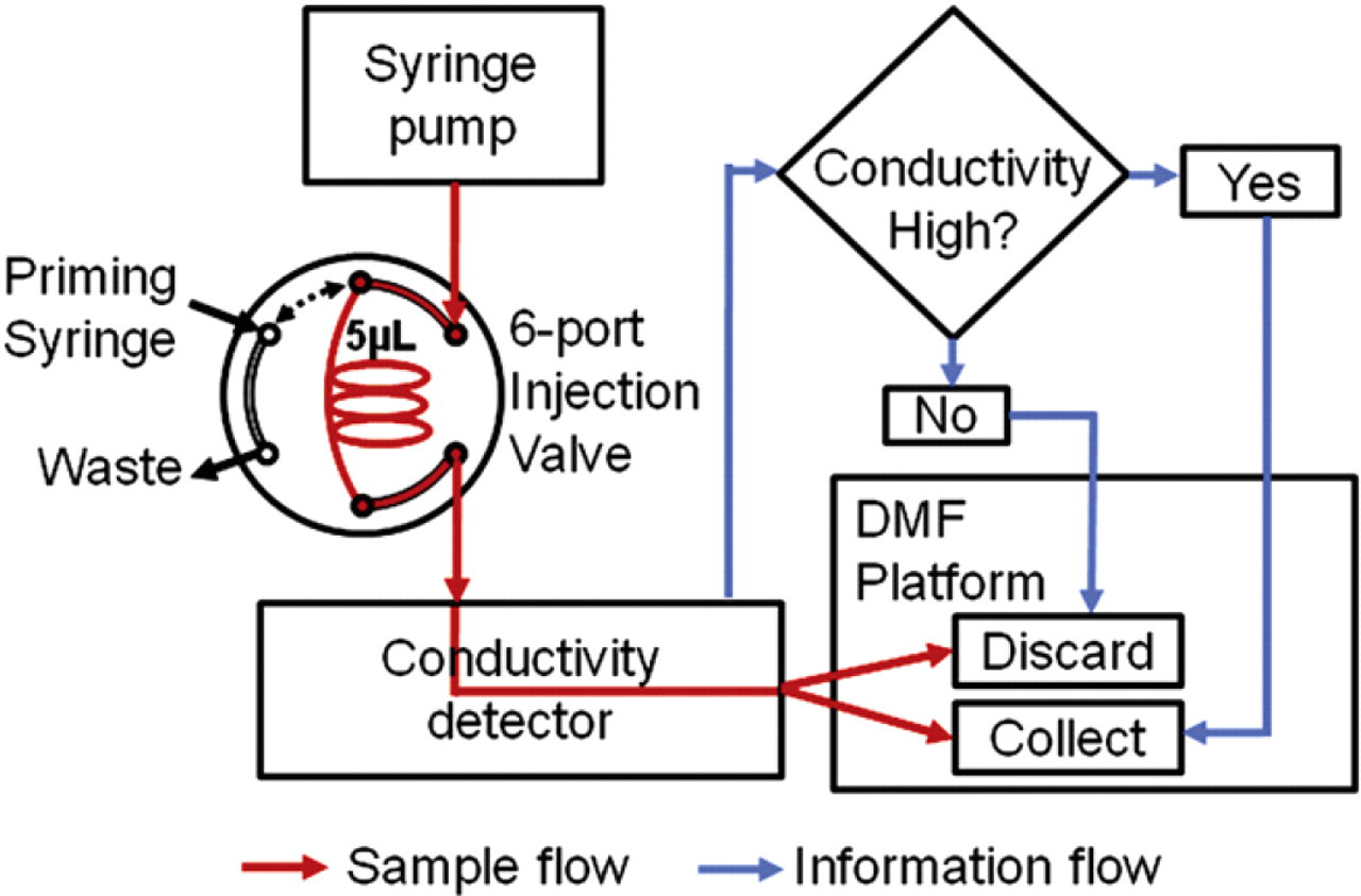
Process flow diagram for automated conductivity-based fraction sorting and collection. The control software monitors the conductivity of the incoming sample stream and compares it with a preset threshold value. When droplets corresponding to sample conductivity measurements above the threshold reach the DMF device through the capillary interface, the software automatically triggers DMF actuation to collect the high-conductivity fractions. Droplets corresponding to subthreshold portions of the sample stream are automatically moved to the waste capillary for disposal.
Custom control software implemented with Labview 10 (National Instruments, Austin, TX) is used to collect digitized conductivity measurements and trigger automated synchronous droplet actuation on the DMF platform to accomplish fraction sorting and collection as illustrated in Figure 4. At the typical 15-μL/min flow rate, sample liquids take approximately 2.8 s to transit the ∼9-cm length of capillary, and droplets forming on the DMF-end of the capillary reach an actuation-ready size of about 2.25 μL approximately every 9 s. Accounting for both this droplet discretization interval and the arrival time delay, the control software monitors the output of the conductivity detector and, when the measurement exceeds a threshold value, correlates one or more dispensed droplets with the high-conductivity flow segments. Droplets identified as containing high-conductivity sample are automatically moved to predetermined fraction collection locations and retained on the DMF device, whereas those lacking sample content are actuated into contact with the waste capillary for removal by vacuum.
Buffer Exchange and Washing
As a second proof-of-concept experiment exploring the benefits of a capillary-interfaced DMF hub for DNA sample preparation, magnetic DNA-binding beads are manipulated on the DMF platform to demonstrate an NGS-relevant buffer exchange. Buffer exchange experiments are conducted on the DMF platform using AMPure XP magnetic beads (Beckman Coulter Genomics, Danvers, MA) and fluorescently labeled DNA. A slightly higher DNA-to-bead solution volume ratio of 1:2 is used instead of the suggested 1:1.8 ratio. The TAMRA-labeled DNA ladder (Geneflo 625; CHIMERx, Milwaukee, WI) is first prepurified with AMPure XP beads to exclude the DNA ladder fragments below 100 base pairs, which are considered too small to be efficiently bound to the beads. The purified DNA is then eluted in 10 mM Na3PO4 buffer without any further dilution and used for all subsequent experiments. A typical assay begins by manually pipetting 16 μL of bead solution, DNA solution, and TE elution buffer onto three different reservoir pads of the DMF device as shown in Figure 5 A before installation of the ground plane lid. Washing buffer of either 70% or 95% ethanol is delivered through a 150/50-μm (OD/ID) Teflon-coated capillary by a manually operated syringe. A second Teflon-coated 170/100-μm (OD/ID) capillary connected to house vacuum via a collection trap is positioned at one of the DMF reservoir pads to allow aspiration of waste generated during the assay.
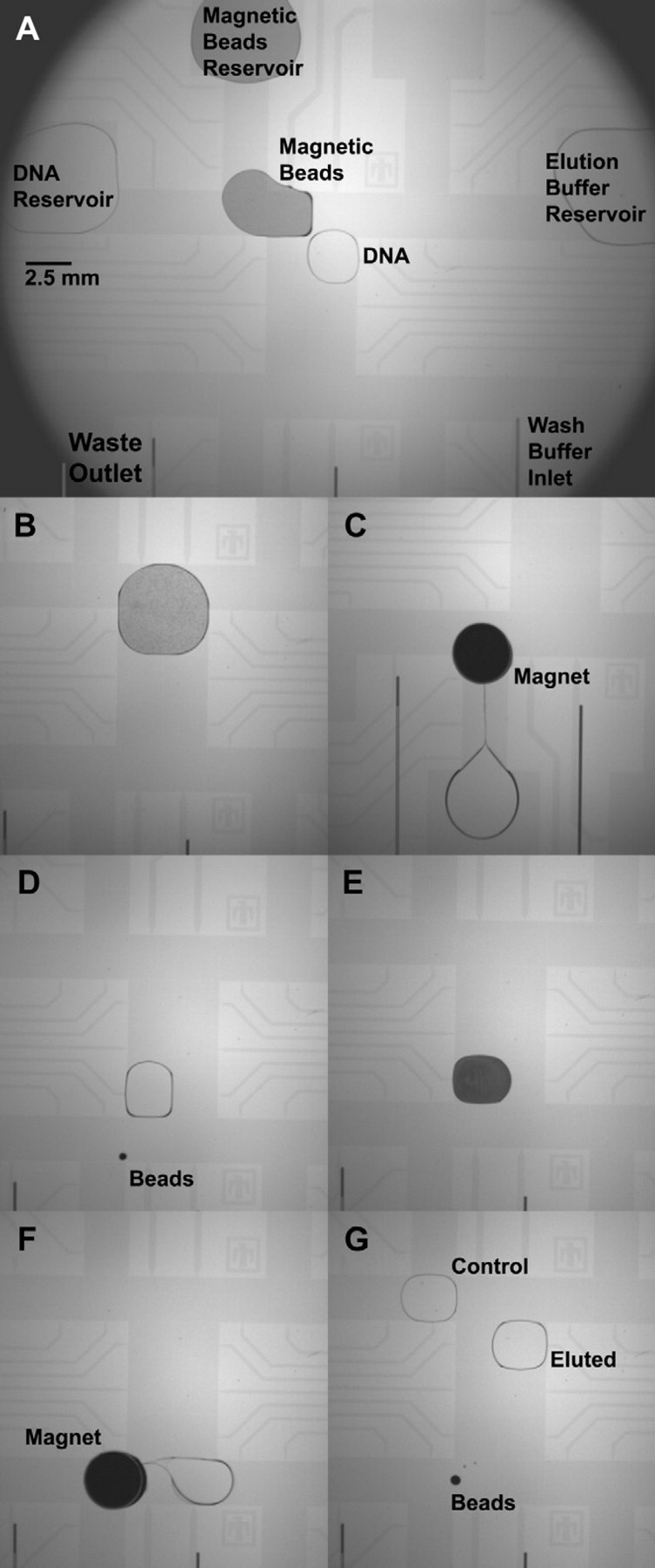
Video stills showing the buffer exchange assay performed on the DMF array using AMPure XP magnetic beads. Droplets of DNA and magnetic bead solution are split from their respective reservoirs (A), merged together, and actively mixed (B). Cylindrical magnets placed on the DMF hold the DNA-bound beads in place so that the supernatant can be removed (C) and the beads are thoroughly washed with ethanol (not shown). A droplet of elution buffer is introduced (D) and mixed with the beads (E) to unbind the DNA from the beads, which are then magnetically separated from the eluted sample (F). The separated beads, the eluted DNA droplet, and a reference control DNA droplet are then imaged for fluorescence analysis (G).
Magnetic beads are localized and held in place during the assay by positioning two 3.2 × 3.2-mm axially magnetized cylindrical NdFeB magnets (K&J Magnetics, Jamison, PA) above and below the bead-containing droplet. The lower magnet is held in position by its attraction to the magnet resting on the upper substrate, and both are positioned simultaneously by manually moving the upper magnet with tweezers. Once the magnets are in position, beads are focused into a pellet by the magnetic field, and the liquid can be separated from the beads by actuating the droplet away leaving the beads behind. New droplets can be moved into position to accomplish washing and buffer exchange operations, and removal of the magnets allows the beads to be resuspended in a new droplet medium. The buffer exchange assay with magnetic beads on the DMF platform takes 15–20 min to execute, which is comparable to the benchtop process.
Results and Discussion
Capillary-to-DMF Dispensing
The sequence of images in Figure 6 shows the precise dispensing and droplet formation of a single 10 mM Na3PO4 buffer droplet from a Teflon-coated capillary onto the DMF platform. As liquid is pumped through the capillary, a spherical droplet grows from the capillary end, eventually bridging the upper and lower substrates, overlapping the electrode, and growing to a size at which it can be actuated away by the electrodes as shown in Figure 6A–C. While the cleaved tip of the capillary tube provides a hydrophilic annular surface on which the dispensed droplet can grow, the Teflon coating of the capillary and substrates prevents liquid from wicking backwards along the capillary as the droplet forms. Once the droplet reaches a threshold volume of approximately 2 μL, a 300-ms voltage pulse is applied to the receiving electrode pad to overcome the capillary-face surface tension and separate the droplet from the capillary as shown in Figure 6C and D. Now centered over the electrode (Fig. 6E), the droplet may be actuated to a different position on the DMF electrode array (Fig. 6F). DMF actuation forces can reproducibly separate droplets with high precision: the volume of seven droplets serially dispensed from a capillary with a 15-μL/min flow rate was determined to be 2.25 ± 0.02 μL by microscope image analysis. Similar performance and results have been obtained with a variety of additional aqueous buffers and reagents typically used in DNA sample preparation protocols, including 1 M NaCl solution and even 5% bleach.
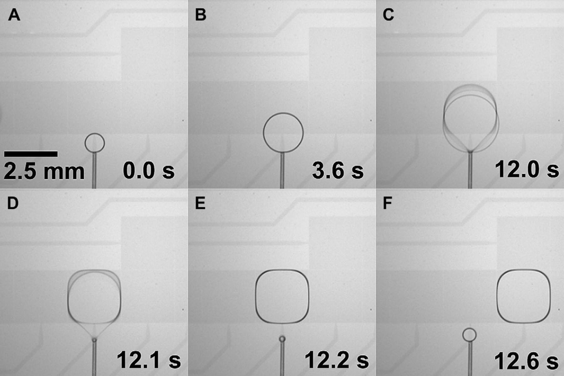
Sequence of video still images showing the delivery of 10 mM Na3PO4 buffer through an in-plane interface capillary to the DMF electrode array to form a movable droplet. The Teflon coating of the 170/100-μm OD/ID capillary prevents the liquid from wicking along the capillary during the continuous-flow dispensing process (A, B). When the dispensed droplet reaches the minimum size required for actuation, a voltage pulse is applied to the neighboring DMF electrode, separating the droplet from the capillary tip (C–E). The droplet may then be actuated normally on the DMF device (F).
As depicted in Figure 6A, the position of the capillary tip relative to the interfacing electrode pad can be optimized for either dispensing or aspiration. For dispensing, the preferred placement of the capillary tip approximately 250 μm short of the receiving electrode pad prevents cross-contamination by allowing standard-sized droplets to move normally across the receiving pad without touching the capillary. For fluid withdrawal from the DMF into a capillary, placing the capillary tip just inside the edge of the electrode pad allows the complete aspiration of the droplet and its contents into the capillary tube by vacuum suction or syringe draw. Figure 7 shows the aspiration of a 2-μL droplet containing fluorescein dye. Once the droplet is actuated onto the interfacing electrode pad, the hydrophilic tip of the capillary makes spontaneous contact with the droplet (Fig. 7B). The combined effect of the hydrophobic Teflon surfaces, the hydrophilic capillary tip, and the surface tension of the fluid, causes the droplet to remain intact, as it is completely aspirated into the capillary under negative (suction) pressure (Fig. 7C–F).
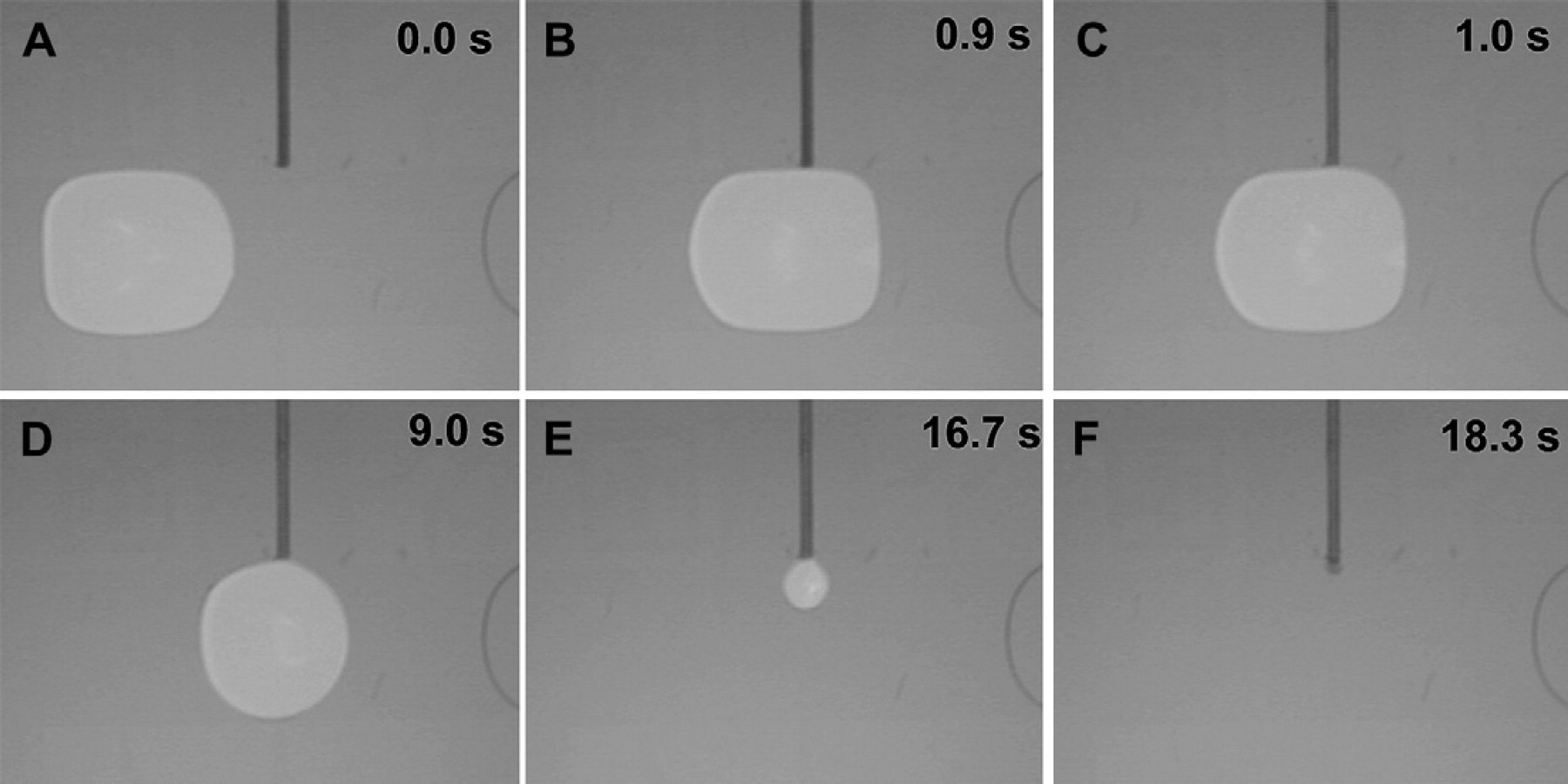
A 2-μL droplet of 10 mM Na3PO4 buffer with fluorescein is moved to the adjacent electrode pad (A) to be aspirated into a Teflon-coated capillary connected to a syringe pump. The droplet makes spontaneous contact with the hydrophilic tip of the capillary (B) and is pulled into the capillary as a continuous slug of liquid (C–E). A slight change in the capillary appearance is visible as the capillary fills with fluorescent fluid, but the lack of observable fluorescence on the capillary tip indicates complete aspiration of the droplet (F).
Fraction Collection and Sorting
Figure 8 shows video frames of the automated processing of 13 droplets on the DMF platform, observed under coilluminated dark field and fluorescence microscopy (Fig. 8C) with the corresponding conductivity measurement trace (Fig. 8A) and measured droplet fluorescence intensity (Fig. 8B). As the conductivity trace of Figure 8A shows, two 5-μL sample boluses were injected into the 15-μL/min background buffer flow at t = 32 and 97 s, respectively, through the dispensing capillary. Each injection event triggered the automated collection of four droplets with a total volume of 9 μL (droplets 2–5 and 9–12). Individual collected droplets were automatically routed in succession to predefined “parking spaces” on the DMF platform. Droplets that did not contain the eluted sample fraction (droplets 1, 6–8, and 13) were actuated to the waste pad and pulled off the platform using the vacuum as shown in Figure 8C (droplets 1 and 6–8). To illustrate the correlation between droplet content and sample injection time, Figure 8B shows the integrated fluorescence intensity of each dispensed droplet on the same time scale as the conductivity trace in Figure 8A. As expected, dispensed droplets containing only the background buffer showed no significant fluorescence. The lower fluorescence intensity of the initial (2 and 9) and final (5 and 12) droplets of each series of collected fractions results from the discrete drop-wise sampling of the dispensed flow. Because the injected sample bolus has a volume of 5 μL (plus some dispersion) and the droplets are each 2.25 μL, an individual droplet can only capture at most 45% of the sample peak. Polling the conductivity sensor at 20 Hz for a 15-μL/min flow, the estimated volumetric resolution of the conductivity-triggered sampling assuming minimal dispersion or dilution is approximately 12.5 nL.
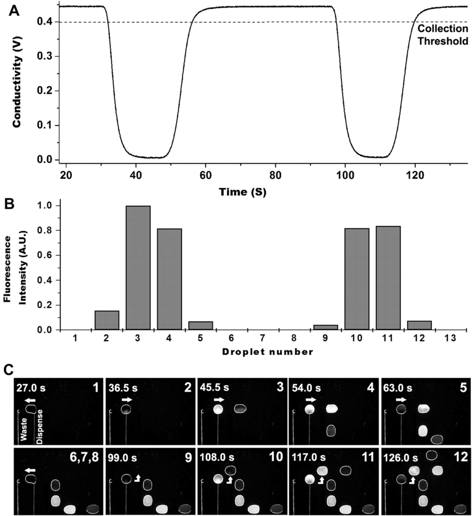
(A) Conductivity trace of the buffer flow entering the DMF platform through the capillary interface. (B) Integrated fluorescence intensity of the droplets (normalized to droplet 3) in the order they were dispensed. (C) Sequence of video frames showing the automated collection of the eluted fractions on the DMF platform. Each frame corresponds to the instant at which a droplet was separated from the dispensing capillary and is numbered according to the dispensing order. Droplets with fluorescence (2–5 and 9–12) were collected and moved serially to predetermined parking locations, whereas droplets with no fluorescence (1, 6–8, and 13) were removed from the device through a waste capillary connected to vacuum.
Although conductivity detection was used in this proof-of-concept experiment, the approach presented here can be readily adapted for use with other sensors as a generalized method for automating the transfer and subsampling of heterogeneous continuous or segmented flows onto droplet-based DMF devices. Fraction collection from a chromatography column is one potential application within the NGS DNA sample preparation workflow, which can benefit directly from a conductivity-based automation. Real-time conductivity monitoring can detect the distinct step changes in buffer concentration corresponding to the elution of single-stranded DNA from double-stranded DNA fractions from the hydroxyapatite separation column. The addition of an in-line UV absorbance detector operating in the same manner can further allow the identification and collection of droplets corresponding to DNA-rich fractions and the disposal of DNA-poor droplets, providing an effective method for concentrating the sample on the DMF platform.
Buffer Exchange and Washing
Figure 5 shows a series of video frames corresponding to the sequence of operations performed during a magnetic bead-based buffer exchange. First, a 2-μL droplet of fluorescently labeled DNA dissolved in 10 mM Na3PO4 buffer is split from the DNA reservoir and thoroughly mixed with a 4-μL droplet of magnetic bead solution also split from a reservoir as shown in Figure 5A and B. After a 10-min incubation period to allow binding of the DNA to the beads, a pair of magnets on opposite sides of the DMF device were positioned to localize the magnetic beads into a discrete pellet, and the supernatant droplet was moved to the waste capillary outlet and discarded (Fig. 5C). The magnets both above and below the DMF substrates were found to substantially focus the magnetic field acting on the beads, condensing the bead pellet and allowing for the near-complete separation of the supernatant droplet from the beads with minimal fluid carryover as shown in Figure 5D and G. The result was an estimated 100-fold reduction in volume from the original droplet to the isolated bead pellet. Earlier reports of magnetic bead assays performed on comparable DMF-in-air devices relied on electrowetting-based droplet splitting and magnets placed on only one side of the device, resulting in less effective bead/supernatant separations. 22,23
Not depicted in Figure 5 are two washing steps occurring between Figure 5C and D and performed with 5-μL ethanol droplets dispensed through the capillary seen in the lower right corner of Figure 5A. Each ethanol droplet was moved to the position of the bead pellet and actuated across the pellet to remove trace contaminants while the beads were held in place by the magnets. The ethanol wash buffer droplet was then actuated to the waste capillary and aspirated from the device by vacuum. These two washing steps yielded an estimated 10,000-fold dilution based on the relative volumes of the wash buffer droplets and bead pellet. After washing, a droplet of TE elution buffer was moved into position (Fig. 5D), and the beads were dispersed and resuspended in the elution droplet by active mixing (Fig. 5E). Finally, magnets were applied again to immobilize the beads, and the DNA-containing TE elution buffer droplet was separated from them (Fig. 5F) and positioned for fluorescence intensity analysis (Fig. 5G).
The DNA recovery efficiency of the buffer exchange experiment was estimated based on the relative difference of the integrated fluorescence intensity of control and eluted droplets after background subtraction. Of three independent runs, an average of 80% ± 4.8% recovery efficiency was obtained, comparable with the 70%–90% efficiency cited by the manufacturer for manual benchtop protocols. 24 Figure 9 A shows the fluorescence of an elution droplet with an 85% DNA recovery efficiency compared with a control droplet that was freshly split from the DNA reservoir. After careful fluorescence image analysis at each step in the DMF-based buffer exchange process, it appears that two factors account for most of the ∼20% DNA loss. First and most significantly, DNA that failed to bind to the beads during the initial incubation step is visible as the uniform but very weak background fluorescence of the supernatant droplet. Second and of lesser significance, some number of DNA-bound beads were evidently entrained in the supernatant droplet during the initial separation step, appearing as bright spots in Figure 9A. As further confirmation of these observations, the fluorescence image of the ethanol wash buffer, as seen in Figure 9B, shows no appreciable background fluorescence or bright spots, indicating that no significant amount of DNA or beads were lost in the washing steps. The measured recovery efficiency of 80% in this work can likely be improved by implementing a more rigorous mixing method 25 to promote increased binding efficiency between the beads and DNA.
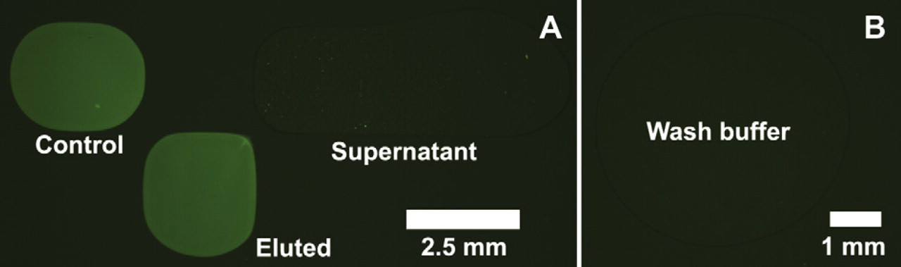
(A) Comparison of the fluorescence intensity of the eluted DNA droplet after buffer exchange, the control DNA droplet before buffer exchange, and the supernatant from the magnetic bead separation. Fluorescence observed in the supernatant droplet corresponds to unbound DNA and uncaptured beads. (B) Fluorescence image of the wash buffer collected after the washing step confirms that no DNA or beads are lost during this step.
Conclusions
We have taken the first steps in exploring a new approach to NGS sample preparation: a DNA processing system consisting of a central DMF hub interfaced through novel capillary interconnects to a number of external processing modules. Our preliminary efforts have demonstrated the flexibility and reproducibility with which fluids may be transferred to and from the DMF device through the in-plane capillary interface. Dispensed droplets with average volumes of 2.25 μL have been shown to vary less than 1% in size over multiple dispensing events. Proof-of-concept experiments have further demonstrated the benefits of the DMF platform and capillary interface for automatically selecting and archiving fractions from a continuous sample stream and for conducting buffer exchange and washing experiments with magnetic bead-bound DNA, both operations readily applicable to automating the DNA sample preparation workflows for NGS. Future work will incorporate additional library preparation processing steps by adapting external modules through the capillary interface to the DMF platform. In particular, we will build upon current efforts to interface microreactor chambers for enzymatic reactions, low-volume PCR for DNA amplification and electrophoretic gel separations for quantitative analysis.
Footnotes
Acknowledgments
We would like to thank Genevieve Pezzola, Marielle Remillard, and Eric Kittlaus for their contributions to the initial fabrication, characterization, and testing of our earliest DMF devices. Furthermore, we would like to acknowledge Jerry Inman and Dan Throckmorton for their engineering support and Stanley Langevin, Zachary Bent, and Steve Branda for their help with assay implementation. We would also like to thank Steve Shih and Prof. Aaron Wheeler, whose advice and assistance proved invaluable in the initial stages of our DMF development efforts. This work was funded through a Sandia Laboratory Directed Research and Development (LDRD) grant. Sandia is a multiprogram laboratory operated by Sandia Corporation, a Lockheed Martin Company, for the U.S. Department of Energy's National Nuclear Security Administration under contract DE-AC04-94Al85000.
Competing Interests Statement: The authors certify that they have no relevant financial interests in this manuscript and that any/all financial and materials support for this research and work are clearly identified in the manuscript.