
Abstract
Drug-testing technologies, biosensor fabrication, tissue engineering, and basic biological research depend strongly on the patterning of live animal cells. Current techniques for controlling cellular adhesion are restricted with two primary limitations. Firstly, the complexity of the available patterns is very limited and, secondly, the pallet of materials that induce cellular patterning is exhaustible. Here, we demonstrate a method for computer-aided control of cell patterning using a scientific inkjet printer that yields a highly complex cellular pattern suitable for applications in regenerative medicine and rapid prototyping, and a strategy for using in situ polymerization for fabrication polymeric patterns directly on-chip.
Keywords
Introduction
Cell patterning on a two-dimensional (2D) surface or within three-dimensional (3D) scaffolds has been broadly applied within the research community, 1 for example in the manipulation of cells in vitro in an attempt to understand cellular responses to the environment 2 or to pave the way for tissue engineering applications. As such, the technology has attracted much attention 3 and has been used in many ways, for example in engineered rat kidney tissue for implantation, 4 skin repair and regeneration, 5 and bone marrow stem cells for liver regeneration. 6 In addition, in 2007 human neural stem cells were implanted into the brain of a monkey with induced Parkinson's disease and it was demonstrated that damaged neurons indicative of the condition could be repaired. 7
General research on cell patterning is focused on understanding cell–biomaterial interactions in an attempt to understand and influence cell behavior on binding to a substrate. 8 –12 For example, both dendritic cell behavior 13 –16 and epithelial cell migration have been shown to be influenced and controlled by substrate rigidity, 17 and synthetic polymers have been used to modulate stem-cell differentiation. 14,18 Furthermore, Rosenthal et al. demonstrated that cell—cell signaling could be controlled by depositing cells in micro-wells of set sizes with varying distances between them and led to a better understanding of the role a substrate may play in mouse embryonic stem (mES) cell colony formation. 19
Current techniques for cell patterning follow two main strategies: the first embraces a modified office-based inkjet printer system to pattern living cells directly onto a substrate (with or without gelation materials) to form 2D- or 3D-patterned cells 20,22 –26 and the second is based on pre-patterning biomaterials followed by cell adhesion exclusively to designated domains. 27
The second strategy has attracted much attention and includes a number of techniques. One example of this approach is the use of soft lithography, with soft elastomeric stamps (in polydimethylsiloxane) used to transfer cell-binding materials onto a substrate in a highly defined pattern. 28 –30 Another example is photolithography (ultraviolet (UV) radiation—initiated polymerization through highly defined masks). 31 Aerosol-based polymer deposition processes have also been applied and the advantages of this approach are an increase in resolution (to 25 μm) and it can additionally be applied to curved surfaces. 32 More exotic approaches include techniques such as dip-pen nanolithography, 33,34 which relies on atomic force microscopy to deliver cell-binding materials to highly defined, specific positions on a surface. This naturally provides a tremendous resolution but also has a number of limitations with respect to applicability, scale-up, and general accessibility.
In the research presented here, a new way of controlling scientific inkjet printing is presented to allow for the fabrication of easily scalable, flexible, and highly complex cellular patterns suitable for applications in regenerative medicine and rapid prototyping. Moreover, we present a strategy for using in situ polymerization for the fabrication of polymeric patterns directly on-chip, which provides a simple, user-friendly, and flexible method for cellular patterning and is an attractive alternative to extensive (sometimes unachievable) optimizations of patterning conditions for presynthesized polymers.
Materials and Methods
Materials
All materials were purchased from Sigma—Aldrich (Gillingham, Dorset, UK) unless otherwise stated. mES (mES-Oct4) cells were provided by Josh Brickman from the Institute for Stem Cell Research, University of Edinburgh.
Polymer Patterning by In Situ Polymerization
Clock shape patterns were fabricated by printing monomers, divinylbenzene (DVB) solution or 2-(methylthio)ethyl methacrylate (MTEMA) solution (all 50% w/w in DMSO) mixed with the initiator azobisisobutyronitrile (0.1% w/v in monomer solution) onto agarose-coated slides covered with a thin layer of paraffin oil (150 μm depth). The monomer solution droplets sank and settled on the agarose layer due to the high densities of the monomer solutions compared with oil. The oil layer prevented the evaporation of the monomers from the printed slides during the 15-h incubation in an oven at 60 °C to afford polymerization in situ. Removal of the oil layer was easily achieved by washing with water and ethanol, respectively. The polymeric pattern was obtained by printing five drops of monomer per spot which generated spots of 200 μm in diameter after polymerization.
Preparation of the Coated Glass Slides
1.0% w/v of agarose (Type I-B) was dissolved in deionized water at 100 °C and aminoalkylsilane glass slides were dip-coated with this solution at 65 °C. The coated slides were dried in open air for 24 h before use. The thickness of the dried agarose coating was 2.3 μm (as measured by SEM). Thicker agarose coatings of 9.3 and 26.0 μm thickness were obtained by spreading 1 and 2.5 mL of 1% agarose solutions onto the glass slides, respectively.
Collagen Patterning
The collagen patterns were fabricated using an inkjet printer (Microdrop, GmbH, Norderstedt, Germany) equipped with a micro-pipette (AD-K-501, 70 μm diameter nozzle, Microdrop Technologies GmbH, Muehlenweg, Norderstedt, Germany). The typical printing parameters were: 140 V voltage, 29 μs pulse and 100 Hz frequency. A solution of 0.1% w/v collagen in 0.1 M aqueous acetic acid was prepared and used as ink for the printer. The collagen pattern was obtained by printing two drops per spot in a cyclic mode, which generated spots of 200 μm in diameter.
Cell Culture
HeLa cells were used at passage 10, while mES-Oct4 cells were used at passage 8. The cells were seeded at a density of 7 × 10 5 per slide and incubated in a HERAcell 150 incubator (Thermo Fisher Scientific, Inc., Waltman, MA) at 37 °C under 5% CO2 with 7 mL media per slide in a four-well plate with rectangular dimensions (Nunc, Denmark). The media for HeLa cells was RPMI 1640 complemented with heat inactivated fetal calf serum (10% v/v), penicillin (100 units/mL), streptomycin (100 mg/mL) and l-glutamine (4 mM). The media for mES-Oct4 cells was Glasgow Minimum Essential Medium complemented with heat-inactivated fetal calf serum (10% v/v), penicillin (100 units/mL), streptomycin (100 mg/mL), l-glutamine (2.0 mM), sodium pyruvate (2.0 mM), 2-mercaptoethanol (0.1 mM), and leukemia inhibitory factor (0.18 units/mL). Cells attached to the slides were stained with a nuclei dye (Hoechst 33342, Sigma-Aldrich, Gilingham, Dorset, UK) for 15 min and fixed with formaldehyde solution (4% w/v) in phosphate-buffered saline (pH 7.5) for 15 min.
Results and Discussion
The scientific inkjet printer operated in a “drop-on-demand” mode via a piezoelectric firing mechanism, which created droplets of a volume of approximately 380 pL at frequencies adjustable in the range of 0–2 kHz. A stroboscopic camera was used to monitor droplet formation and this allowed accurate control over the volume of the deposited materials by simply varying the number of drops printed in any specific location. The advantages of this class of printer are that they can be set to print any desired pattern using virtually any material and addressed to any specific position on a slide. Recently, this inkjet-based approach was used to prepare 231 formulations of three independent liquid crystals in a HT and highly miniaturized manner (in essence converting a conventional three component—phase diagram into a rectangular format). 35 In addition, it has been used in the preparation of 1800 polymers on a glass slide by in situ nanoliter polymerization. 36,37 Because the already published approaches toward in situ polymerizations were designed for generating large numbers of different polymers in a format suitable for HT cellular screening (microarrays and grids), the recent research has been focused on using in situ polymerization for cellular patterning and enabling an increase in the library of synthetic materials suitable for cell patterning.
In the process of printing, a desired image or picture was converted from a Microsoft Windows Bitmap file into a coordinate file by WinDig 2.5 software 38 and, subsequently, to a macro file using an in-house bitmap converter, which could be read by a Microdrop inkjet printer (for details see 39 ). This allowed the printer to apply different solutions and print them at the required positions with high accuracy (Scheme 1). Collagen was chosen as the patterning material because it is a well-known universal cell binder and is widely applied in cell cultures. 24 The quality of the printed patterns was controlled by the size of the printing nozzle and the viscosity of the solutions. Different concentrations of monomers and collagen solutions were tested, with the printer generating consistent drops when using monomer solutions of 50% w/w in DMSO and collagen solutions between 0.1 and 1 g/mL. The oil layer successfully prevented the evaporation of monomers from the printed slides during the 15-h incubation at 60 °C, which was essential to permit in situ polymerization. Subsequently, the oil layer was easily removed by washing with water and ethanol. Both collagen-and polymer-patterned slides were dried and sterilized under UV radiation for 30 min before use. HeLa cells 40 and mES-Oct4 cells 41 both adhered and proliferated specifically at the patterned areas of the slides. Cell adhesion is demonstrated in Figures 1–4, where the sharpness of the clock can be observed on staining of the cell nuclei. Figure 1B and C also show that the drops of the printed collagen are approximately 230 μm in diameter, which gives the limit of the patterning fidelity. The attached HeLa cells, which spread over all the poly(MTEMA), poly(DVB) (Fig. 3), and collagen (Fig. 1) substrates show a healthy cellular morphology. The clock image patterned with mES-Oct4 cells is shown in Figures 2A and 4A. Interestingly, mES-Oct4 cells (after 48-h incubation) began to develop 3D cellular aggregates on both polymer and collagen patterns, as shown by Figures 2B, C and 4B, C, with live cells.
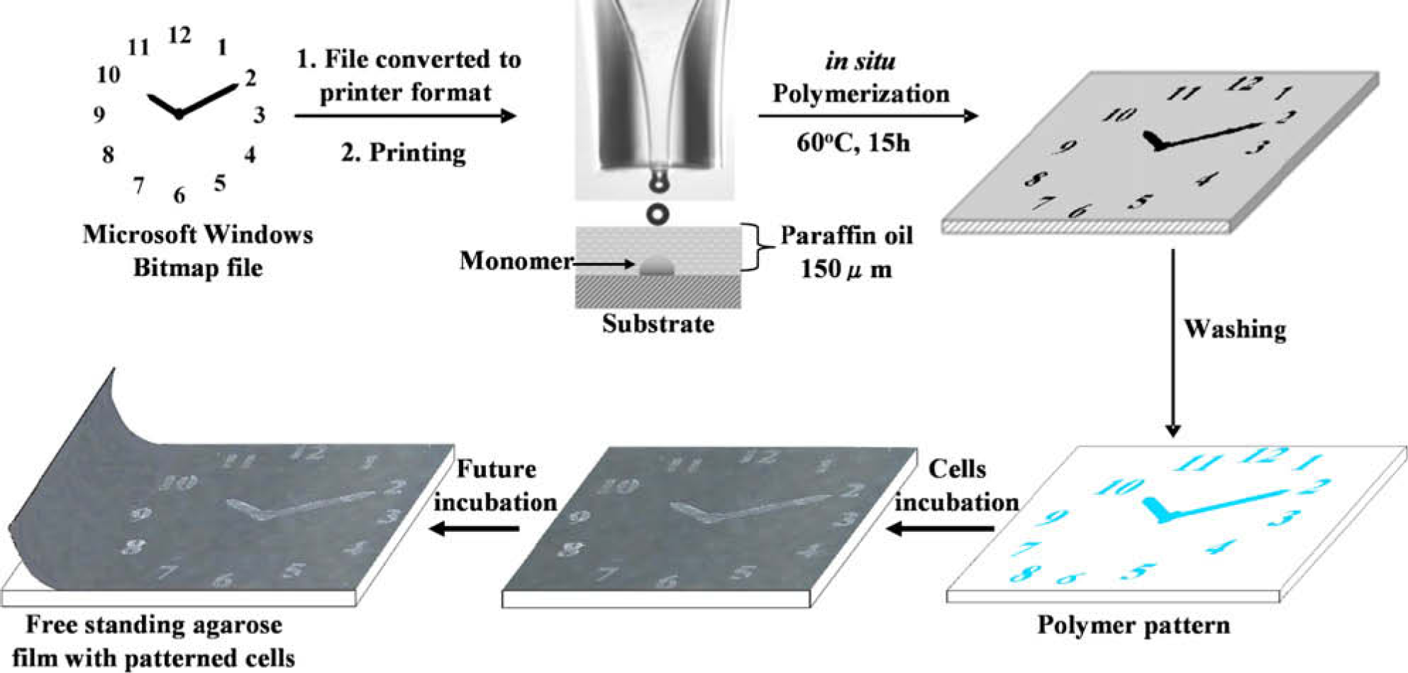
The generation of printer files for a clock pattern followed by patterning via in situ polymerization (collagen alternatively), cellular binding, and substrate detaching to obtain a free-standing film with patterned cells.
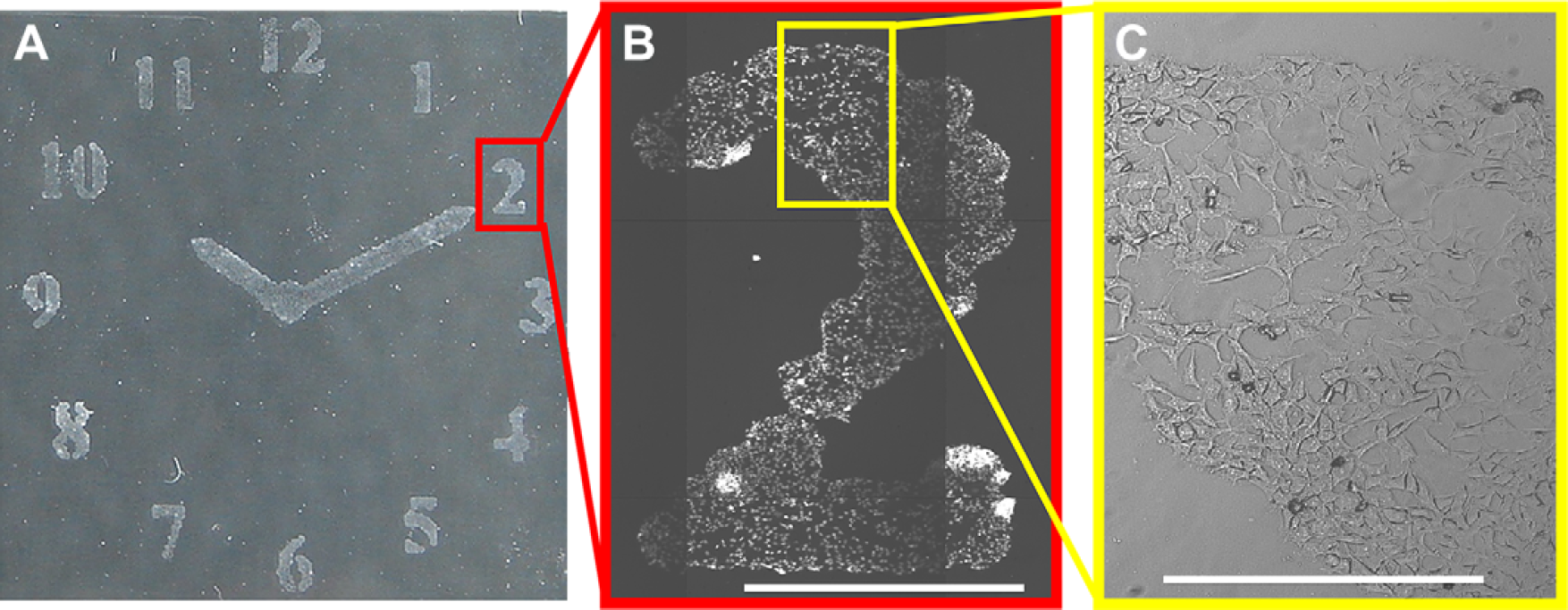
Cell patterning via inkjet printing: (A) HeLa cells patterned in a clock shape on collagen inkjet printed onto agarose (26 × 26 mm). (B) Hoechst 33342 (for nuclei staining) images of HeLa cells in a patterned “2” (scale bar 1 mm). Images were scanned using a Nikon microscope controlled by the Pathfinder software (Imstar, S.A., Paris, France) using a 10×/0.30 objective and a DAPI filter. (C) Bright light image expansion showing part of the number “2” (Scale bar 0.25 mm).
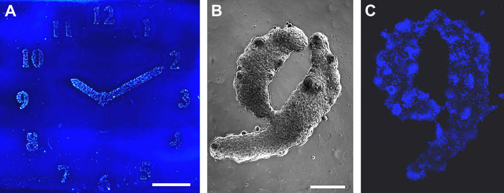
Patterned mES-Oct4 cells on: (A) collagen patterns printed on agarose-coated glass slides, fixed with formaldehyde (4% w/v) and stained with Hoechst 33342 (nuclei stain). The image (scale bar 5 mm) was taken with a BioAnalyzer 4F/4S equipped with a light scanner (LaVision BioTech GmbH, Bielefeld, Germany); (B) living mES-Oct4 cells patterned “9,” on collagen inkjet printed onto an agarose layer. Images were taken with a Leica microscope using a 5×/0.12 objective, before fixing and staining (scale bar 0.5 mm); (C) fixed and stained “9” with mES-Oct4 cells (scale bar 0.5 mm).
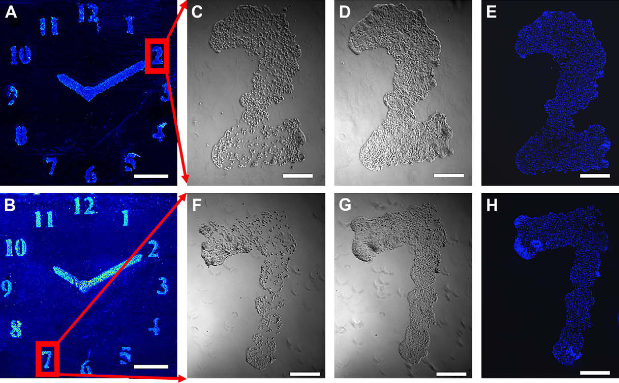
Patterned HeLa cells on polymeric patterns (A) poly(DVB); (B) poly(MTEMA), in situ polymerized via printing on agarose-coated glass slides, fixed with formaldehyde (4% w/v) and stained with Hoechst 33342 (nuclei stain). The image (26 × 26 mm) was taken with a BioAnalyzer 4F/4S equipped with a light scanner (LaVision BioTech GmbH, Bielefeld, Germany) (scale bars 0.5 cm). Living HeLa cells patterned “2” and “7,” on in situ prepared polymers by inkjet printing onto an agarose layer; (C) cells on poly(DVB) after 24-h incubation; (D) cells on poly(DVB) after 48-h incubation; (F) cells on poly(MTEMA) after 24-h incubation; (G) cells on poly(MTEMA) after 48-h incubation (scale bars 0.5 mm). Images were taken with a Leica microscope using a 5×/0.12 objective, before fixing and staining. Fixed and stained “2” and “7” with HeLa cells; (E) poly(DVB) after 48-h incubation; (H) poly(MTEMA) after 48-h incubation (scale bars 0.5 cm). Images were taken with a Leica microscope using a 5x/0.12 and DAPI filter.
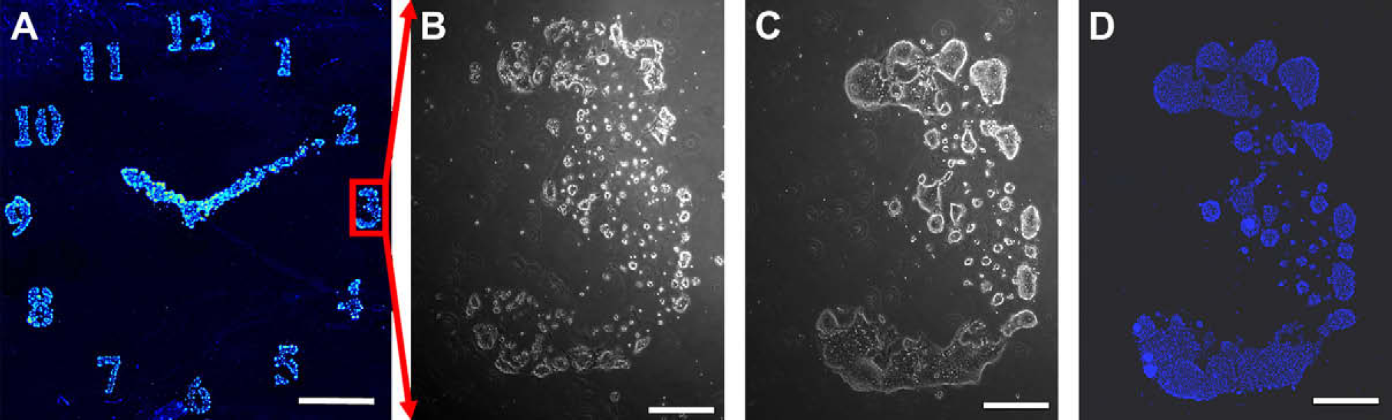
Patterned mES-Oct4 cells on (A) poly(DVB) patterns printed on agarose-coated glass slides, fixed with formaldehyde (4% w/v), and stained with Hoechst 33342 (nuclei stain). The image (26 × 26 mm) was taken with a BioAnalyzer 4F/4S equipped with a light scanner (LaVision BioTech GmbH, Bielefeld, Germany) (scale bars 0.5 cm); living mES-Oct4 cells patterned “3,” on in situ prepared polymers by inkjet printing onto an agarose layer; (B) cells on poly(DVB) after 24-h incubation; (C) cells on poly(DVB) after 48-h incubation, (scale bars 0.5 mm). Images were taken with a Leica microscope using a 5×/0.12 objective, before fixing and staining; (D) fixed and stained “3” with mES-Oct4 cells, images were taken with a Leica microscope using a 5x/0.12 and DAPI filter.
To further evaluate our method, we generated cellular gradients that showed a constant decrease in cellular attachment proportional to the amount of collagen printed. To print this collagen gradient, the initial collagen solution was diluted 50-fold (0.002% w/v collagen solution) and inkjet printed onto an agarose-coated slide in a one-drop-per-position mode. During the first sweep, 100 parallel lines (5 mm long) were printed with a 130 μm stop-gap between every two adjacent lines. In each subsequent printing, the number of printed lines was decreased by two sequentially. Because the distance between two drops was less than 230 μm, the printed collagen drops were seen to merge together generating a gradient on the agarose coating. On cell culture, the printed gradients showed a linear change in affinity for the cells (Fig. 5, the gradient of mES-Oct4 cells is shown in Fig. 6). These findings improve on those previously reported 24 and indicate that the precision of biomolecular deposition using this approach is vastly advanced.
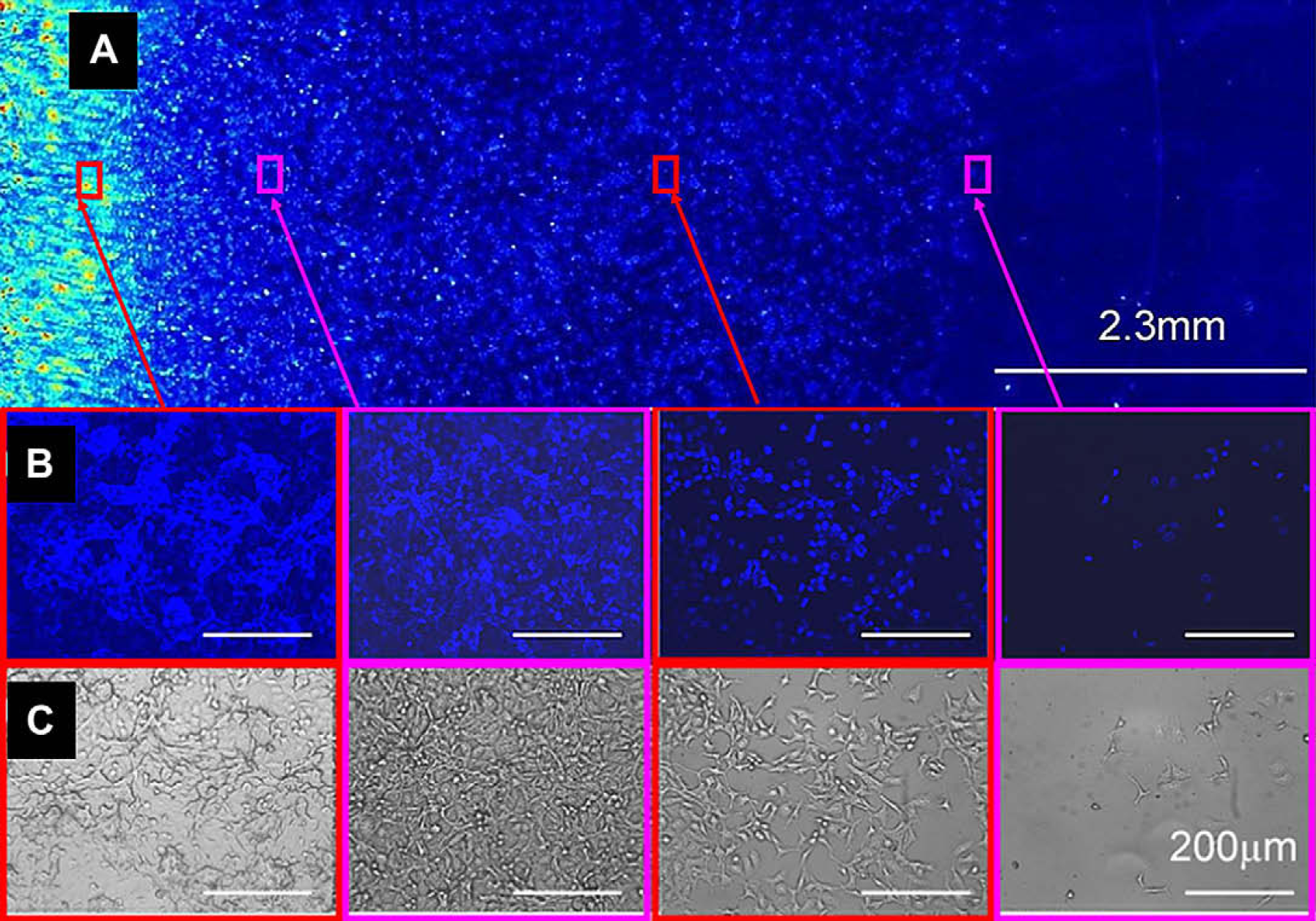
HeLa cells grown on a collagen gradient printed on an agarose-coated glass slide. The cells were stained (Hoechst 33342) and fixed. (A) Fluorescent images were taken with a BioAnalyzer 4F/4S equipped with a light scanner (LaVision BioTec GmbH, Bielefeld, Germany) with a DAPI filter; (B) fluorescent and (C) brightfield images of regions of the gradient array (images were obtained using a Nikon microscope controlled by the Pathfinder software [Imstar]) using a 10×/0.30 objective and a DAPI filter. The scale bars in the expanded images are 200 μm.
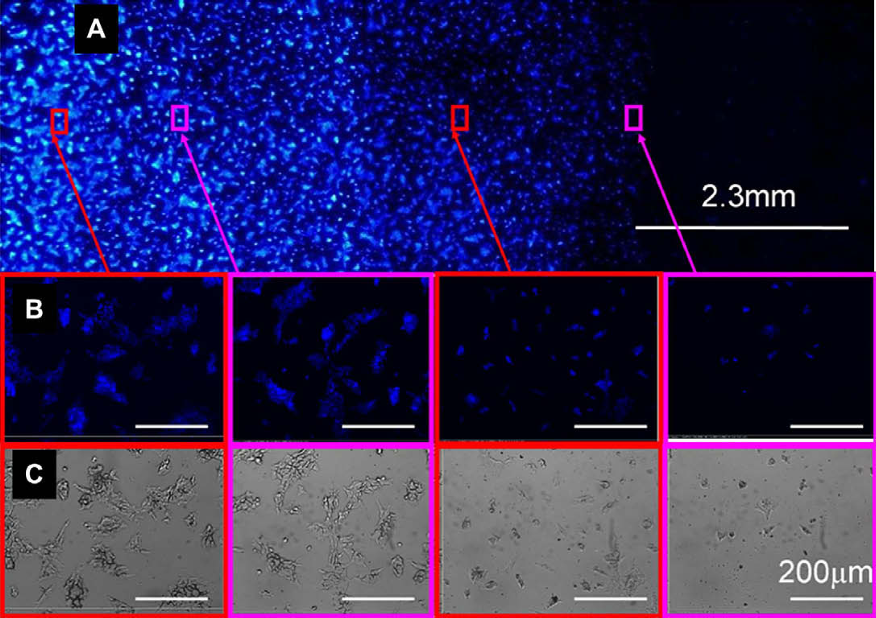
mES-Oct4 cells grown on a collagen gradient printed on an agarose-coated glass slide. The cells were stained (Hoechst 33342) and fixed. (A) Fluorescent images were taken using a CCD—based fluorescent Bioanalyser (LaVision Biotec) with a DAPI filter; (B) fluorescent and (C) brightfield images of regions of the gradient array (images were obtained using a Nikon microscope controlled by the Pathfinder software [Imstar]) using a 10×/0.30 objective and a DAPI filter. The scale bars in the expanded images are 200 μm.
Potential Application
As non-selective cellular transfer has been previously applied in regenerative medicine, most notably in the regeneration of damaged epithelium, 42 it was of interest to investigate this area of research using our cell-patterning technique. As such, we fabricated a free-standing film of patterned HeLa cells, whereby the agarose layer could be detached from the glass slide to give a hydrogel film impregnated with cells as shown in Figure 7. Agarose is well known to be a cytophobic material and has been applied extensively in cellular patterning and can effectively prevent the adhesion of most cell types. 14 As such, agarose presented itself as an ideal candidate on which to develop a free-standing cell-patterned hydrogel film. Slides with varying thicknesses of dried agarose films (2.34, 9.34, and 26 μm, as measured by SEM) were evaluated. It was immediately observed that the thinner agarose films firmly adhered to the amino-glass slides (>2-week incubation), whereas 9.34 and 26 μm agarose films detached after as little as 24 h. Figure 7A shows a free-standing agarose film (thickness: 26 μm) patterned with HeLa cells (nuclei are stained and the cells are fixed), which became visible after the agarose film was dried (Fig. 7B).
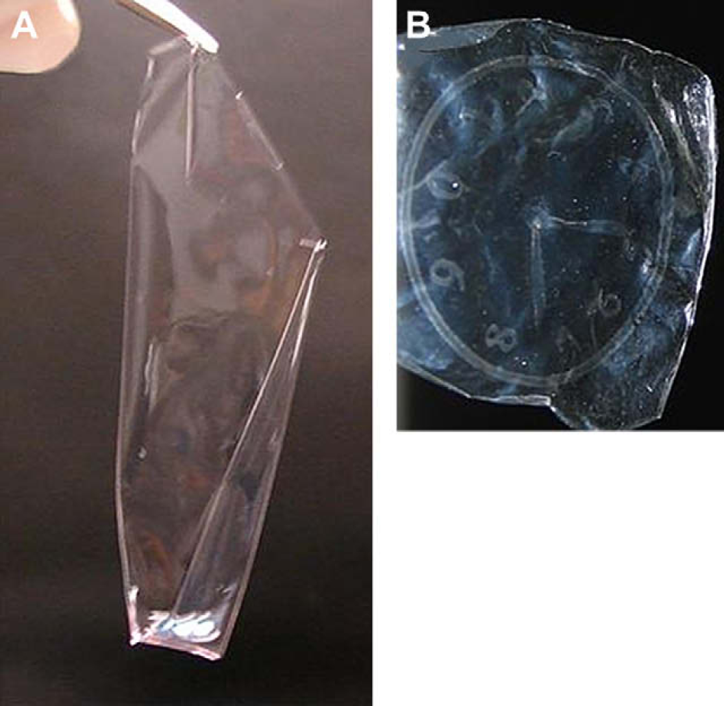
(A) A wet, free-standing agarose film (34.4 μm) with patterned HeLa cells (approximately 26 × 26 mm); (B) The cell-patterned clock becoming visible after the agarose film was dried (26 × 26 mm).
Comparisons with Other Cellular Patterning Methods
The general disadvantages of photolithography-based patterning methods, such us micro-contact printing using a mold (microfabricated via photolithography) 43,44 and photopatterning using a mask 21,45 –49 are the high costs of the process, reagent availability, and the complexity of the procedure that does not allow a high flexibility with regard to patterning. 32
In contrast, the method presented here allows rapid prototyping of cellular patterns depending only on the generated Microsoft Windows Bitmap file and enables a practically infinitive variety of patterning materials as they can be derived from different kinds of monomers and the combinations of them. Other attempts, apart from photolithography, include inkjet- and aerosol-based direct deposition of animal cells, 20,22,50,51 laser-guided direct writing (Odde and Renn, 2000) 51 and the direct spraying of polymers. 32 Inkjet-and aerosol-based cell deposition require encapsulation of living cells in droplets. However, the droplet formation limits the viability of the deposited cells, although the methods do allow high cell deposition of up to 1000 cells/s. This is significant in comparison to “laser-guided direct writing,” which is based on the utilization of optical forces as “tweezers” for guiding the cells one after another (i.e., one cell can be deposited per second). In addition, these strategies suffer from the same disadvantage of the difficult migration control of deposited cells. In contrast, in the method presented here, cell attachment is restricted to cytophilic regions of the patterned surface and the viability of the patterned cells is self-controlled as dying cells detach from the patterns and can be removed through gentle washing.
Spraying of polymers is an elegant patented method that allows patterning of polymers with resolution down to 25 μm either on planar or curved surfaces. However, the method does suffer from limitations, including polymer solubility and resistance to high temperatures (as it must be deposited through an aerosol). On the contrary, here we present on-chip in situ polymerization that enables pattern fabrication containing even highly cross-linked (non-soluble) polymers (such as poly(DVB)) and, as such, the method is not restricted to the thermostability or the solubility of the polymers yielding an increase in the possible diversity of the approach.
Resolution is an important factor for evaluating cellular patterning. According to Silva et al., 32 the lowest inkjet-generated dot diameter is restricted to 350 μm, whereas in this article we successfully demonstrated a patterning with a resolution of approximately 250 μm. However, this restriction in resolution is a technical matter rather than a methodological limitation. Recently, Osch et al published work in which the pattern width was reduced below 50 μm. 52
Special attention must additionally be drawn to the differences between the direct patterning of biomolecules using an inkjet printer 24 and the method reported here.
First of all, the advantage of the presented approach is the combination of the benefits from widely available computer softwares and the precision and flexibility of scientific inkjet printers. We took the first and important step from simple figures (such as lines 24 and triangles 53 ) toward complex patterns that can be applied to print naturally occurring cellular patterns, such as tissues or organs. Furthermore, by our replacement of biomaterials that are normally used for printing, such as collagen and fibrinogen, by synthetic polymers, we reduced the risk of microbiological contamination of patterned cells. This issue is of specific and vital importance in consideration of regenerative medicine applications.
Footnotes
Acknowledgments
The authors thank Ilika Technologies and the EPSRC for funding and Dr Andy Turner for generating the bitmap converter and Lois Alexander and Anne Klara Hansen for expertise.
Competing interests statement: The authors declare no competing interests.