
Abstract
We have developed a general strategy for the addition of high-throughput colony picking capability to most standard liquid-handling robotic platform. This strategy is easily implemented and requires minimal capital outlay (less than $2500.00). To illustrate this strategy, we describe the modification of a Caliper Life Sciences Sciclone ALH (Automated Liquid Handler) 3000 together with a general calibration methodology that can be applied to most liquid-handling robot capable of X, Y, Z positioning.
This project has been funded in whole or in part with federal funds from the National Cancer Institute, National Institutes of Health, under contract N01-CO-12400. The content of this publication does not necessarily reflect the views or policies of the Department of Health and Human Services, nor does mention of trade names, commercial products, or organizations imply endorsement by the U.S. Government.
Introduction
Laboratory automation has revolutionized biological research and has emerged as a major enabling factor in modern genomics and proteomics facilities. Robotic platforms allow for cost-effective and precise high-throughput operations. However, they also carry significant burdens in terms of their initial cost and footprint. In our laboratory, we purposefully select automation platforms that are capable of supporting multiple functions or capabilities, in an effort to minimize the impact of these drawbacks. In keeping with this philosophy, we have developed a generalized strategy for the addition of high-throughput colony picking capability to most standard liquid-handling robotic platforms. To illustrate this concept, we describe modification of a Sciclone ALH (Automated Liquid Handler) 3000 (Caliper Life Sciences, Hopkinton, MA). As described, these modifications require minimal capital outlay (less than $2500.00) and can be adapted to most any liquid-handling robot capable of X, Y, Z positioning.
Hardware
The Sciclone ALH 3000 was chosen for the initial adaptation of this application because of its ±20 μm specification for X, Y, Z position repeatability. Another attractive feature of the Sciclone is its ability to go to any X, Y, and Z location via associated GUI software, eliminating the need for scripting and, as such, making method development easier.
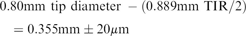
The ±20 μm repeatability is measured at the drive mechanism and therefore, cannot be transferred to accuracy at the tip of the Z-8 pipettor that will be used for picking. The Z-8 is a set of eight probes on the ALH 3000 that can raise, lower, aspirate, and dispense individually and have a fixed 9 mm spacing. Before attempting to convert any liquid handler into a colony picker, it first must be determined if the instrument can place its probes with sufficient precision to discriminate between colonies. The 50-μL tips that load onto the Z-8 have a total indicator runout (TIR) specification of 0.889 mm. This TIR will add to the error in positioning the tip on the X and Y axes. The 50-μL tip has a measured diameter at the tip end of 0.80 mm, but because of the runout, only 0.355 mm of the tip diameter can be expected to hit the same X, Y spot repeatedly from tip to tip ± the 20 μm repeatability error from the drive system.
According to these calculations, a Z-8 tip should be able to hit an X, Y value repeatedly with a tip diameter of 0.355 mm. To test these calculations, we wrote a quick method that repetitively loaded a new tip and went to a fixed X, Y location and placed a small hole in some clay on the deck with the instrument approaching the spot from different directions. After 12 repetitions, the clay was inspected and the hole diameter was compared with the tip diameter. The diameter of the hole was determined to be 1.35 mm. This confirmed the calculation above. The 12 repeated approaches had an accumulated TIR of 0.55 mm. This empirical TIR includes tip error and any errors in the mechanical drive system. Such a method is a good empirical test of the suitability of any robotic system being considered for a colony picker retrofit.
Figure 1 illustrates a rearview of the gantry on the Sciclone ALH 3000. The (A) points to the CCD camera that is mounted on the gantry. The camera used is a Pulinex model TM-6CN (Pulinex America, Inc., Sunnyvale, CA) salvaged from an obsolete piece of equipment. The camera produces an 8-bit gray scale image that is transferred to the computer via a USB Video frame grabber (Zarbeco, Inc, Randolph, NJ). The gantry positions the camera in both X and Y directions. The Z location is fixed because the bracket is mounted to the top of the gantry and therefore cannot move in the Z direction. The mounting bracket is constructed out of 1.5-in. square aluminum tubing and the camera is set at a height such that the field of view can cover an SBS single well plate (Nunc 140156, Nalge Nunc International, Rochester NY) in six images (Fig. 4). The camera captures an image of 640 × 480 pixels. The images are cropped by the software to an image size of 430 × 444 pixels.
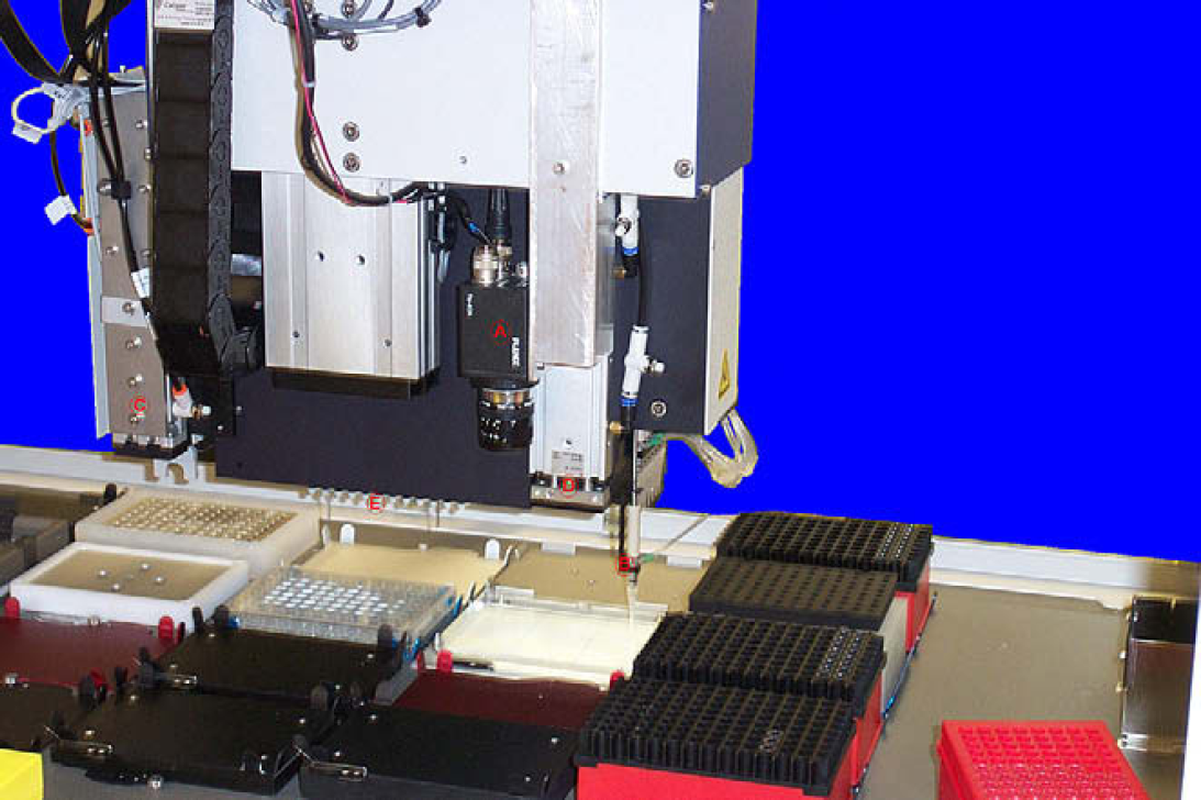
This is the back of the gantry on the Sciclone ALH 3000. A. The CCD camera mounted on square aluminum tubing. B. One of the Z-8 probes extended in the pick position. C. The gripper used to de-lid plates and move plates and tip boxes. D. The bulk dispense tool used to add growth media into the plate to grow cells up. E. A 96-disposable tip head. Not used in this application.
The other devices located on the gantry (Fig. 1) include a right gripper, used to move plates and remove lids, and a bulk reagent tool (D) used to add growth media to the growth plates.
A light source is necessary to illuminate the agar plate and enable the CCD camera to capture good images of the colonies. The deck of the ALH 3000 has a number of open positions in the deck for mounting shakers, heater/coolers, and other devices. Position C2 is ideal for locating the light source because it allows the Z-8 tips to reach any position on the plate for picking. Figure 2 illustrates how the light source is setup on the system with the calibration plate in place. The light for the light box is provided by two 6-in. fluorescent bulbs shining up through the opening at deck position C2.
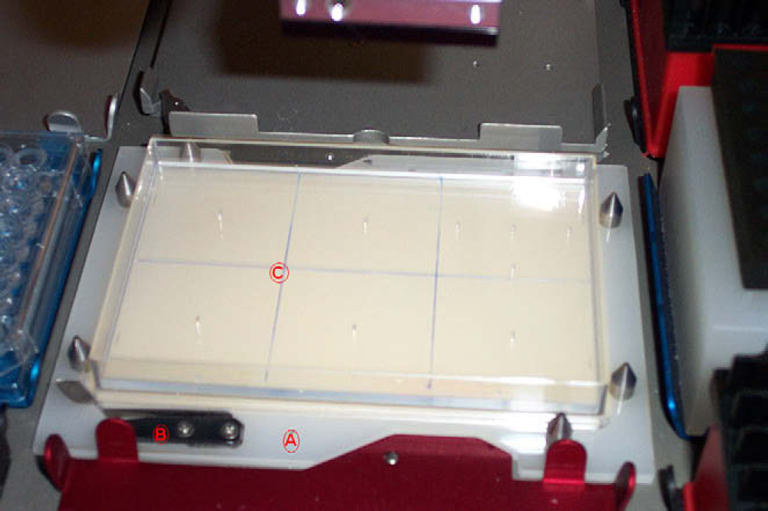
A. The light box is made of a piece of translucent plastic with pin to hold the plate in a fixed position. B. There is a spring that pushes the plate into upper right corner of the light box. Under the deck are two small florescent lights that illuminate the colonies. C. The plate here is the calibration plate that I had made to calibrate the picking system. It has some holes and markings at known fixed positions that are used in calibrating the system.
The Sciclone ALH 3000 used for this application is part of an Affymetrixs GCAS system and contains a twister robot that could feed tips and plates, allowing the robot to handle multiple colony source plates, boxes of “picking” tips, and destination plates. Figure 3 illustrates the deck layout for the colony picking application. As shown, this setup has a colony source plate at C2, five boxes of 50-μL “picking” tips, and five microtiter plates to receive the colonies, enabling the system to pick up to 480 colonies from each colony source plate.
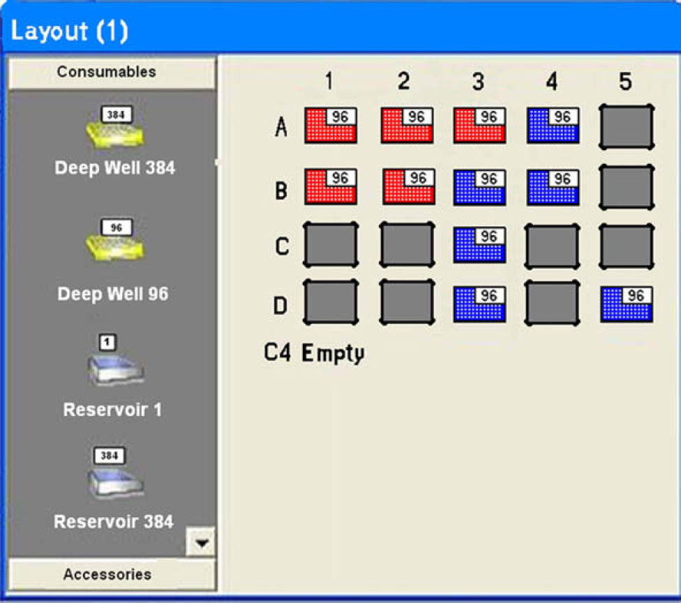
The deck layout of the ALH 3000. Position C2 is where the colony plate will be placed. With five boxes of tips and five plates, the system can pick up to 480 colonies per run.
Software
The top level or software for this application uses the standard software package for controlling the Sciclone ALH 3000. This software is designed to move the gantry, control the gripper, Z-8, bulk dispenser, and all the hardware on the ALH 3000. The Sciclone software also has the ability to upload and download Microsoft Excel spreadsheets, run Excel macros, and launch Windows program. The Excel link in the software is used to pass the X, Y location of the colonies from a spreadsheet to the Sciclone software for picking. The ability to run Windows programs is used to launch a small visual basic program written to capture the colony plate images. The Sciclone software will also run a macro in ImageJ 1 that is used to locate the colonies within the images.
Within the Sciclone software, the application is at the highest level, in terms of control, and consists of methods and global variables that are available to all applications and deck layouts. Methods are the basic building block of the application and are made of steps designed to control the hardware and contain local variables and parameters that are only available to that method. Any method within an application can be used for initiation. As a result, applications can have more than one starting point. We have exploited this capability in the colony picking application to enable the main colony picking application and separate methods for calibrating the system to be stored in a single application module.
The first step in the colony picking application is to capture images of the colony source plate (see Fig. 4). This is done by positioning the gantry housing the attached camera at six different reference locations and launching the Visual Basic program at each position to capture and save the image. The VB program uses the Active X controller called Video CapX (Fath Software, Travnik 72270, Bosnia-Herzegovina) to capture the image and save them as jpeg files. Two of the global variables, called Zand Y, in the Sciclone application software, are used to store the X, Y coordinates where the gantry camera captures the first image. There are two other global variables called global X spacing and global Y spacing to get to all six locations to capture the images. The location where the gantry captured each image is the reference for picking the colonies in that image. Because the camera is mounted to the same gantry that the Z-8 probes are located on, the picking X, Y relationship between the image and the probes is fixed. To calibrate the system, the relationship between the image and the probes must be measured and stored in the Sciclone application software so that the system can accurately place the tip on the colony for transfer.
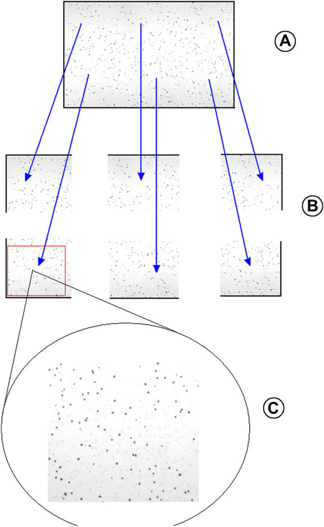
A. The colony plate. B. Six images are captured to cover the complete colony plate. C. The images are then cropped and set to scale before the colonies are located on the six images and stored in a file for picking.
ImageJ is the heart of the image processing software. The software is public domain open source and comes with a suite of macros, including particle analysis, which locates particles in an image according to shape and size. The software also contains both scaling factor settings and a built-in results table. The scaling factor is used to set the length and width of the pixel in the image, whereas the results table is used to store the X, Y location of each colony to be picked. Two macros were developed for locating colonies. The first determines the colony locations using the particle analysis macro. The image is first sized and set to scale. Then, the gray scale is enhanced to better distinguish blue colonies from the white colonies. Finally, the particle analysis macro is run to locate the colonies within a size, gray scale, and specified circularity range. You then are presented two images to compare for each segment, the first is the raw cropped image and the second is an image showing only the colonies that will be picked. You then have the option of changing the selection parameters and reevaluating the image or accepting the images presented. The colony locations are stored in one of six Excel files, one for each image. Because some colony plates are too densely populated for the limits of this macro, a second macro was developed that allows the operator to select the colonies to be picked. This second macro crops and sizes the six images just like the first, but places the images on the computer monitor for the operator to choose the colonies to be picked using the mouse for selection. As they are selected, their location is stored in the result file that is then broken up into the six individual Excel files (one for each image) for subsequent picking.
The image processing system is also used to calibrate the eight Z-8 probes. All automated liquid handlers require regular calibration. Because this application requires tighter tolerances than typical liquid handling, a method for rapid calibration and alignment of all eight probes is necessary. This method was developed using the same imaging system that is used to locate the colonies.
A calibration plate was constructed from the same type of plate typically used for colony picking. A 3.175-mm thick clear plastic plate was inserted into the plate (see Fig. 2). This plate has a 1-mm hole drilled in at the center of each of six segments. Four other holes were place 15 mm up, down, left, and right of the center hole in segment 1. The next step is to determine the scale for the imaging plate. This was accomplished using the scale method in the colony picking application that places the gantry at the segment 1 position, taking an image of the calibration plate. Image J by default has no scale, all measurements are in pixel units, not millimeters, as required by the Sciclone ALH 3000. Using the image captured in Image J, the number of pixels separating the holes spaced 15 mm above and below the center hole can be determined. Dividing the number of pixels by the predetermined spacing of 30 mm allows for the calculation of the number of pixel per millimeter (10.92 pixels per mm). The same process was followed for the left and right holes to insure that the horizontal scale and vertical scale are the same for the camera.
Once the scaling factor is determined for the calibration plate, these values are used to calibrate the X, Y location of each probe on the Z-8. Each probe will have an X and Y offset value. For probe 1, this will be the amount the gantry must move in the X and Y direction to put probe 1 in the center of the 0,0 location (center hole) of the image. The other seven probe offsets will be relative to that of probe 1. In theory, the offset for probe 2 should be 0 mm on the Y axis and 9 mm on the X axis. The other six probes should each be 0 mm on the Y axis and the X axis offset should increase by 9 mm as you get farther from probe 1. These default values are just a starting point. They are not accurate enough to perform the picking. By measuring the probes actual locations and storing the corresponding X, Y offsets the software can compensate for mechanical errors in the alignment and accurately place the tips on the target colonies.
These inherent inaccuracies can be accurately measured by marking eight tips, mounted on the Z-8, with ink by contacting an inkpad at one deck location followed by marking eight spots on the calibration plate. Probe 1 locates to X = 15 mm, Y = 6 mm in the first image segment, with 0,0 being the center hole in that segment. Probe 2 locates to 3 mm below probe 1 at X = 12, Y = 6 and places a spot. The other probes follow, each 3 mm below the other. The gantry then travels to the image location to capture an image of the first segment that includes all the spots from the eight probes (Fig. 5). An Image J macro is run that allows the operator to select the center of the nine spots in order. First the center (0,0) hole, followed by the eight spots deposited by the tips in order from probe 1 to 8. Each time a spot is selected, its X, Y location is entered into the results table. Once all spots are recorded in the results table, it is saved as a .csv file, allowing the calibration method to analyze it. The method can then calculate a new X and Y offset for each probe based on the theoretical value verses the measured value. The calibration method is typically repeated with the same tips, rotated 180°, to see how the runout in the tips effects the calibration. This calibration method also looks at the 0,0 location marking the center hole of segment 1 and adjusts the X, Y variable to place that center hole at 0,0 on the image.
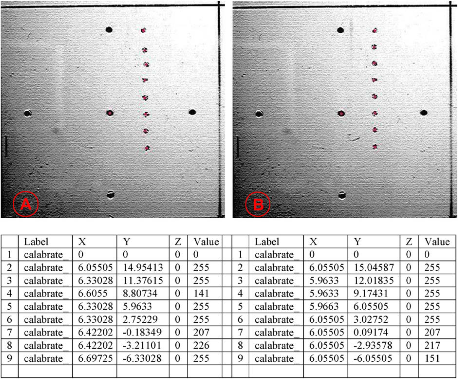
A. The image and corresponding results table before running the calibration procedure on the Z-8 probes. Note the uneven spacing between probes in the Y column; they should be 3 mm apart. The X column should all be at 6 mm. The largest error is 0.5137 mm for probe 7 in the X column. Record 1 is the 0,0 center hole of the segment. B. The image and corresponding results table after running the calibration method. Note that the spacing in the Y column is much close to the 3 mm value. The X column does not vary more than 0.1 mm from the desired value of 6 mm.
The system should be calibrated before the first colony plate is run and any time you do not know the condition of the Z-8 alignment. With the system calibrated, it is ready for use. The rest of the steps in the application use standard Sciclone method steps. After the images are taken and the colonies are located the method simply loads the tips eight at a time and picks the colonies. The tips are placed on the colonies, aspirating 1 μL. The tip can be set to perform a wiggle move that simply moves the tip 0.1 mm in each direction. Once the eight tips have picked the colonies the tips go to the growth plates to inoculate the media and then the tips are changed in preparation for the next set of eight colonies to be picked. If it is the first time the growth plate is accessed the lid is removed first and the plate is filled with growth media. The method then continues in this fashion until all the colonies are picked or it runs out of tips or growth plates.
Conclusions
Following a simple “retro-fit” scheme, most standard liquid-handling robots can be “upgraded” to include high-throughput colony picking capabilities. As described, this upgrade requires only the addition of a CCD camera and software. This modification extends the utility of the standard liquid-handling robot without the expense and space constraints associated with a typical colony picking platform.
The developed colony picker takes about 7 min to pick a 96-well growth plate once the images are collected and processed. The time it takes to locate the colonies depends on the technique used to locate then. Using the self-select technique, the operator must click on each colony to be picked. Using the more automated method, the operator just set the picking criteria and the analysis macro selects the colonies that fit the criteria.
One improvement that is planed for the next version is changing the imaging system to a “dark field” system. This would put the colony plate on a flat black surface. The white colonies would have more contras against the black background and the blue ones would blend more into the background. This would improve the automated selection of colonies.