
Abstract
Microfluidic cell culture is a promising technology for applications in the drug screening industry. Key benefits include improved biological function, higher-quality cell-based data, reduced reagent consumption, and lower cost. In this work, we demonstrate how a microfluidic cell culture design was adapted to be compatible with the standard 96-well plate format. Key design features include the elimination of tubing and connectors, the ability to maintain long-term continuous perfusion cell culture using a passive gravity-driven pump, and direct analysis on the outlet wells of the microfluidic plate. A single microfluidic culture plate contained eight independent flow units, each with 104 cells at a flow rate of 50 μL/day (6 min residence time). The cytotoxicity of the anticancer drug etoposide was measured on HeLa cells cultured in this format, using a commercial lactate dehydrogenase plate reader assay. The integration of microfluidic cell culture methods with commercial automation capabilities offers an exciting opportunity for improved cell-based screening.
Introduction
The development of microfluidic technologies will have significant impact in the field of cell biology. 1 The key advantages over traditional microtiter plates include controlling the 3D culture environment, 2 taking advantage of the physical and fluidic properties of the microscale, 3 and creating multiplexed nanoliter arrays for improved biological analysis. 4 The end result of these capabilities will provide the drug screening industry with improved biological data, new classes of cell-based assays, and a reduced cost and reagent consumption per data point.
Recent advances have been made to tailor micro-fabricated environments for improved cell culture experimentation. The first wave of innovation occurred over the past 5 years, as microfabrication methods began to be applied to provide robust microfluidic cell culture. 4 –12 The major focus of these research efforts was to replicate the typical operations used during cell culture, such as cell seeding, nutrient perfusion, fluorescent staining, and data collection. 13 This burst of “proof-of-concept” demonstrations provided promising leads for the automation industry, such as applications in high-throughput screening, high content analysis, cellular systems biology, and the extension of the “omics” revolution to the cellular scale.
The critical next step in the development of microfluidic systems for large-scale application is to address the “commercialization” issues such as ease of use, industry relevance, and reduction of cost. 14,15 In this current work, we describe a method to integrate microfluidic cell culture into a potentially automated process using the traditional 96-well format. This will allow operation of microfluidic components using equipment familiar to a standard automation laboratory. To our knowledge, this is the first work to focus on research toward delivering a microfluidic cell culture format for this purpose. Continued development and integration of this methodology into the research and screening laboratory will enable the benefits of microfluidic technology to be applied in a more practical and widespread fashion.
Design and Methods
Microfluidic Design and Fabrication
The microfluidic components were fabricated using soft lithography molding as previously described. 16 First, the microstructures were patterned onto a 4-in. silicon wafer using standard photolithography and etching methods. Various height features were designed either using different photoresist thicknesses (SU-8 series) or etching times. After the silicon mold was created, the silicone elastomer polydimethylsiloxane (PDMS) was poured over the mold and allowed to cure. The PDMS was then backed with a laser-cut acrylic sheet and bonded on the bottom to a glass microscope slide, enclosing microfluidic circuit. An oxygen plasma bonding method was used, creating a hydrophilic internal channel surface on the PDMS. Immediately after bonding, the device was primed with aqueous solution, preserving this hydrophilic property. Our typical cell culture unit consisted of a 2-μm tall barrier channel and a 30-μm flow channel. Details of the mass transport properties of this configuration can be found in a recently published scientific paper. 17 The key function of the microfluidic culture region was to maintain adherent or nonadherent cells in a specified location for long-term continuous perfusion culture similar to a bioreactor.
96-Well Plate Interface
The inlet and outlet ports of the microfluidic culture unit were designed to fit a standard 96-well plate. After the process described above, the microfluidic devices were bonded to the bottom of a drilled 96-well plate using an adhesive such that the fluidic reservoirs of the plate led directly into the microfluidic channels. The total thickness of the microfluidic component was 1.5 mm, which did not protrude beyond the bottom frame of the 96-well plate. Therefore, the overall footprint of the device was identical to a standard plate and should not affect automation robotics. Each single culture unit covered 5 wells of the 96-well plate. These represented (1) medium inlet, (2) cell inlet, (3) cell outlet, (4) cell culture area, and (5) medium outlet. The prototype fit eight independent flow units on a single plate (one for each row) to demonstrate multiplexing. In the future, it is easily scaled to fill the entire plate or adapted to a 384-well format. The entire fabrication process used optically transparent materials; therefore, the cells were easily accessed via microscopy. To facilitate automated imaging of the microfluidic plate, the cell culture area was located in the center of the fourth well.
Cell Loading
To properly transport cells into the microfluidic culture area, we developed a mechanical cell-loading system. This apparatus used air pressure to drive flow of cells in solution from the well reservoir into the microfluidic channels and subsequently into the cell culture areas as previously described. 17 This system consisted of two parts: (1) A 96-well plate format manifold and (2) a flow switch. The manifold was designed to seal over the microfluidic plate using a vacuum, allowing air pressure to be applied to each of the fluid reservoirs. The flow control panel allowed regulation of compressed air (0–10 psi) and switching of flow. Cell loading was performed under a microscope to ensure uniform numbers and density.
Microfluidic Cell Culture
Each microfluidic culture region was designed to accommodate 104 mammalian cells. After the cells were localized to the microfluidic culture regions, excess cells were washed out of the flow channels using phosphate buffered saline (PBS). Three hundred microliters of cell culture medium (Delbecco's Modified Eagle's Medium [DMEM], 10% fetal bovine seron [FBS], 1% non-essential amino acids [NEAA], 1% Na–Pyr, and 1% penicillin/streptomycin/amphotericin B [PSA]) was then dispensed into the inlet well and the plate was placed in a cell culture incubator (37 °C, 5% CO2) for long-term culture. The microfluidic culture plate was designed to provide continuous flow of medium to the cells using a gravity-driven method. The low Reynolds number of the microfluidic flow (
Lactate Dehydrogenase Toxicity Assay
HeLa cells were cultured in the microfluidic plates to demonstrate a cytotoxicity assay. Etoposide (1 mM; Sigma) was prepared in DMEM (HyClone, 5% FBS, 1% PSA). DMEM with no drug and 2% DMSO was used as the positive control. Twenty-four hours after loading cells into the microfluidic plate, all contents of the media inlet and outlet were aspirated and 250 μL of drug solution was pipetted into the media inlet. The microfluidic plates were then placed in the incubator for 24 h of drug exposure. Lactate dehydrogenase (LDH) levels in the outlet wells were measured using the Cytotox 96 Non-Radioactive Cytoxicity Assay (Promega) and recorded on a 96-well plate reader (Biotek).
Results and Discussion
In a previous work, we developed a microscale cell bioreactor that effectively localized cells into an enclosed 3D microenvironment while providing continuous nutrient flow for long-term culture. 17 This was based on the use of a microfluidic barrier that separated cell culture areas from nutrient flow paths, solving the problem of channel blockage in traditional microfluidic cell cultures (Fig. 1). Here, we describe the integration of this microfluidic culture concept into an automatable format. The key innovation was the use of a 96-well plate interface for liquid handling. This was accomplished by routing the microfluidic inlets/outlets to the center of the wells on a microtiter plate, drilling through holes using a laser cutter, and bonding the microfluidic component to the bottom of the plate. This eliminated the need to use tubing connections and syringe pumps, which prevent current microfluidics from operating in an increased throughput process.
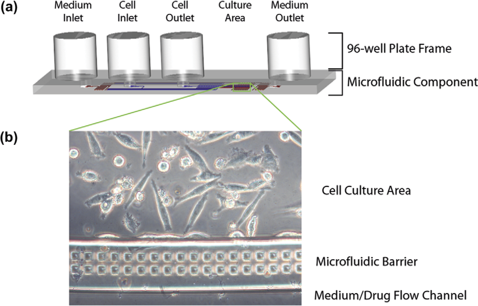
Microfluidic cell culture unit. (a) The microfluidic channels were fabricated into a PDMS polymer layer and bonded to acrylic (top) and glass (bottom) to form the enclosed “microfluidic component.” Access holes between the microfluidic channels and the wells of a microtiter plate allowed direct liquid interfacing with a 96-well plate frame. A single fluidic unit covered five wells, corresponding to (1) medium inlet, (2) cell inlet, (3) cell outlet, (4) microfluidic culture area, and (5) medium outlet. The fluidic network in the microfluidic region was designed to control cell localization and mass transport, as previously described. 16,17 Schematic diagram is depicted to scale. (b) The microfluidic culture region consisted of three parts: A cell culture area for localized cell adhesion and growth, a flow channel for medium/drug introduction, and a porous microfluidic barrier to separate the two flow paths while enabling rapid diffusive transport to the cells.
A prototype system was designed for loading cells into the microfluidic culture units (Fig. 2). This worked by sealing a pneumatic manifold over the wells of the plate, and applying positive pressure to drive flow of individual wells into the microfluidic channels. The flexibility of the system to control flows allowed a wide range of capabilities, including cell introduction, cell washing, on-chip assay, cell lysis, flow switching, and flow-rate regulation. The design of the flow system was also amenable to automation, as the additional plate-handling step was the sealing of the gasket to the top of the microfluidic plate. Using an air pressure-driven pump meant that the manifold did not make contact with samples, allowing multiple plates to be operated in series. An additional advantage was that once the cells were loaded into the system, the plate no longer needed to be operated in the flow system during long-term culture and analysis.
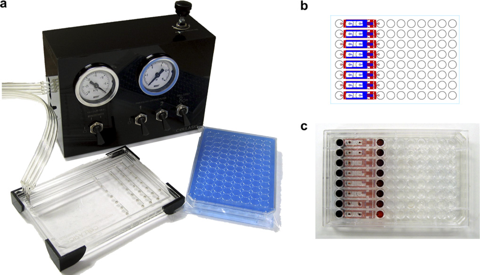
System design. (a) The prototype system consisted of two parts: The microfluidic plates and a cell-loading manifold. The microfluidic plates operate essentially the same as a microtiter plate, with the key difference of the cell-loading step. To pump the cells from the reservoir wells into the microfluidic channels, air pressure was supplied through the cell-loading manifold. (b) Schematic layout and (c) photograph of the eight-unit microfluidic culture plate. The current design incorporated eight independent flow units in each row of a 96-well plate.
The operation of the current microfluidic system is laid out in Figure 3. The process was intended to be as similar to current cell culture screening protocols as possible. In the first step, cells and sample solutions were dispensed into the appropriate wells of the microfluidic plate. The plate was then transferred to the cell-loading system to transport the cells into the microfluidic culture regions. This process typically operated at 1–5 psi pressure for 2–5min. Excess cells could then be washed out of the system using a buffer solution as previously described. 4 Once the cells were loaded, the plate could be handled similar to a typical 96-well dish. Stacking of the plates into a cell culture incubator enabled long-term continuous flow culture. This was achieved without the use of external pumps via a passive gravity flow method. After the desired culture time, the plates were treated with drug, assay reagents, and analyzed using microscopy or plate-reading methods.
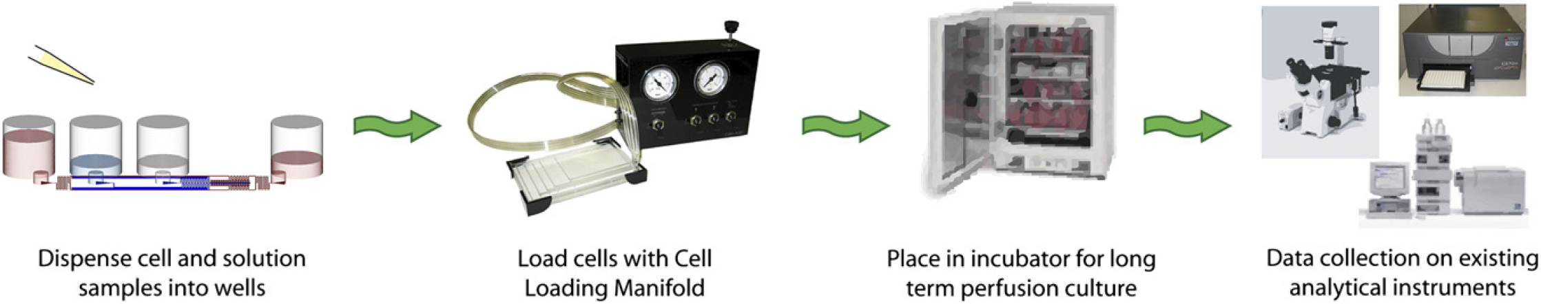
Operation process. The microfluidic culture system was designed to be compatible with standardized screening instrumentation. In the first step, cell and liquid samples are dispensed into the microtiter wells. The cell-loading manifold then drives the cells into the microfluidic culture region. Currently, this step is not automated; however, it is conceivable that a stand-alone module can be engineered to serve this function. After the cells are loaded, the plates can be treated as standard 96-well units, such as culture in an incubation chamber and analysis using microscopy or a plate reader.
A key aspect of the cell culture plate design was the ability to maintain long-term continuous perfusion without the use of an external pump. This allowed automated culture without the development of completely new incubation and flow systems. Due to the small volume and scale of the microfluidics, gravitational force was sufficient to result in fluid flows in the physiologic range. Careful calculation of the fluidic resistances of the microfluidic circuit allowed the tuning of flow rates from 1 to 500 μL/day (Fig. 4). The current culture plate was set to flow at 50 μL/day. Empirical measurement over a 24-h period resulted in a flow rate of 46 ± 5 μL/day. At this flow rate, the cells (104 per unit) were exposed to medium flow with a velocity of 4 mm/s with a total residence time of 6 min. For long-term cultures, the medium can be replenished by dispensing the required amount into the inlet well.
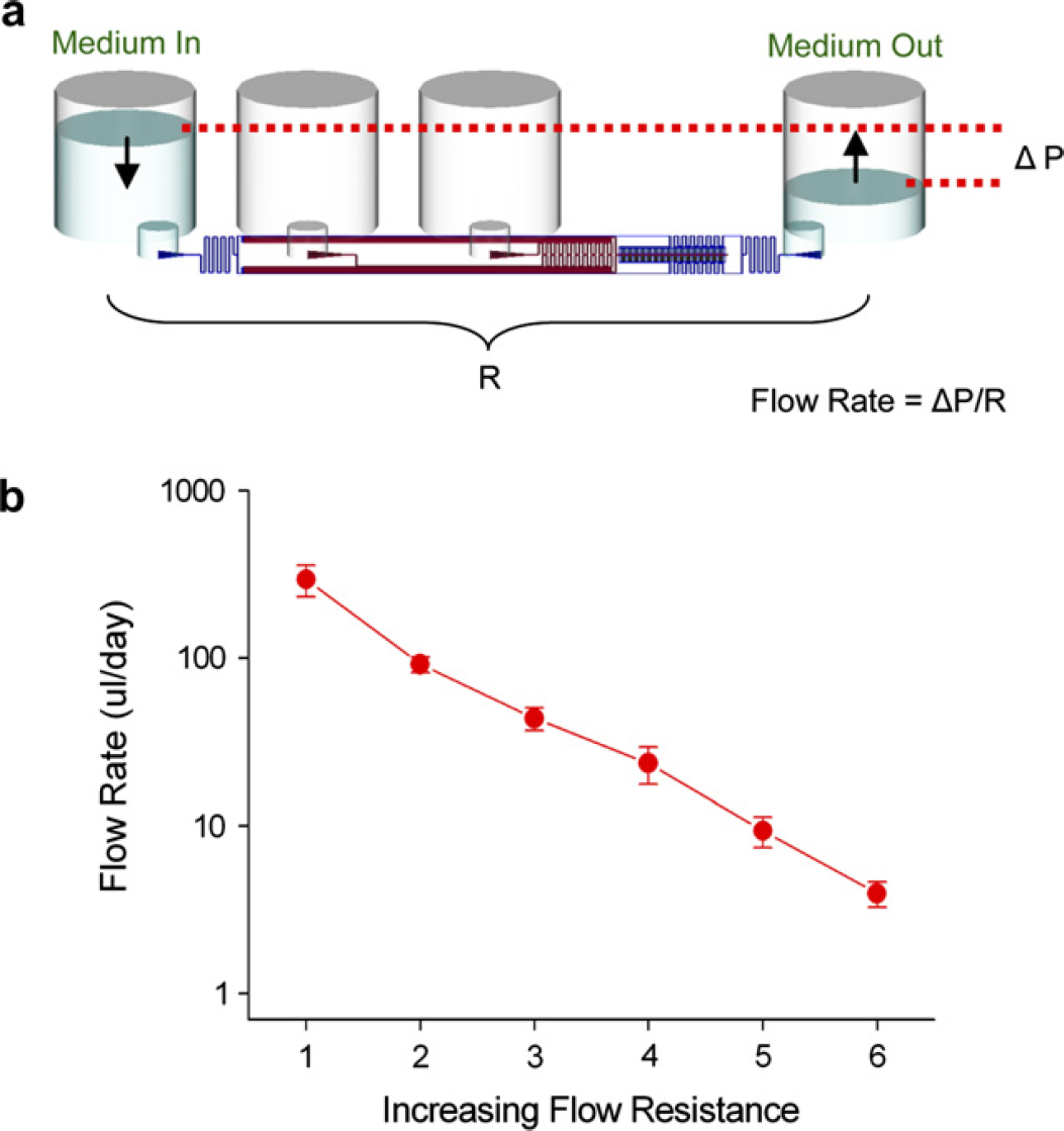
Gravity-driven perfusion culture. The microfluidic plate was designed to operate without any external pumping mechanisms to enhance automation capability. (a) The flow rate through the cell culture channels is given by the pressure drop divided by a fluidic resistance term (Δ
To demonstrate a cell-based assay using this microfluidic format, a standard cytotoxicity assay using LDH activity was performed. The LDH assay detects loss of membrane integrity through the release of LDH enzymes from compromised cells. The anticancer drug etoposide was exposed to cultured HeLa cells for 24 h with continuous flow on the microfluidic plates. Cells exposed to no drug (+ con) and 1 mM etoposide were run in quadruplicate on a single plate and assayed for LDH release (Fig. 5). With no drug, the 24-h viability of the HeLa cells was 85 ± 17%, whereas the drug-treated cells had a diminished viability of 7 ± 1%.
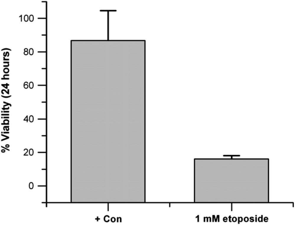
Cytotoxicity screening. The anticancer drug etoposide was exposed to HeLa cells in the microfluidic plate for 24 h at 0 and 1 mM and cell death was measured via an LDH assay with data collection on an absorbance plate reader.
The importance of automated microfluidic cell culture is twofold. First, is the well-established goal of cell and reagent savings for large-scale screening. Second, and perhaps more important, is the ability to engineer improved culture environments to derive higher quality and more physiologically relevant cell-based data. The described prototype is a first step toward solving both these issues. In traditional microfluidic cell culture, the use of syringe or peristaltic pumps prevents volume reduction. In the microplate-based microfluidic format described here, it is fairly straightforward to scale to 384- or 1,536-well formats without affecting the local cell environment, because only ∼ 1 μL is needed to fill the microfluidic components. It is important to emphasize that standardizing microfluidic cell culture methods and making it readily accessible to the typical research lab is a critical step for translating the novel biological aspects of this technology into industry practice.
This work demonstrates the first steps of integrating microfluidic cell culture technologies with current automation tools. With the described prototype, it is possible to conduct long-term cell culture experiments with minimal modification of current protocols. The only step that requires specialized equipment is for cell loading. The feasibility of creating an automatable solution was demonstrated in the current prototype system. With continued development, this module can be scaled for higher throughput automation, similar to the current 96- or 384-well liquid dispensers. The proof-of-concept cell-based screen conducted in this work involved drug-induced cytotoxicity of HeLa cells cultured for 24 h in the microfluidic plate format, and assayed using the LDH assay and a plate reader. Due to the parallel nature of the process, multiple culture plates can be incubated at one time, making the total assay time similar to current automated culture methods. With continued development, it is expected that the capabilities of microfluidic cell culture will allow automated cell-based screens to be conducted at reduced cost, increased data quality, and higher throughput compared with the current industry standard.