
Abstract
A variety of features used by our Department in the design and integration of Automation Platforms are presented here. A challenging project for any automation group is the automation of NMR sample preparation. The dispensing of highly volatile or viscous solutions into the typical 5 mm ID NMR glass tube, and the subsequent capping of the tube, presents unique problems. An angled incremental single-channel dispensing technique prevents bubble formation when a 10-mM protein—based solute is used. A novel gripper finger design, used in conjunction with in-house fabricated Teflon caps, allows reliable capping of NMR tubes. In situ vortexing minimizes vial handling with increased throughput. Magnetic mounting of robot tools (hands) provides precise snap-in positioning with collision-safe breakaway. This simplifies crash recovery during development testing and production use. A wraparound Safety Enclosure with modular safety circuit fulfills ANSI/RIA R15.06–1999 Safety Requirements. Flexible control software permits run interruption for loading and preparation of additional NMR tubes. Prepared samples may be removed during run interruption. A “Fly-By” barcode scanning tool enables positive compound sample ID with improved throughput. Preexisting instrument control software is conveniently interfaced to a Scheduler application through an open-architecture instrument integration framework. This framework allows the development of automation platform—independent Middleware for schedule and assay portability. A new generation of low-power, lightweight, portable and expandable platforms is also presented where a building block tandem approach is used in conjunction with the Rent-a-robot concept for robot recycling.
Keywords
Introduction
The nature of pharmaceutical research has changed in the last 50 years from a benchtop-centered approach to one that takes advantage of modern automation capabilities. Our department, Biomedical Engineering, has served as an internal research and development group for Wyeth for the entire time.
Our approaches to the support of pharmaceutical research and development have changed in parallel with the changing demands of our customers. The past 10 years has seen a dramatic increase in the demand for high-speed sample preparation and experimentation. Thus, we have embarked on an ambitious program to develop a series of highly modular and easily fabricated robots, which can be quickly adapted to the myriad techniques that our customers use.
Our experience has been that a few standard structural frameworks will suffice. The real need for customization is in the devices that manipulate the researchers' “objects of science”—namely the vials, multiwell plates, pipette tips, dry powders, solvents, lids, caps, barcode labels, liquids, and countless other items which are required to prepare samples and conduct experiments.
Although the simplest approach may have been to ask the researchers to conform to our vision of the most automation-friendly way to perform these assays, we chose instead to create a simple robotic platform and develop the design and fabrication expertise to create nearly whatever device they need and incorporate it into our structural platform.
We relate here the successful outcomes of this effort. In addition, we describe the safety considerations, which are part of the development of any new laboratory device. We finish with a discussion of our efforts to sustain the development of the automation through a robot recycling strategy and the creation of a small portable robot platform.
System overview
A good showcase of this philosophy is the automation of NMR sample preparation. The preparation of samples into NMR tubes is a delicate and tedious process involving a wide range of liquids. From low surface tension chloroform to viscous 10-mM protein–based solutions, the dispensing of highly volatile or viscous solutes or solvents into the typical 5 mm OD, 0.34 mm thin wall NMR glass tubes, and subsequent capping, presents unique problems.
Two similar robotic systems are used to prepare samples for NMR spectroscopy. The robotic systems are based on the Wyeth Advanced Robotic Platform for Automation (WARPA) (Fig. 1) and have the ability to automate the reading of the barcode labels of the incoming samples, dilute the samples using different solvents, fill the NMR tubes without air entrapment or bubbles, cap the NMR tubes, and provide a tracking record to the sample management system downstream.
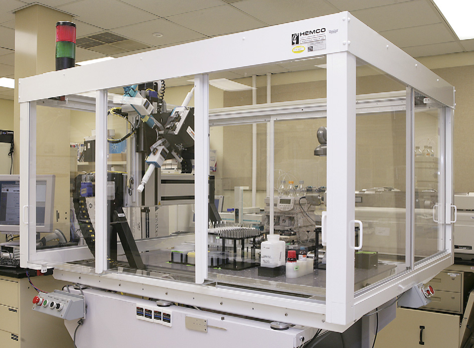
WARPA 8B—Discovery Analytical Chemistry Lab—Wyeth, Princeton. In the foreground, the WARPA unit with a safety enclosure, emergency lights, user panel to access the work surface and the racks, reservoirs, and different tools that complete the sample preparation robot.
The WARPA platform is a custom gantry style robot consisting of X, Y, Z linear servo-driven axes with positional resolution of 1/41615 of an inch. The gantry is a 39 in. by 21 in. XY Table P/N: HL32SBM201205405 with a 10 in. travel Z-slide PN: HL31SBM512050005, both from Techno-Isel, 2101 Jericho Turnpike, New Hyde Park, NY 11040. It also consists of a fourth servo-driven axis, W, using a 20602-RT Rotary Table from Parker Hannifin, Daedal Division, 1140 Sandy Hill Road, Irwin, PA 15642, to rotate the currently needed tool into the position required for its use on the deck surface. The W axis has a rotational resolution of 1/2048 of a degree. This gantry moves a set of tools about a three-dimensional workspace. Tools are magnetically fastened to the four available positions on a vertically oriented rotary table. Goldline XT brushless servomotors from Kollmorgen, 1500 Mittle Blvd, Wood Dale, IL 60191 drive each of the four axes. A DMC2180 multiaxis servomotor controller from Galil Motion Controls, 3750 Atherton Rd., Rocklin, CA 95765, controls the motors. A PIC-SERVO single-channel servomotor controller, from JEFFREY KERR, LLC, 519 Grizzly Peak Blvd., Berkeley, CA 94708, controls each tool motor.
Protocol description
The incoming samples (dry or liquid) are presented to the robot in 1-dram vials. Each sample is usually associated with a sample management data sheet, which has a unique barcode label. Alternatively, the sample vial is scanned. The vials are placed by hand into a custom orbital vortexing rack. The robot transfers a predetermined solvent to the dry compound vial located on an orbital vortexing rack unit. One to four solvents may be selected and would have been indicated on the data sheet. The vial is vortexed for appropriate mixing. The compound solution is then transferred to the small glass NMR tube. A custom cap is placed on NMR tube. The cap is made of Teflon to prevent sample evaporation, particularly important when using chloroform as solvent.
Features
The system computer maintains a Sample Log file. The computer copies sample barcode files to a UNIX share for upload to the sample management database. The Vortex time and speed are selectable. The run may be interrupted for removal of completed samples and addition of recently arrived samples. The completed samples are located on an NMR tube rack that is compatible with the NMR spectrometer robot. The complete system may be monitored remotely using a web browser and observed with a web camera with tilt/pan/zoom controls.
Functional layout
Every workstation, vial rack, pipette tip rack, vortexer caps rack and others is designed following modularization guidelines. These rules are applied to workstation horizontal dimensional design to make robot workspace use efficient resulting in high workspace-footprint ratios. The modularization guidelines are also applied to the design of tools carried out by the robot gantry to minimize interference with neighboring workstations (Fig. 2).
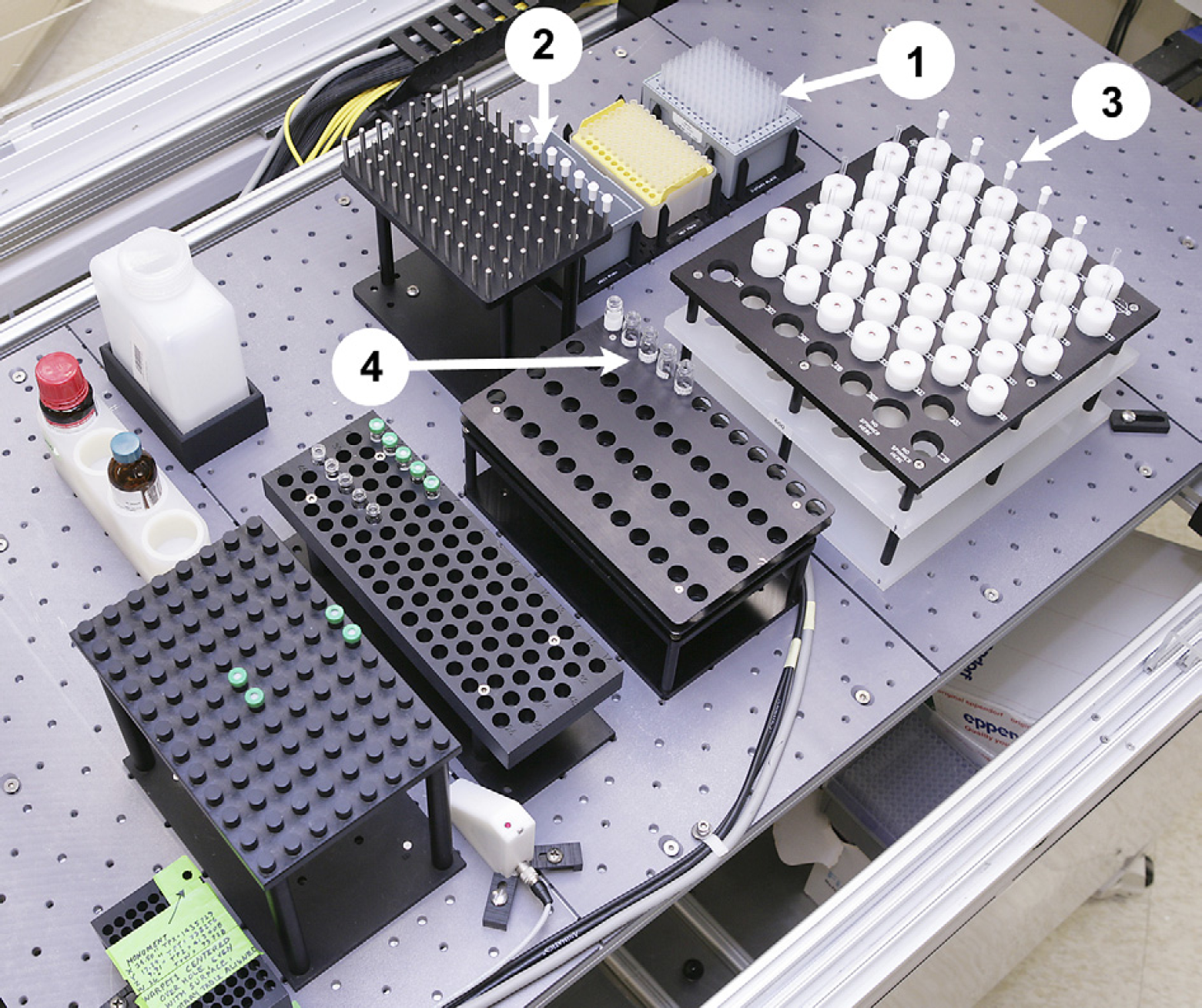
Table Layout. 1. Rack of 1250 μl pipette tips used by the custom single-channel pipette. 2. NMR cap rack holding the custom Teflon caps. 3. Removable NMR tube rack showing the tubes with their spinners used by the NMR spectrometer. 4. Vial vortexing rack with one row of vials with barcode labels.
Hardware overview
Following the modularization guidelines indicated above, and available to an in-house development group, the different racks, tip holders, and other devices used by the robot and described here, are dimensioned and fabricated to maximize the work surface and prevent interference while being accessed by the different grippers or pipettes.
Orbital Vortexer
An orbital vortexer (Fig. 3), designed using Pro/ENGINEER software (Parametric Technology Corporation, 140 Kendrick Street, Needham, MA 02494), is used to assist the mixing of the dry sample into solution. The vials are manually loaded and uncapped. The orbital vortexer smooth operation provides excellent mixing and no cross-contamination.
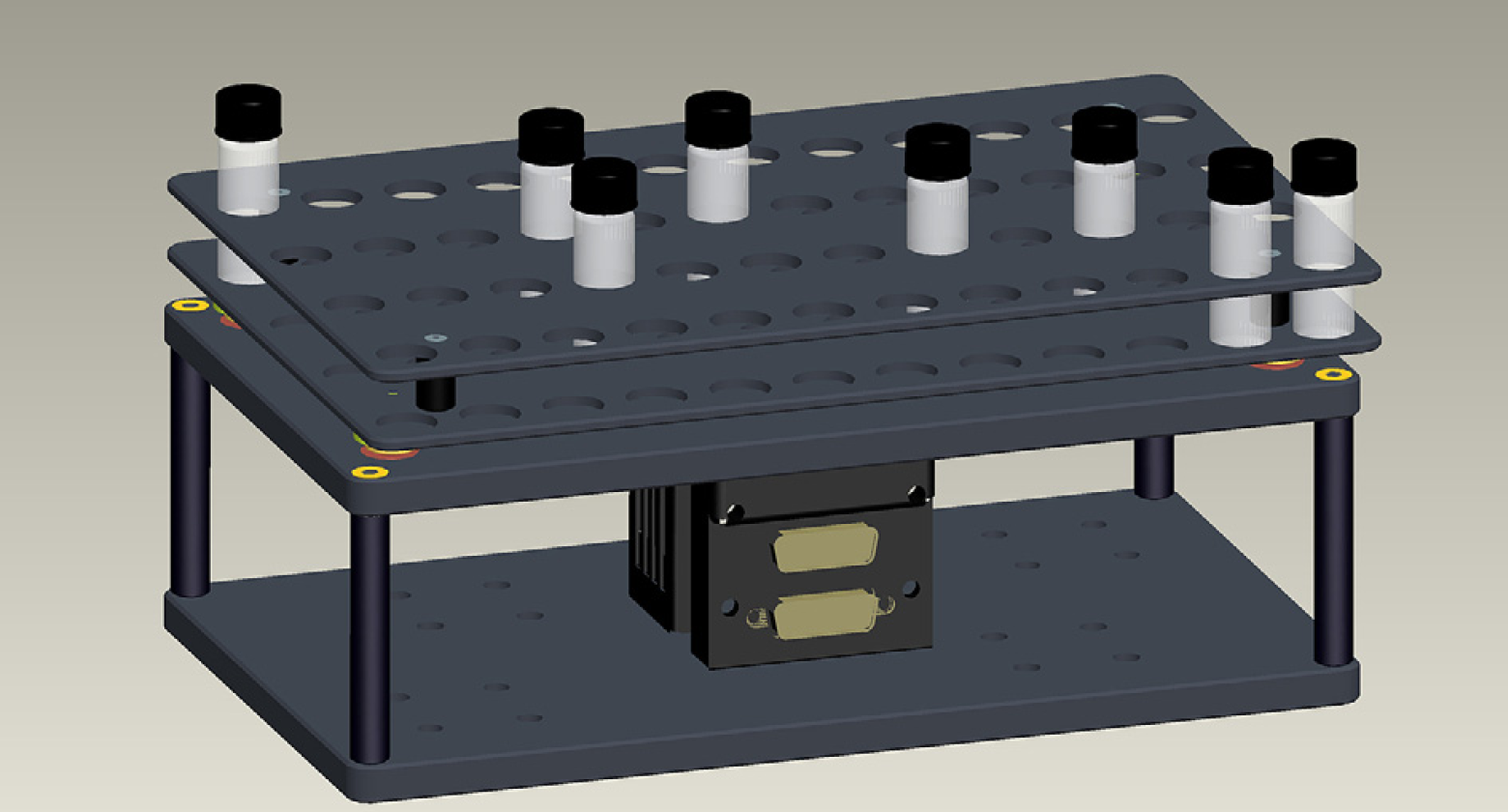
Representation of the orbital shaker as a screen image capture from Pro/ENGINEER. Longest dimension of finished component is 10 in.
Pro/ENGINEER parametric functionality and full associativity has a major impact on our productivity and modularization by providing core designs, which can be used to implement a 48-, 96-, or 12-vial racks with minor designer input.
Fly-By Barcode Scanner
A “Fly-By” barcode scanning tool (Fig. 4) enables positive compound sample ID with improved throughput and reliability. Eliminating vial manipulation increases system reliability. A scanner moved between vials on the orbital vortexer is much faster than gripping the vials and moving them to a stationary scanner.
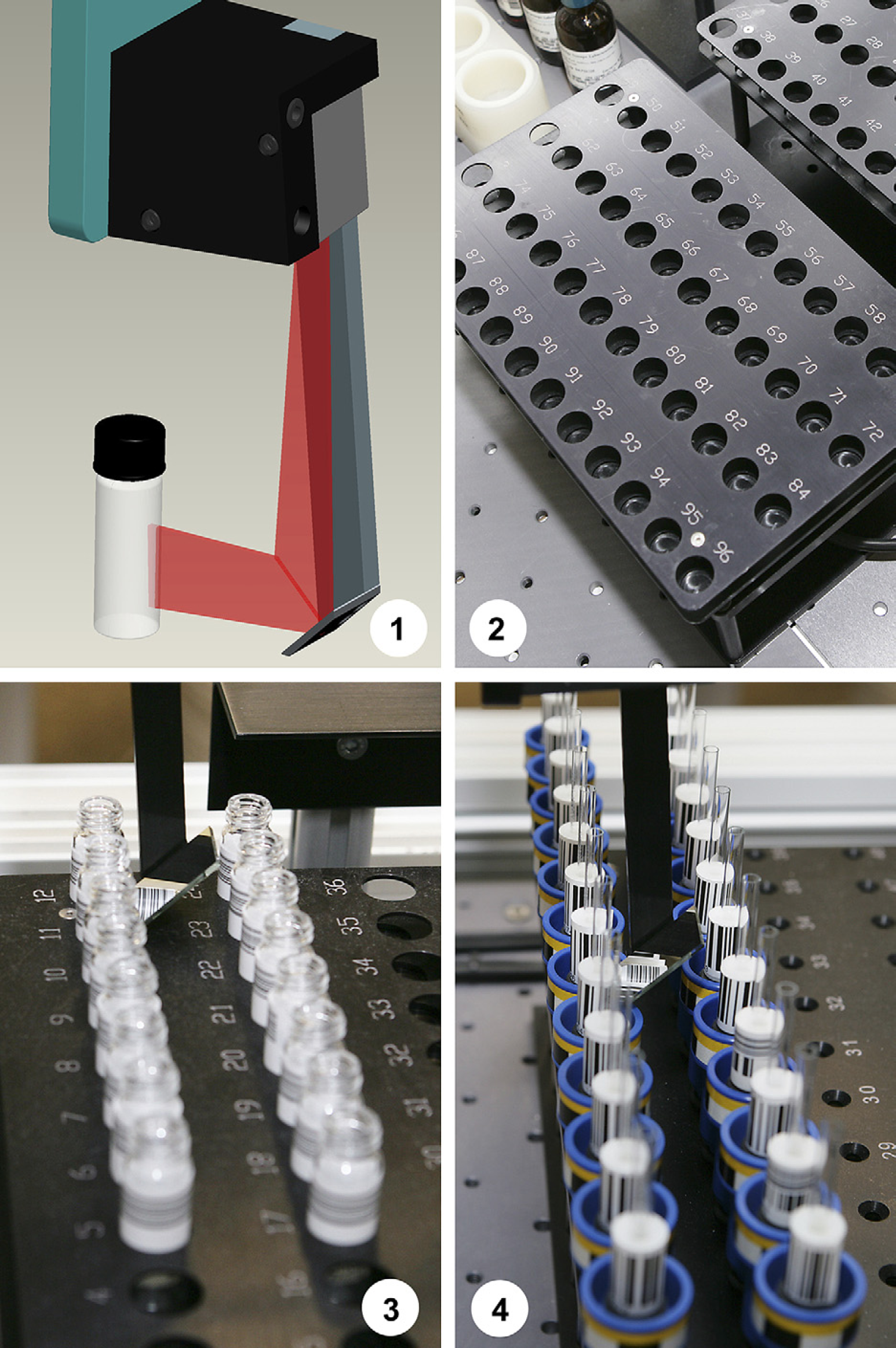
Fly-by barcode scanning tool. 1. CAD representation of the tool with an indication in red of the laser light pattern. Note that the lines of the barcode must be horizontal. 2. Racks for the vials. Note the spacing to allow for the clearance needs of the scanner. This is the same rack as indicated in Figure 3. 3. Scanning of sample vials. 4. Scanning of NMR sample collars. The scanning tool moves by the compound vials while scanning on the fly. The orbital vortexer vial rows are dimensioned to accommodate the path of the scanner mirror between them.
Rotary Table
The gantry used in the WARPA robot carries a rotary table on which up to four tools can be magnetically attached (Fig. 5) This rotary movement provides quick access to any of the four tools by a simple 90° rotation of the table.
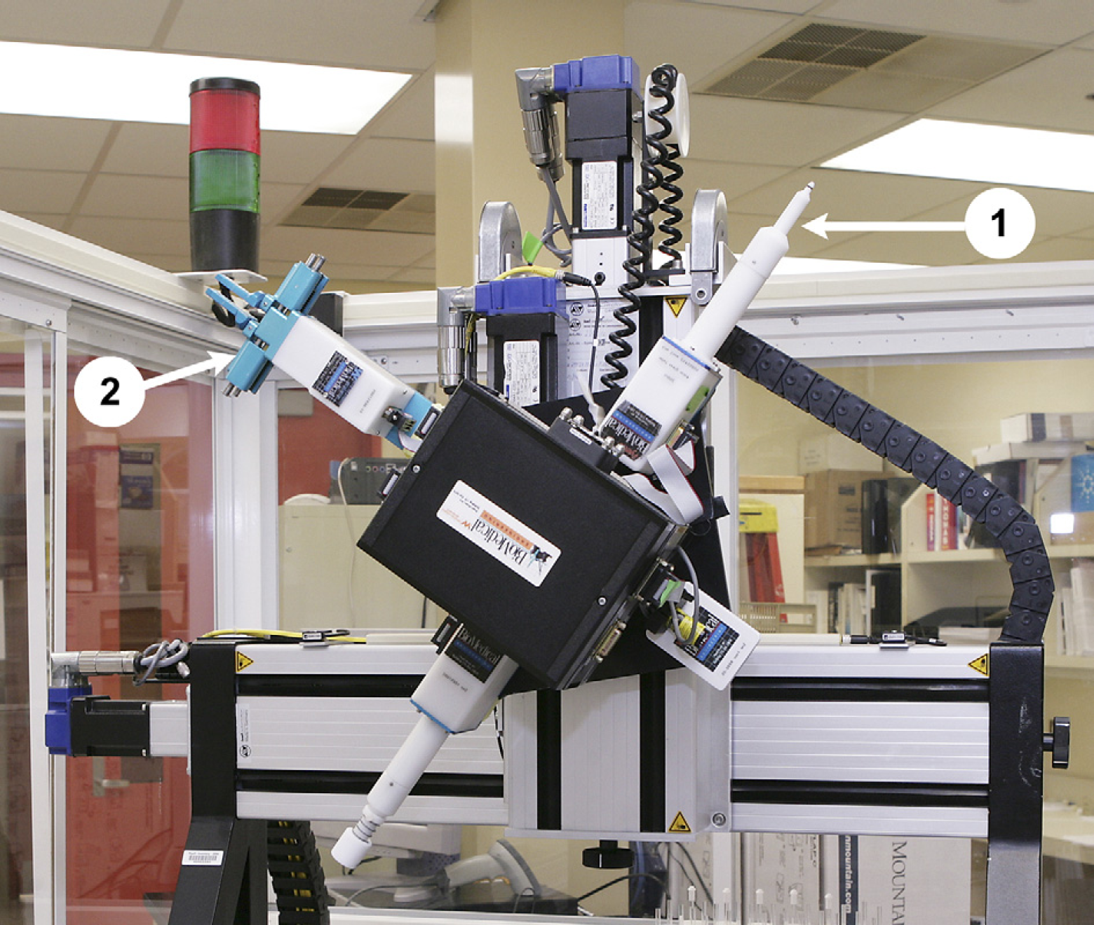
Rotary table on the gantry of the robot. Note the presence of two devices: (1) a single-channel pipette and (2) a gripper for NMR caps.
Safe Breakaway Tools
Grippers, pipettes, barcode scanners, and other robot tools are attached to the robot rotary table by means of strong magnets and locating fixtures (Fig. 6). This support mechanism provides precise and quick snap-in positioning and, at the same time, tool break away. Magnetic switches built into the rotary table detect the activation of the breakaway feature and alert the software and power circuitry such that the robot stops instantly. This scheme has simplified crash recovery during development testing and production use. At the same time, pipettes, grippers, scanners, and other elements involved during collisions are not seriously damaged and are reusable without need of repairs. No more bent gripper fingers!
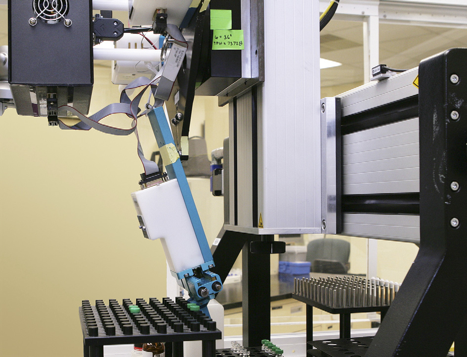
Video image of the safe breakaway feature. Note that the tool has become separated from its mounting feature and is held up by a short safety cable. At this point, the power to the robot drive circuitry has been shut down and user intervention is necessary to resume.
Gripper Fingers
Capping 5 mm diameter and 0.34 mm wall thickness glass tubes is a delicate operation. Performing this capping operation manually presents a significant risk of breaking the thin glass tube and of being jabbed (Fig. 7.1). Earlier gripper designs in our group resulted in a custom gripper with a cone-shaped entry to align glass tube and lower edge of cap (Fig. 7.2). There remained issues with consistency of cap manufacture and a tendency for the lower edge of the cap to be curled in and likely to catch on the top edge of the glass tube. Our current design consists of a custom Teflon cap and set of fingers with gripping surfaces matched to the cap external features (Fig. 7.3). These modifications provide positive and self-aligning gripping (Fig. 8).
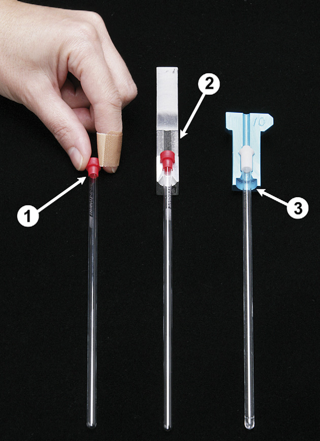
Brief history of the NMR tube cap and gripper design. 1. Manual method—note bandaged finger. 2. Early design, which used commercial caps. 3. Final design with custom Teflon caps.
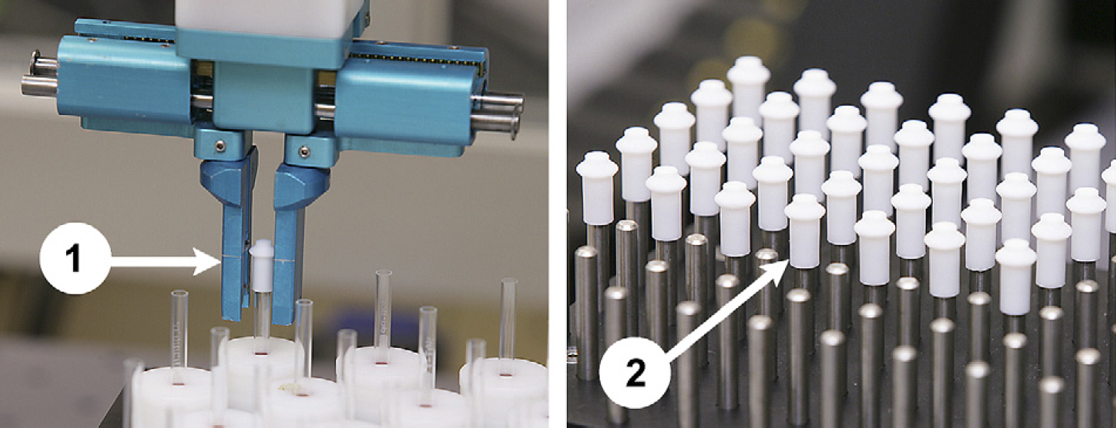
Custom gripper fingers and (2) Teflon caps.
Additionally, the use of Teflon to make the caps ensures extremely good sealing properties. Some of the samples prepared by these robots use chloroform as solvent. This solvent is known to migrate through the commercial polypropylene caps.
Angled incremental dispensing technique prevents bubble formation.
The problem of dispensing of solutions into tall, thin NMR tubes has presented a challenge for automation systems for many years. Whereas manual methods can be slow, cumbersome, and tiresome, their implementation by current automation devices has been difficult.
The problem is to fill the tube without foaming or air entrapment. The internal glass surface of a brand new and dry NMR tube presents wetting characteristics that need to be considered. Many hours of exhausting testing, dispensing different liquids into NMR tubes resulted in two important characteristics. Firstly, the speed of liquid flowing downwards is slower when the tube is completely dry compared to a tube that has been prewetted. Secondly, the amount of liquid consumed and spent wetting the tube internal walls is larger when the tube is completely dry compared to when it has been prewetted. These two characteristics led us to formulate a novel approach to fill the tubes consistently, with no foaming and no air entrapment.
Initially, a small volume is dispensed. The liquid pulse traveling down the glass surface provides a wet path for subsequent liquid pulses or dispenses. As the liquid travels down, it spends a good part of its initial volume wetting the dry internal surface of the tube. Subsequent small dispenses are then needed to continue feeding the initial pulse. Although the initial pulse travels more slowly because is on dry glass, the subsequent pulses travel much faster and can reach the first pulse to replenish its spent volume and keep it with enough mass to overcome the friction.
If the initial pulse volume is too large, however, it will not travel down fast enough to consume its volume, its front surface will grow, and eventually will radially cover the tube circumference entrapping air underneath. On the other hand, a too small initial volume will slow down to a stop and subsequent dispenses will not have the wet path needed to continue down to the tube bottom. There is then an optimum relationship between the initial pulse volume, viscosity, and tribological properties of the glass that requires some adjustment (Fig. 9).
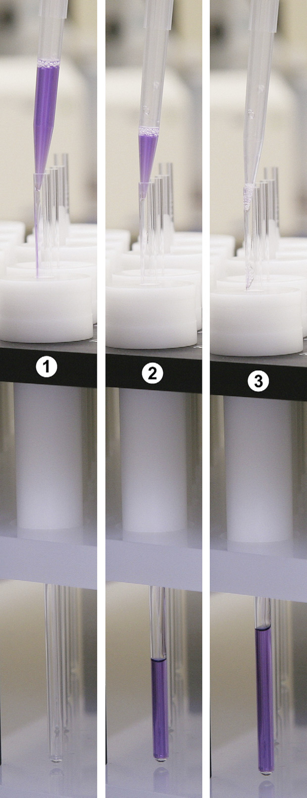
Representation of the angled incremental delivery technique for the prevention of bubble formation. See text. 1. Initial at top of the NMR tube. Second addition in progress. 2. Liquid has descended to approximately the middle of the tube. Note that there is a continuous path from the tube top to the leading edge of the liquid. 3. Completion of the liquid path to the bottom of the tube and subsequent additional liquid drops.
Safety Enclosure—ANSI/RIA R15.06–1999
The development of any new laboratory equipment should not proceed to completion without an adequate evaluation and implementation of standard safety approaches. Our Department used the ANSI/RIA R15.06–1999 document, the safety standard for industrial robots and robot systems from the American National Standards Institute (ANSI), Washington, DC, and the Robotic Industries Association (RIA), Ann Arbor, MI.
We found this document very useful and simple to use. Following the risk assessment method, tabular forms indicating risk estimates and risk reduction determination the appropriate safeguard selection are obtained.
Safety Requirements
From the Risk Estimation tables, a Hazard Identification List for WARPA robots was obtained:
Gripper Pinch point. Trapping operator between gantry and device on table during XYZ axis movement. Rotary table, pipette, or gripper hitting operator's face (speed: 33 in./s). Crash shatters plates, glass vials, sending projectiles at relatively high speed. Crash splatters solvents, chemicals, etc.
Safety Implementation for WARPA robots
Safeguards Selection. According to the previous Hazard Identification List, a safeguarding system to provide Category R2 risk reduction (9.5.2) was needed.
A Labrepco, Inc. (101 Witmer Road, Horsham, PA) representative was brought in to discuss different enclosures and mechanisms that would fulfill safeguard area requirements as per 10.4.1. Labrepco is a company specializing in different laboratory equipment with experience in these types of enclosures. The vendor provided the safeguard systems for WARPA in about 2 months (Fig. 10).
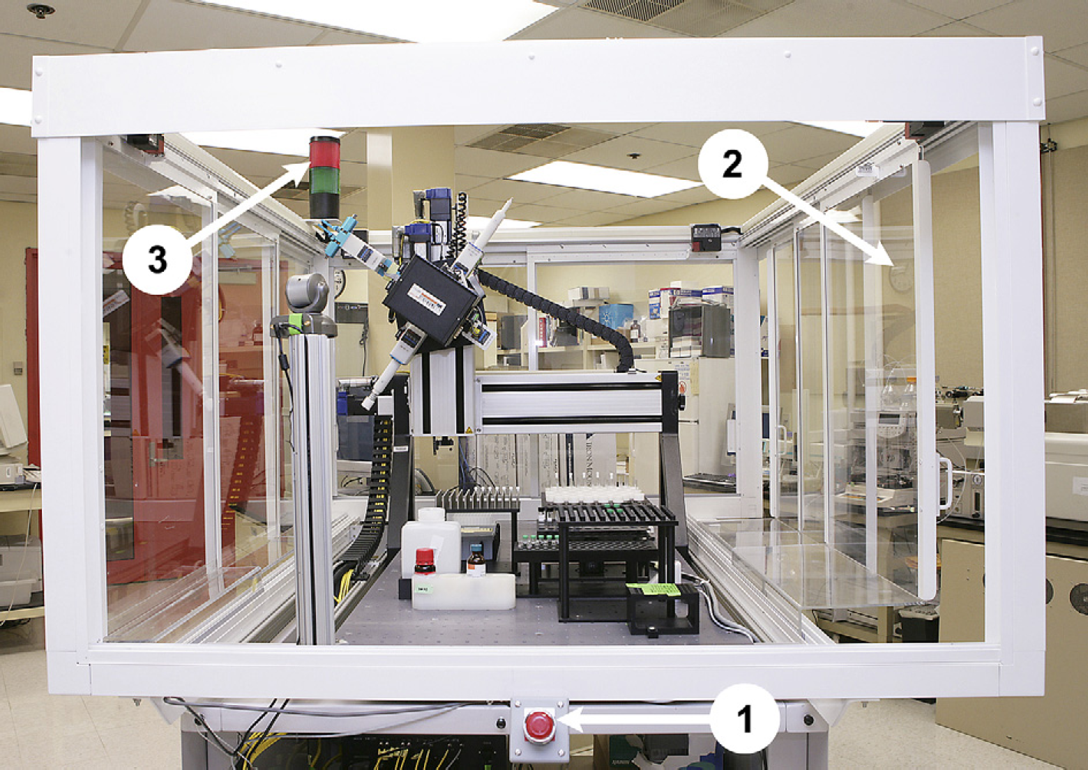
Standard WARPA safety features. 1. Emergency stop button (one of four). 2. Safety enclosure with interleaved trilevel doors on the sides for easy access. 3. Warning light. Not shown—Standard robot warning signage.
Control Software
The system uses Genera/Supra/DataPilot commercial software from Retisoft to provide the scheduling and control functions. The Genera framework is developed using an object-oriented design, the software is built upon an open and extensible architecture that allows the developer to control and monitor any instrument. The Supra application provides time-based schedule optimization and uses a java-like scheduling language. The DataPilot is a web-based application that runs on top of Genera framework. These products were selected for their cost, ease of integration, hardware-platform independence, and portability. To bridge the above framework to our legacy ActiveX tool, gantry, and instrument drivers our department uses on different automation platforms, we used the J-Integra 2.1 Java-to-COM software from Intrisync Software Intl., Inc., 11130 NE 33rd Place STE 200, Bellevue, WA, 98004.
User Interface
The WARPA robot software allows flexible user control and monitoring. Through a series of interactive web pages and hardware control buttons, the robot operator is provided with succinct and clear assay information, data entry functions, and robot workspace access.
As indicated above, the login of the samples is performed at the start of the run. Included as part of the login method is a barcode scan wand to scan the sample management data sheet of each incoming sample. The software user interface also provides a means to enter the sample ID manually in case barcode labels have been damaged or are missing (Fig. 11).
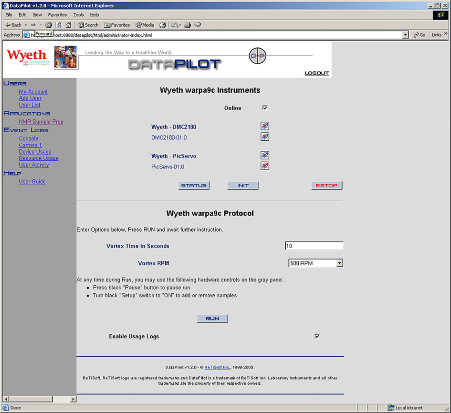
Graphical user interface.
The Genera framework maintains log files displayed in real time of the command communications between the control program and the different hardware associated.
At the end of the run, output text files and final instructions request the operator to add more samples and continue or simply terminate the run and save the data file for the completed rack of samples.
One advantage of using the Retisoft products is their ability to communicate between the user and robot using the HTTP protocol. Our group disables those features which permit hardware operation from a remote location to the laboratory where the robot is operating, but it is a clear advantage to have access to all the other functions, such as monitoring the console output, the command communications log and the camera live video, and device and resource usage. The camera is a DCS-5300G unit from D-Link (1.800.326.1688 or
Accessing the console link, a view of the output messages is available. These messages and their content is defined in the control program providing a useful tool for debugging as well as monitoring the activities of the system in real time.
Software Design
Using the J-Integra Java-to-COM software allowed us to integrate a series of ActiveX tool control applications that had been developed earlier and implemented in a non-Retisoft environment—even Excel (Fig. 12). Recycling these components reduced significantly our turn around time for complete systems and added portability between different hardware platforms.
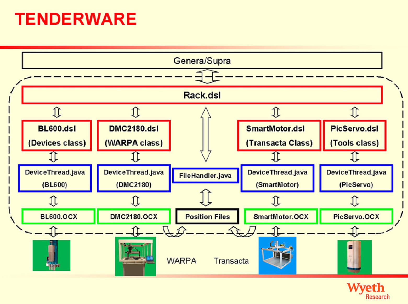
Layered Control and Criver Crchitecture.
This framework allows the development of automation platform–independent “middleware” for schedule and assay portability. The resulting software is used throughout different automation platforms with distinctive sets of tools whereas the high-level programs are fully ported between systems.
On the top or high-level language layer, a java-like language, following object-oriented programming (OOP) rules and providing extensibility and method overloading, enables the programmer to quickly develop complex robotic manipulations and simplifies documentation by the use of automated document generation, part of the commercial software from Retisoft.
Most objects in our “middleware” layer belong to a large class named Rack. That is, the objects this robot executes methods to are “Rack” objects. Aspirate, dispense, moveTowards(), or MoveAway() are methods used most often. Typical operations follow the “object.method” construct, for instance, deepWellPlate. dispense(10.0) would dispense 10 μl into the object deepWellPlate. Further details about OOP are beyond the scope of this paper and we invite the reader to consult specific bibliography about the matter. We believe that the human ability to handle and understand objects is one reason behind object-oriented programming. One can then say, writing or developing control programs using a programming language that follows object-oriented rules is very intuitive and thus clear and simple.
The foundation on which the top and middle layers rest are a series of ActiveX control applications. These applications execute the specific commands and monitor activities to the varied tools and gantries used. These custom ActiveX controls are responsible for keeping the entire low-level status variables and methods necessary for proper functioning of these complex devices. Figure 13 depicts the user interface for one of them, a control for the motors of a four-axis gantry robot platform.
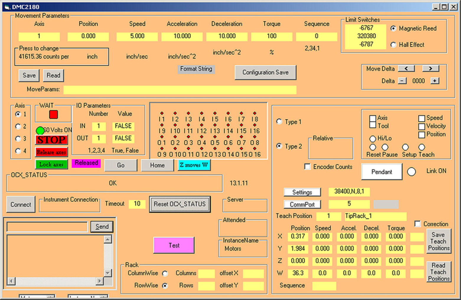
DMC2180 ActiveX gantry control.
Rent-A-Robot
Although these robot development efforts usually result in an automation system, which satisfies the researcher's needs, those needs change with remarkable speed. Even the best of robots can be found collecting dust in some forgotten corner of a laboratory because its original requirements have been superseded and new automation has replaced it. We have developed a line of small portable robots which can be developed for specific requirements and then, when needs change, returned to our building for renovation and redeployment to some other lab for a new life. To make it all happen though, the researcher needs some sort of incentive to return the robot once it is no longer needed. To accomplish this, we have developed a “rent-a-robot” concept where a monthly fee is charged for the possession and maintenance of each of our robots. Ownership is not transferred to the researcher except for unique add-on devices such as plate washers and analytical balances.
Determination of the appropriate monthly fee involves a decision about the lifetime of the platform and each device, as well as the maintenance costs of each component. Most of these values are estimates only because a determination of the actual values would be complicated by the ability to move the devices from robot to robot even during the useful life of the robot.
TransActa Robot
In addition to the WARPA line of robots described above, a new generation of low-power, lightweight, portable, and expandable platforms have been developed by our group (Fig. 14). For these robots (named TransActa), a modular approach extends to the overall system. The ease of manufacture and the ability to integrate the modules in the controlling software allows for the expansion of systems by simply linking the modules together physically and in software. Because each module is a fully functional entity, throughput is dramatically improved. This system-level building block approach is used in conjunction with the Rent-a-robot concept for robot recycling. The latter, represents a substantial overall savings to research groups and is based on the highly flexible and reconfigurable robot and tool architecture used. With a few keystrokes, the designer can reconfigure the hardware platform and adapt the software control program to exercise a variety of very different automation platforms.
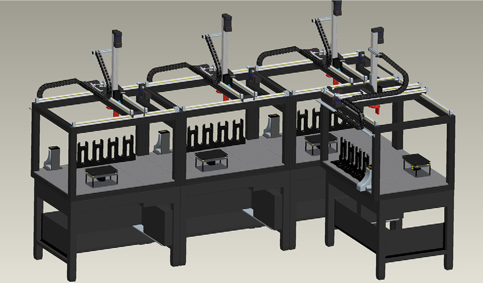
Mockup of a quad-module implementation of the TransActa series of robots. See text.
Conclusions
A systematic approach to the efficient design of laboratory robots is described here. The use of modularity in the both software and hardware has resulted in robots that are easy to fabricate, modify, and deploy and meet the needs of the scientists. Operator safety is integrated at an early point in the design of both the overall system and the individual devices. A design of a small robot using these concepts and the implementation of a robot recycling strategy has resulted in the efficient use of the groups' time and development expertise.
Acknowledgments
The development and fabrication of the WARPA and TransActa Robots required a high level of collaboration between different groups across our company. We want to thank Lenny Candela, Frank Lambert, Lynne Miller, Marc Papi, Joe Boulay, Heinz Molitor, Len Brigman, Anton Federkiewicz, Doug Whitstone, and Kevin Mullen, from Biomedical Engineering. We also thank our customers for whom these units were developed, Dr. Frank Koehn, Dr. Al. Bach, Dr. Vasilios Marathias, Jim Mattes, and Diane Andreka.