
Abstract
Commercially available preparative liquid chromatograph/mass spectrometer (LC/MS) systems are commonly used in drug discovery research to purify large numbers of compounds made by parallel synthesis techniques. The systems in our lab are comprised of individual instruments that communicate continuously with control software in order to collect specific compounds based on mass triggering. Over time, communication errors may cause improper system operation, and excessive pressure during injection may cause system damage or a leak. The risks of sample loss and safety hazards precluded unattended overnight operation of the purification systems.
A stand-alone monitoring system was developed to ensure proper purification system operation. Custom sensors and software are used to identify failures and remotely control power to the purification system. In response to a failure, the monitoring system will either shut down the purification system or, if possible, selectively reboot an instrument to allow continued operation. With the creation of the monitoring system, the purification system can be run unattended with
Introduction
Advances in the automation of parallel synthesis methodology 1 have given researchers the ability to produce thousands of new chemical entities in a relatively short period of time. High-throughput synthesis has been especially favored in the pharmaceutical industry, where large numbers of new candidate molecules feed into the early stages of the drug discovery pipeline. These new molecules are usually screened for biological activity using high-throughput screening techniques as the first stage in identifying a new drug candidate.
In order for biological assays to provide meaningful and reliable information, the molecules that are screened must be relatively pure and free from substances known to affect assay results. High-speed synthesis and screening operations demand highspeed purification techniques. Several groups 2 –8 have developed purification systems in-house or have modified existing systems to address the very large number of molecules derived from parallel synthesis. Automated high-throughput purification systems are now available from several vendors. 9 –13 These systems frequently employ reversed phase liquid chromatography in order to cover the vast molecular property space of the solutes of interest as well as all other components in diverse reaction mixtures. Fraction collectors on these systems are usually triggered by a UV/visible detector and/or a mass spectrometer signal.
In our lab, tens of thousands of molecules have been purified using commercially designed purification systems. The systems use preparative-scale high performance liquid chromatography (HPLC) to separate reaction mixtures while a mass spectrometer constantly monitors the column effluent. When the mass of the synthesized molecule is detected, the system's control software triggers fraction collection into test tubes. All other components of the original reaction mixture flow to waste. The design of our purification systems is shown in Figure 1. This design is typical for preparative LC/MS systems from several vendors. The entire system (except the at-column dilution and makeup pumps) is operated by vendor software running on the control computer.

Design of the automated preparative LC/MS purification system.
While the advantages of using an automated purification system are considerable, the complexity of such a system may lead to various operational problems. Several common failure modes in the operation of our purification systems were identified. The most common type of failure is a loss of communication between the vendor-supplied control software and one of the instruments in the system. The system is composed of instruments from different manufacturers, and the control software must communicate with all of them continuously and at precise times. In addition, the system must constantly make fraction collection decisions based on a stream of data from the mass spectrometer. Over time, a large amount of computer activity may lead to a loss of communication with one or more instruments. One commonly encountered failure results in sluggish control of the fraction collector, which leads to late collection triggering. Another type of failure is loss of communication between the computer and the HPLC pump. The most reliable way to clear these errors is to reboot some or all of the instruments in the system.
In addition to possible communication errors, the risk of plugging a piece of tubing or an HPLC column by injecting very concentrated samples on a system operating with a preparative-scale flow over 16 hours (a standard overnight run) is not trivial. The problem is compounded by our use of the at-column dilution technique for sample injections. We have observed the advantages of using this technique as discussed by Blom. 14 However, the plumbing configuration may create precipitating conditions at the mixing tee before the column. As with most commercial HPLC software, the vendor's control software has the ability to stop a run if a preset high or low pressure is exceeded. Our at-column dilution pump is not controlled by the software, and during a communication-intensive run, the software may be slightly delayed in responding to a pressure problem. In less than a second, the column and other components may be exposed to exceedingly high pressures that may cause damage or a large leak. Any major leak runs the risk of exposing lab personnel and equipment to chemicals with unknown hazardous properties. It is clear that operating a high-throughput purification system may involve liabilities in addition to the aforementioned communication errors.
In order to allow safe unattended operation of our purification systems, a stand-alone system dubbed the Purification System Monitor (PSM) was developed. PSM includes custom software, sensors, and control devices to ensure proper operation of the purification system. If an error is detected in the purification system's operation, PSM shuts the entire system down to prevent loss of samples or other risks associated with erroneous system control. In one particular mode of failure, PSM is able to selectively reboot an instrument to clear an error and allow the purification run to continue successfully.
The monitoring system operates on the premise that the instruments comprising a purification system will behave in a predictable manner over the course of many sequential sample injections. This behavior can be verified by software designed to monitor a network of sensors attached to the instruments. In order to maximize the reliability of the monitoring system, the software runs on a computer that is not otherwise connected to the purification system. A set of controls is operated by the software so that instruments can be shut down or rebooted remotely if failures occur. Pump pressures are monitored to guarantee a fast response to high-or low-pressure conditions.
Purification System Monitor Design
Our monitoring system relies on the predictable, repetitive nature of events that occur during a purification run for a correct assessment of the purification system's operational status. A timeline for a typical run on a purification system is shown in Figure 2. This depiction abstracts detectable fraction collector events from the many operations of a purification system and relates them to the progress of a run. The fraction collector events trigger sensing devices in order for the monitoring system to track run progress according to the steps in the script table.

Timeline for a sample run with corresponding fraction collector events. Script steps show the events that PSM monitors in each phase of the run.
The fraction collector events are detected by two sensors: an arm position sensor and a diverter valve position sensor. Both sensors produce binary (on/off) responses. More specifically, the arm position sensor gives an “on” response when the fraction collector arm is at the rinse station, and the valve sensor gives an “on” response when the diverter valve is in the collection mode.
The PSM software is coded with the script in Figure 2 and waits for each event to be detected. The amount of time to wait may be changed by the user for flexibility with different run conditions. If the allowed time expires before an expected event occurs, the software concludes that a failure has occurred.
For most failures, a shutdown of the purification system is the prescribed response of the monitoring system. Shutdowns involve removing line power to the injector and triggering the stop-flow inputs built into the two HPLC pumps and the makeup pump. The stop-flow signals are all held indefinitely after a shutdown. Power to the injector is removed for only one minute before being restored; experience has shown this time to be sufficient for the control software to detect a fault and stop making injections (i.e., the injection queue is paused). After a shutdown, the purification system may not be started again until a user releases the pump stop-flow signals in the PSM software.
It is possible to continue a run in the case of one type of error: a delay in the opening of the diverter valve with the arm at the rinse station between runs. This is the most frequent error we encountered with our purification systems. The problem is related to communication demands on the control computer. Our original system configuration included a UV/visible detector plumbed in parallel with the mass spectrometer. When we reduced the data collection rate of the UV/visible detector (and eventually removed the detector from the system completely), the frequency of the valve control error was greatly reduced. However, since the error has not been completely eliminated, it is a liability for long periods of instrument use because it leads to incorrect timing of subsequent fraction collections and lost samples.
Experimentation showed that when this error appeared during a run, a manual reboot of the fraction collector would clear the error and allow the purification run to continue. Therefore, reboot functionality was built into the PSM software. When the arm reaches the rinse station between injections and the valve does not open within the specified time (usually three seconds), the PSM software removes line power from the fraction collector, restores it a few seconds later, and homes the arm by simulating the depression of the “Start” button on the front panel via a wire tap inside the instrument. 15 Communications with the software are not disturbed during this process, and the fraction collector continues to operate normally afterward.
The collection of circuits that comprise the PSM sensing and control functionality are shown in Figure 3. Sensors and control circuits were built in-house using common electronic components obtained from RadioShack (Fort Worth, TX) and Newark InOne (Chicago, IL). All of the input and output operations are conducted through a DAQPad-6507 digital I/O card from National Instruments (Austin, TX). An additional function that is controlled by PSM through this card is the ability to switch mobile phase source valves after a preset time elapses. This functionality became vestigial when we replaced the solvent reservoirs on our systems with larger reservoirs that could handle overnight runs. Nevertheless, the primitive operability of a timed digital switching signal was retained in PSM for unforeseen needs in the future.

PSM software resides on a stand-alone computer and communicates with two sensors and six control circuits through a digital I/O card. Control circuits for switching mobile phase source valves were removed and are not shown.
The pressures of the gradient and at-column dilution pumps are monitored continuously via the pressure output connections on the back of the pumps. These signals are fed to the analog-to-digital inputs of a Gilson (Middleton, WI) 506C system interface card. Since pressure monitoring was added well after the PSM software was originally written, a separate module is used for this function. All software was written in-house in the C++ programming language (Borland Software Corp., Scotts Valley, CA).
PSM Software
The Purification System Monitor software is a single-form Windows application. As shown in Figure 4, the form is divided into seven main sections based on functionality. The application uses a timer method to coordinate all input and output activities with sensors and control circuits. The timer interval is set in section A and is usually several hundred milliseconds. This section also contains buttons to start or stop communications with the digital I/O card (“Monitor Purification System”) and to begin or end monitoring a purification run using the preset script (“Execute Script Control”).

The main sections of the PSM software window are application controls (A); arm position and valve status indicators (B); time controls (C); current script step indicators (D); manual shutdown, reboot, and mobile phase valve controls (E); script contents (F); and fraction and sample progress counters (G).
When script control is selected, a continuous loop through the steps in section F is started. These steps match the fraction collector events shown in Figure 2. The first three time values in section C correspond to steps 2, 3, and 4 in the script, respectively. If a script event does not occur in the set amount of time, a shutdown or reboot will occur as previously described. Otherwise, PSM will continue to step through the script in loops—one loop per injection—until an error occurs or a user stops the script manually. A sequence of injections that terminates without fault will simulate an error at the end of the run when the fraction collector stops operating. The concomitant shutdown is beneficial because it stops all pumps, including the uncontrolled at-column dilution and makeup pumps.
The remaining controls in section C of Figure 4 are used to set times and to activate countdowns for the mobile phase source valves (or other timed events). Section D shows the script steps as a run progresses, and Section E provides status indicators and manual overrides for the control circuits. The fraction counter in section G is initially set by the user and automatically increments during a run when diverter valve activity is recorded with the arm away from the rinse station (i.e., at a test tube). The fraction number and all other monitoring system events are recorded in a log file that is useful for diagnosing purification system failures. The sample counter in section G is similar to the fraction counter in operation, using the “arm at rinse station” event (script step 2) to trigger a counter increment. Its value is recorded for use with the remote status software (vide infra).
Pressure Software Module
A separate application (Figure 5) was developed to record the pressures from the gradient and at-column dilution pumps and to signal the PSM software to shut down the purification system if a high- or low-pressure limit was exceeded. Pressures are displayed in real time for the user and are recorded in a log file for later review. Each pump may have different pressure limits, and the highest and lowest pressures observed while monitoring are displayed for each pump.

The pressure module in the monitoring system ensures that both the gradient and at-column dilution pump pressures do not exceed specified limits.
A button at the bottom of the form is used to enable communications with PSM software. The pressure program writes to a status file that PSM reads with every iteration of its own timer function (several times per second). A shut down can be initiated in less than one second if a pressure problem occurs.
Sensors
Sensors were installed on the fraction collector to detect whether the arm is at the rinse station and the diverter valve's position. The arm position sensor consists of magnetic bars situated on the X- and Z-arms and magnetic switches attached to the Y-arm (Figure 6). The switches close when they are proximal to the magnets (i.e., the arm is at the rinse station). When they close, continuity between a 5-volt power supply attached to one switch and a signal wire attached to the other is achieved. The signal is picked up by PSM through the digital I/O card.

The arm position sensor components are situated on the fraction collector. As shown here, the arm is at the rinse station, and the magnetic switches will be closed to transmit the 5-volt signal to PSM.
The diverter valve is activated when the control software commands one of the relays on the back of the fraction collector to be closed. This relay is connected to the native 24-volt power supply on the instrument. The voltage to operate the valve is much higher than PSM's digital card can accept as a signal; therefore, a circuit was designed to transmit the valve signal to the card. A transistor and a 5-volt relay are used to minimize the current drawn from the valve signal and to isolate the digital signal from the valve power supply (Figure 7). A voltage divider circuit sends a 5-volt signal to the digital card and a 0.5-volt signal to an analog input on the back of the mass spectrometer (valve operations are thus recorded in synchronization with chromatographic data).

PSM's valve position circuit is built around the original fraction collector connections.
Control Circuits
PSM's control operations mainly consist of relay closures that stop purification instruments from running. As with the valve position sensor, transistor circuits were designed to minimize the current drawn from the digital card and to provide isolation between the card and the rest of the circuit. The relay circuit design for the gradient, at-column dilution, and makeup pumps is shown in Figure 8. The pumps stop when the contacts on the back of the pumps are closed.

Relay circuit designed to stop the gradient, at-column dilution, and makeup pumps.
The circuit design above is also used for triggering 12-volt power relays to shut down the injector and fraction collector (Figure 9). The power cords for the instruments are substituted with cords that are connected through the circuits. Push-button switches are attached to allow manual activation of the relays. This convenience allows us to reboot the instruments without reaching behind them (often over a full bed of samples or fractions).

Power relay circuit designed to remove power from the injector and fraction collector.
In order for a rebooted fraction collector to resume operations, the “Start” button on the front of the instrument must be pressed. A cable runs from the instrument's front panel to the motherboard. Within this cable, the wires that are connected to the button were identified. They were isolated, stripped, and connected to another relay configured as in Figure 8. The button can therefore be “pressed” manually or through the PSM software.
Remote Status Software
The ability to run purification systems unattended motivated the creation of software to monitor their progress remotely. Since the stand-alone PSM computers are connected to our organization's intranet, an obvious solution is to read the status directly from the computer's hard disk drive. PSM writes the system's operational status and current injection to a local file. Remote status software (“PSStat”) runs on a separate computer and actively retrieves status information from the PSM computers. Any user with intranet access (including access from home) can determine if the purification systems are active. PSStat creates an icon in the Taskbar Notification Area (System Tray) in Windows. A timer function is used to retrieve system status continuously. When the status changes, the color of the icon changes (Figure 10a c). Moving the mouse over the icon shows the identity of the system being monitored and the current injection.
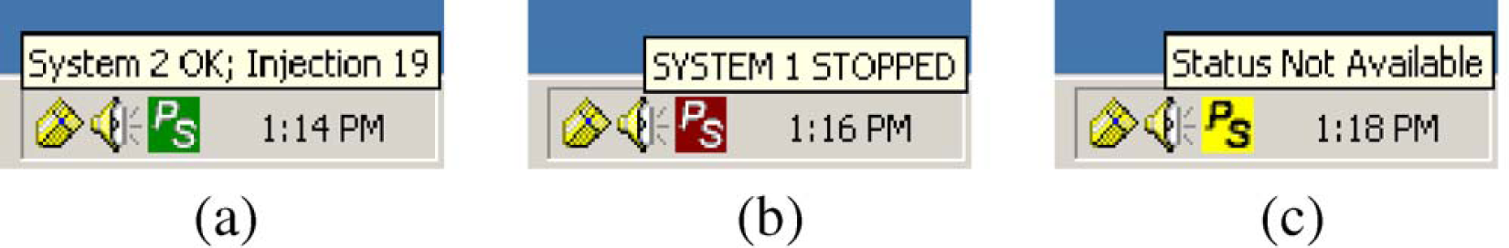
Purification system remote status (PSStat) software. The operational status of a purification system is represented by the color of a notification area icon. Green is operational (a), red is stopped (b), and yellow is unknown (c).
Results
Nearly 40,000 injections have been made to date with PSM in place. Overnight, unattended runs of the purification systems have become routine, and we are confident in PSM's ability to stop the runs if dictated by erroneous system operations. The ability to reliably run purification systems frees lab personnel to do other work.
Communication errors are the most common failure mode of the purification systems. The PSM log file shows that fraction collector communication errors still occur occasionally. The PSM-generated fraction collector reboot continues to solve the problem, and it increases the likelihood that a purification system will operate all the way through the night. With other types of communication errors, PSM has prevented mishaps by shutting down the purification system. For example, we have seen several instances of a communications failure between the control computer and the gradient pump. The control software paused the injection queue in these cases, but it could not stop the pump from running at whatever its last composition happened to be before the failure (usually the starting composition for our reversed phase gradient). PSM stopped the pump in these cases because the fraction collector events were not occurring. If not for this termination of operation, the pump would have run the aqueous reservoir dry, causing pump damage with a high preparative flow setting. For communication errors, fraction collector event monitoring has proven to be highly effective for ensuring proper system operations.
The supplemental pressure module has been invaluable for preventing leaks and other safety hazards that usually result from clogged components in the flow path. In addition to its designed use, the pressure module also helps us to diagnose problems with our injection scheme when high-pressure limits are exceeded. By reviewing the pressure log records preceding a shutdown, we can determine which part of the flow path is clogged. If both pump pressures rise before shutdown, the blockage has occurred within or after the at-column dilution mixing tee. If only the at-column dilution pump pressure rises, the blockage has occurred in the injector or its connection to the mixing tee. This method of diagnosis provides insight into the likely cause of the blockage: improper at-column dilution conditions in the former case and the presence of sample precipitates in the latter. Methods for avoiding both of these problems are currently under investigation in our lab.
Discussion
Automated purification systems with mass-directed fraction collection require robust instrument control software for long injection sequences. The software must not only control instruments for normal operations, but it must also recognize and react to endogenous and exogenous error conditions in a timely fashion. A “clean” reaction to an error, such as a complete shutdown or an instrument reboot, must be absolutely guaranteed if a purification system is to be left unattended for a long period of time; the preciousness of the samples and the threat of safety hazards leave little room for unpredictable behavior. We found that the vendor-supplied software for our purification systems did not have sufficient safeguards to meet our needs for overnight runs.
Few commercial software packages (for instrument control or otherwise) meet all of the specifications of the end user. There are three common ways to address defects or insufficient features of a commercial software package. The first is to participate in a software revision plan with the software designer. This approach has the advantage of requiring less technical expertise (i.e., software engineering) on the part of the customer, but it may ultimately cost more time for multiple revisions—especially if all of the customer requirements are not well articulated, or even known, at the beginning of the process. This was demonstrated in our case as the pressure module was added more than a year after PSM was first implemented.
The second approach to dealing with inadequate commercial software is to supplement it with custom software that interacts with or operates through the native application (such as macros). The advantages of this approach include the speed of implementation and the modest level of programming expertise needed. However, it is rarely possible to affect changes to the core instrument control functions of software in this way; therefore, this approach was not applicable to our needs. Both of these approaches involve a strong dependence on the reliability of the commercial software.
A third approach is to avoid commercial software altogether in favor of applications developed completely in-house. The proprietary nature of instrument control software works both for and against the customer in this situation; truly unique solutions are protected from outside access, but an application programming interface (API) for an existing instrument may not be available to the customer from the manufacturer. Developing purification system control software ab initio offers the greatest flexibility for a lab, but it comes at a great cost in time and technical expertise.
With our monitoring system, we took a new approach to dealing with the shortcomings of commercial instrument control software. 16 Unlike the first two approaches, our approach does not rely on the original control software. In contrast, it relies on isolation from the control software. Our development of stand-alone monitoring software is similar to the third approach, but we do not replace the control offered by the vendor's software. Our approach required a modest investment (about three FTE months) in software design expertise and development time. In return for this investment, we have gained complete reliability of our purification systems using software that is easily customized and safely isolated from the control computer.
Automated purification systems are complex enough to benefit from stand-alone monitoring. Most analytical instrumentation is neither this complex nor prone to as many failure modes that lead to unrecoverable consequences (e.g., a failure on a typical LC/MS means the samples will be reanalyzed later). However, there are circumstances in which a stand-alone monitoring system would be useful for these simpler systems. In cases where reliability and safety are concerns for complex automated systems (or many simpler systems operating in parallel), the stand-alone monitoring concept could be applied. In addition to hardware sensors, “software sensors” can be created (e.g., the appearance of new data files on the control computer within a specified amount of time). Stand-alone monitoring and control would ensure that time and materials are not wasted when systems are not operating correctly.
Future improvements to the monitoring system may include the addition of liquid leak sensors and level sensors for the mobile phase reservoirs and waste containers. A second-generation monitoring system has also been proposed. Currently the purification system will “operate until made to stop” by the monitoring system. This paradigm is not ideal because it assumes that the purification system is operating properly and that the monitoring system can promptly respond with a shutdown in case of an error. A better way to run the purification system is to “not operate until made to start” by the monitoring system. By queuing only one sample at a time into the vendor's control software, the monitoring system has as much time as it needs to assess the operational suitability of the purification system before beginning another injection.
Conclusions
The monitoring system we developed ensures safe unattended operation of our automated purification systems, and it has greatly improved our overall productivity. The systems are prevented from operating when failures in communications or pressure problems exist, and under certain circumstances we can recover from a communications failure without interrupting a run. The ability to operate systems with complete confidence required only a modest investment in software and sensor development time.
Acknowledgments
The author wishes to thank Scott Dekart, Jon Guertin, Rick Hansen, Jill Maloney (3M Pharmaceuticals), and Sagar Kawle (Braun Intertec, Minneapolis, MN) for their assistance with constructing and verifying the operations of the monitoring system