
Abstract
We have developed proprietary technologies for executing continuous flow assays in biochips which mimic human capillaries. Such technologies are integral to the rapidly growing laboratory instrumentation sector for applications in drug discovery, biotechnology, medical diagnostics and environmental studies. A common link between all sectors is the movement toward miniaturization to increase throughput, accuracy and efficiency in the development of new drugs. The miniaturization process itself leads to a demand for new instruments and tools capable of handling microlitre quantities of biological fluids and reagents, thus, we present an instrument which is capable of doing so in the form of a microfluidic enabling platform.
Keywords
Introduction
Currently, pharmaceutical companies screen target molecules/cells against a library of compounds (potential drugs) via the successful high throughput screening (HTS) method, resulting in the elimination of the large majority of unsuitable drug candidates. However, after a successful HTS assay, a pharmaceutical company may still have many thousand possible drug candidates requiring assessment. In addition, animal trials involved in this process are often initiated too quickly and have long been the subject of criticism not only from animal rights groups but also from scientists.
The use of microfluidic devices for drug discovery, biomedical research and potential clinical applications has a number of significant advantages. Firstly, the volume of fluids within these channels is very small, usually in the microlitre range. This is especially significant for efficient utilization of costly reagents. Such devices also enable reduced analysis times and larger transfer rates due to the diminished distances involved. Additionally, in running several assays in parallel, each process in an assay can be manipulated step by step through computer control resulting in great efficiency. Again, this accuracy, in combination with higher yields, leads to a reduction in waste. This is not only more economically favourable but also environmentally beneficial where hazardous chemicals are involved. Also, in contrast to silicon micromachining, the fabrication techniques used to construct microfluidic devices are relatively inexpensive and are very amenable both to highly elaborate, multiplexed devices and also to mass production. In a manner similar to that for microelectronics, microfluidic technologies enable the fabrication of highly integrated devices for performing several different functions on the same substrate chip.
Migration of the cells of the immune system into inflammatory sites and efficient contact recognition of invading pathogens underlies host defence. Extravasation of circulating T-lymphocytes (which largely contribute to cell-mediated host immunity) into diseased organs and tissues involves sequential processes of intracapillary cell flow, rolling, firm attachment to the vascular endothelium and subsequent migration through it / or diapedesis, see Figure 1.
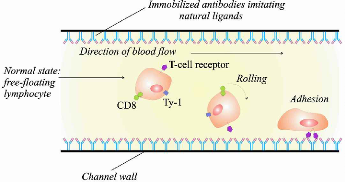
Leukocyte flow and rolling, tethering and activation, followed by firm adhesion: Extravasation of circulating T-lymphocytes (which largely contribute to cell-mediated host immunity) into diseased organs and tissues involves sequential processes of intracapillary cell flow, rolling, firm attachment to the vascular endothelium and subsequent migration through it / or diapedesis.
We describe here a miniaturised microfluidics enabling platform developed to simulate individual or combinatorial factors affecting lymphocyte behaviour in human capillaries. In contrast to conventional glass capillary flow systems our microfluidic enabling platform in combination with high-resolution digital microscopy enabled us to monitor the behaviour of single cells and to design experiments that yield a wider range of quantitative data.
An understanding of the mechanisms of lymphocyte migration is critical for development of novel strategies for the treatment of inflammatory diseases. Key factors affecting this process are blood flow parameters (blood rheology), cell receptors interaction with extracellularly presented ligands and additional stimuli of various nature including distant messengers of inflammation (i.e., chemokines and cytokines). We can model these significant events in our microfluidics enabling platform through the use of appropriate immobilised ligands (either separate or in combination) for lymphocyte surface receptors as substrate coating agents in the biochips. Also, precision regulated blood flow conditions may be achieved by altering the sheer stress coefficient in the biochip assays. In addition, inflammatory micro-environmental conditions may be simulated through the use of chemokines. Taken together this technology enables us to study living cell behaviour in a model closely related to the physiological situation in vivo.
THE MICROFLUIDIC PUMPING SYSTEM
Miniaturized sample volumes used in microfluidic biochips, precision delivering of required solutions to the sites of reaction, mixing different liquids, creating concentration gradients of the reagents, controlling the position of biological samples, transporting and manipulating them are all tasks, which require a highly accurate pumping system.
Despite a major effort in developing pumping systems for microfluidic biochip structures, many conventionally used pumping systems are still operating with significantly larger volumes of liquids and therefore cannot provide pumping accuracy or in some cases adequate pumping speed when it comes to establishing flows inside the biochip structures with microchannel diameters from 5 to 100 μm. Various constructions of positive displacement pumps, including syringe pumps, positive pressure infusion pumps and peristaltic pumps have been used with capillaries.
Syringe pumps with microflow rate capabilities to provide precise and reproducible volumetric flow ranges of the order of 0.1 μl to 1 mL/min are currently in use. One of the main objects of such pumping systems has been to deliver pulse free flow, the problem being that the pressure of the fluid inside the syringe pump changes during the stroke of the syringe pump, where the stroke is usually controlled by a stepper motor. Unfortunately, such an operation results in a large pressure surge which alters the volumetric flow rate.
As a result, such syringe and positive displacement pumps have been relatively inefficient at delivering fluid flow at rates of the order of nanolitres per minute, which is the flow rate required to transport liquids within microfluidic biochip structures. Generally, the limitation on the flow rate is the movement accuracy of the various mechanical parts of the syringe pump such as the stepper motor, plunger, valves, and so on. For commercially available syringe pumps, the linear displacement of the piston or plunger would be several micrometers per step of the motor controlling the pump. Thus, general sealing surface wear makes it impossible to achieve accuracy for shorter displacements. A further disadvantage of the syringe pump when used for pumping liquids in microchannel structures, is that it cannot deliver a sufficiently low pumping speed for many applications of the structures.
Typically, a syringe pump dispenses 0.6 μl/min for one step of the motor which then has to be delivered into a microchannel structure of a biochip possibly having a cross sectional diameter of the order of 40 μm which translates into 1.9 mm/sec through the microchannel structure which is much too fast for the observation of biological specimens, detection of proteins, single cells and the creation of low gradients of reagents, which is required in many microfluidic applications. Thus, up to the present time, positive displacements pumps and in particular, syringe pumps, while very attractive for their simplicity, have not as of yet been useful for these applications.
The microfluidic syringe pump we present as part of our microfluidic enabling platform is based on a positive displacement method with an added “micro-flow reducer” (I.P. protected) which renders it capable of handling minute volumes of sample. The pump is extremely robust and optimised to handle cell-based assays unlike other pumping systems such as capillary electrophoresis.
Our microfluidic syringe pump is directed towards providing a method for pumping liquids in microfluidic biochips which enables an accurate control of flow for flow rates ranging from 100 picolitres per minute to 10 microlitres per minute. The system is suitable for pumping both conductive and non-conductive liquids and in particular, for pumping liquids with different viscosities and liquids which contain particles with sizes comparable to the microchannel's diameter. Thus, such a pumping system is suitable for delivering liquids with biological samples and cells suspensions.
Specifications for the typical ranges of the pumping system are as follows, but are not explicitly limited to such ranges:
Small sample volumes: 5nl to 100μL
Low volumetric flow rate: 100pL/min to 10μL /min
Corresponding shear stress: 10 dynes/cm to 10 dynes/cm
Control of pumping velocity: 10μm/s to 1cm/s and direction
DEMONSTRATION OF LOW VARIABILITY IN DIMENSIONS FROM CHANNEL-TO-CHANNEL AND FROM CHIP-TO-CHIP
In general when chips are assembled problems may arise due to variations in channel dimensions. Any geometrical variations in dimensions can cause slight fluctuations of shear stresses within the channels. In general, for laminar flow, the pressure drop across a channel/capillary is proportional to the volumetric
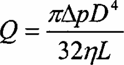
flow rate, according to Poiseuille's law. 1 For example for a circular capillary, with diameter D, length L, the volumetric flow rate adheres to the following equation:
The coefficient of proportionality consists of two terms; including the geometrical dimensions of the channel (length, L and diameter, D) and the viscosity, η, of the fluid flowing through the channel. As the viscosity of the fluid remains constant, the variation of the pressure drop across the channel, must relate to a variation in geometrical dimensions of the channel.
At present, chips are assembled manually and as such tolerances may vary slightly from channel to channel and from chip to chip. Here we carried out the following experiments to test the variations in the geometrical dimensions of the microchannels within the biochips.
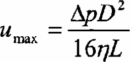
Figure 2 illustrates the experimental set-up using a calibrated capillary tube of diameter 100μm and length of 13cm and connected in series to a microfluidic channel of one of the biochips. On one end we supply a constant pressure, or base pressure, equal to 360±0.1mbar. We then measured the pressure drop of air flowing across the microchannel by a pressure gauge with precision of 0.1mbar. To apply this model, we ensured that air flow through this circuit was laminar. For this we calculated the maximum velocity of air with known pressure drop through a capillary of known dimensions, using the following formula:
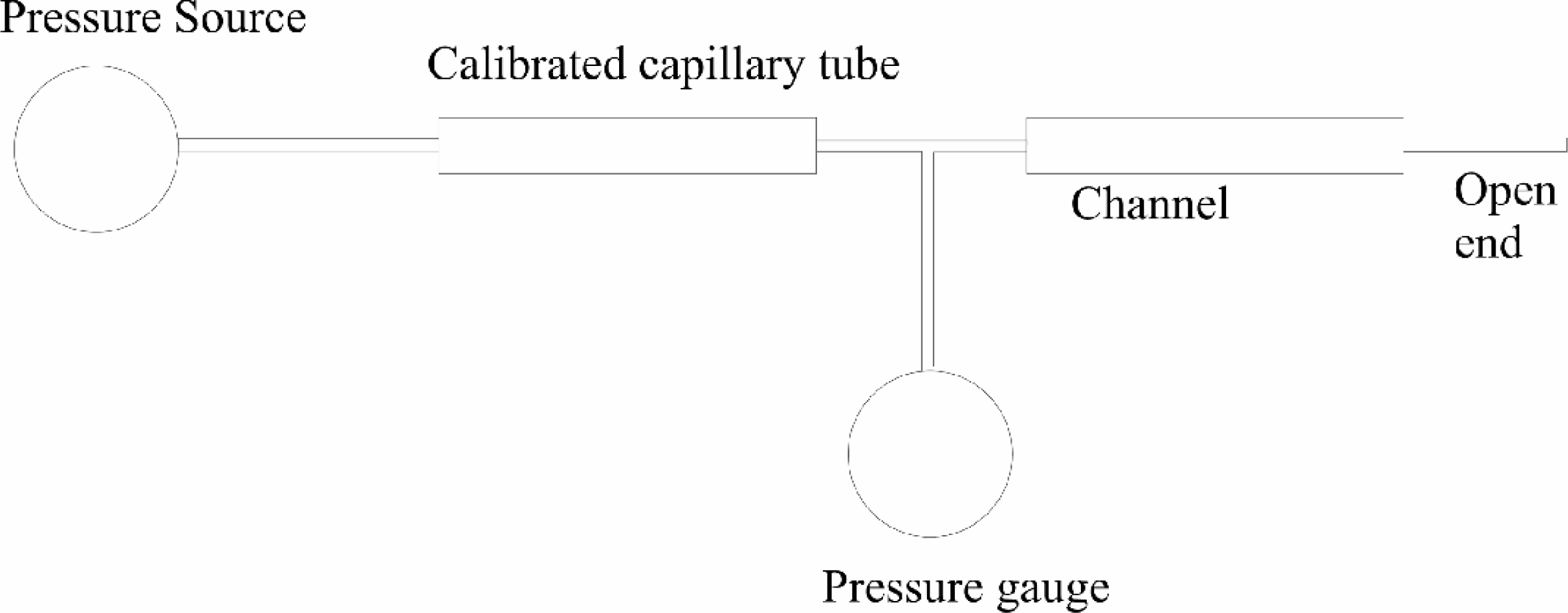
Demonstration of low variability in dimensions from channel-to-channel and from chip-to-chip: Experimental set-up using a calibrated capillary tube of diameter 100μm and length of 13cm and connected in series to a microfluidic channel of one of the biochips. On one end we supply a constant pressure, or base pressure, equal to 360±0.1mbar. We then measured the pressure drop of air flowing across the microchannel by a pressure gauge with precision of 0.1mbar.
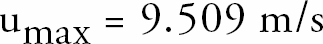
where umax is the maximum velocity of air with viscosity _, through the capillary with length L, diameter D and pressure drop, ▵ p. The viscosity of air η, is 0.0182 × 10⁻³kg/ms, the length of the capillary, L, used for calibration was 100μm, with a diameter D of 13cm and the base pressure, ▵ p, was 360mbar. This gives the following result for the maximum velocity of air through the capillary:
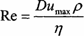
From this, we calculated the Reynolds number using the equation below determining the type of fluid flow within the capillary:
where the density of air, ρ, is 1.156 kg/m 3 . This gave the following result:

Since the Reynolds number was far less than 2300, we concluded that the air flow through the capillary was in fact laminar. By measuring the pressure drop across each individual channel and from chip to chip, we were able to calculate the mean and standard deviation in the pressure drop from channel to channel and from chip to chip. Because the pressure drop is linearly proportional to the volumetric flow rate, we thereby illustrated the channel-to-channel and chip-to-chip variability.
Figure 3 shows a comparison of four different chips, demonstrating that in this chart the standard deviation from channel to channel is less than 8.5%. This essentially means that there will be a standard deviation of said amount in flow rate and hence smoothness of flow from channel to channel and from chip to chip.
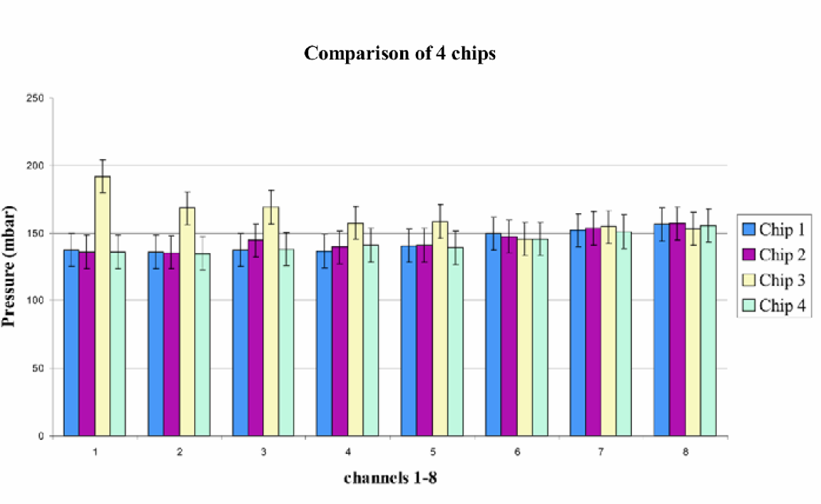
Comparison of pressure drop in microchannels of 4 different chips: Here, the standard deviation from channel to channel in pressure drop, across 4 different chips is less than 8.5%.
Materials and Methods
CELL TYPES TESTED
Several cell samples/types were tested using our microfluidic platform. Such cell types included normal peripheral blood lymphocytes (PBLs) and neutrophils isolated from the blood of healthy human volunteers and cells of HUT-78 T-lymphoma cell line (ATCC - American Type Culture Collection, Manassas, VA). Cell viability was evaluated by staining the cells with standard 0.1% mixture of Ethidium Bromide and Acridine Orange stain (live cells fluoresce green) after a minimum of 18 hours incubation on the tested surfaces in the conventional incubator conditions (semi-humidified atmosphere, 5% CO2). The tested surfaces were considered biocompatible if after the indicated incubation period cell viability exceeded 95%. Tests have been performed a minimum of 3 times with consistent results.
ISOLATION OF CELL TYPES
Isolation of PBLs and lymphocytes was performed by conventional established methods. In brief, mononuclear cells were collected as an interphase ring from the heparinized whole blood after density centrifugation at 400g for 45 minutes at 4°C over the Lymphoprep solution (Density: 1.077 g/ml, NYCOMED PHARMA AS, Oslo, Norway). Subsequently the cell population was enriched in lymphocytes by depletion of adherent cells from the cell suspension (30 minutes incubation in polystyrene tissue culture flasks at 37°C).
Isolation of neutrophils was achieved by sedimentation of heparinized blood mixed 4:1 with a solution of 6% Dextran for 45 minutes at 37°C. Following this step, the leukocyte rich plasma was collected, layered onto Lymphoprep (density gradient 1.077g/ml) and centrifuged at 400g for 30 minutes at 4°C. The resulting supernatant was discarded and the neutrophil pellet was washed twice with phosphate buffered saline (PBS). The remaining red blood cells were lysed by adding 3mls distilled water to the neutrophil pellet and vortexing for 15 seconds. Original osmotic balance was then immediately restored by addition of 1ml of 3.6% NaCl.
CHEMICALS AND PROTEINS
Ligand coatings that have been used included human recombinant VCAM-1 and ICAM-1 proteins (R&D Systems) which are expressed in vivo on the inflamed endothelium, fibronectin (Sigma) and purified bovine serum albumin (BSA, Sigma) as control protein. In some experiments, fluorescently labelled proteins and ligands, i.e. tetramethylrhodamine isothiocyanate (TRITC) or fluorescein isothiocyanate (FITC)- conjugates were utilized to study ligand coating efficiency or for cell visualization.
Phosphate-buffered saline (PBS), pH 7.4 (Sigma) was used as protein solubilization and channel washing liquid in all the studies.
VIDEO RECORDING AND IMAGE CAPTURE
A Nikon Eclipse TE300 inverted microscope with Mitsubishi time-lapse videorecorder (HS-7424) and JVC TK-C1380 colour video camera was used for image acquisition and phase contrast observations. Still microscopic images, including fluorescent, were obtained using a Leica DC-100 colour digital camera.
Experimental
Due to the flexibility of procedures such as photolithography and hot embossing, it enabled us to work with a variety of different biochip configurations. One such configuration is a simple long channel, with input and output ports, as illustrated in Figure 4.
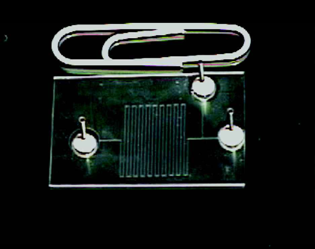
1-channel microfluidic biochip: Due to the flexibility of procedures such as photolithography and hot embossing, it enabled us to work with a variety of different biochip configurations. This is one such configuration: a simple long channel, with input and output ports.
Different coatings were experimented with in order to characterize T-cell behavior under the continuous flow regime: (i) 5% BSA as control coating (ii) ICAM, (iii) VCAM (ligands which are highly expressed on the surface of endothelial cells in inflamed capillaries) (iv) primary protein, rabbit-anti-mouse IgG with a secondary protein, the antibody to LFA-1; (v) the extracellular multiadhesive protein fibronectin.
Fig. 5 demonstrates the fold induction in adhesion seen when HUT-78 cells are observed under continuous flow on immobilised ligands. Each experiment was run with a sample volume of 2μL and a cell concentration of 2 × 10 6 cells/mL; therefore the total number of cell injected through the system was 4,000. All experiments were executed using the afore-mentioned microfluidic pumping system and at a constant velocity. Such soluble ligands are directed against T cell integrins that are known to mediate locomotion. Our results demonstrate that both ICAM and VCAM ligands stimulate firm adhesion under wall sheer stress of 1 dyne/cm 2 .
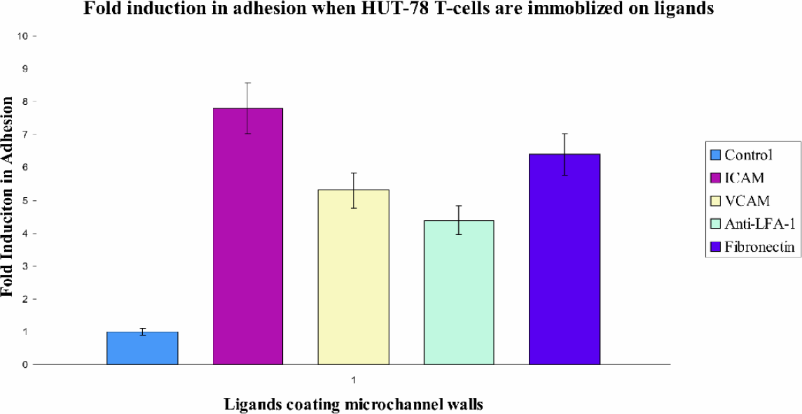
Immobilised ICAM and VCAM ligands, anti-LFA-1 and fibronectin trigger adhesion of HUT 78 T cells under continuous flow conditions. Flow channels were coated with the above ligands at 10μg/ml concentration overnight at 4 °C. Prior to experimentation channels were washed with HBSS. Cells were then infused under sheer stress of 1 dynes/cm 2 . Graph is representative of five individual experiments.
Fig. 6 (a) - (d) shows a series of sequential photographs of HUT-78 T-cells flowing through a fibronectin-coated microchannel. White arrowheads indicate the movement of the leading edge of an adhered cell while small arrows indicate cells which are flowing past, under the continuous flow regime.
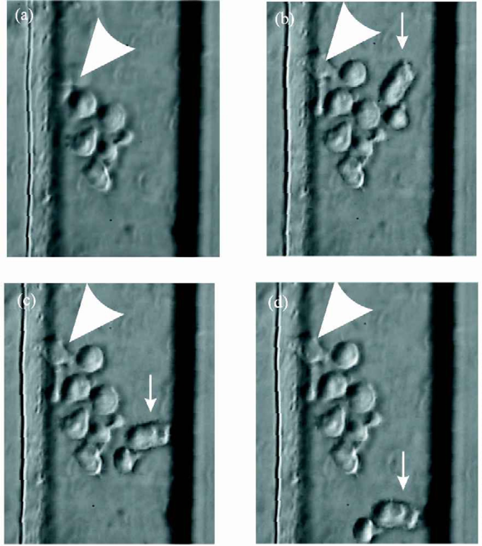
(a) - (d): HUT-78 T-cells flowing through a fibronectin-coated microchannel. White arrowheads indicate the movement of the leading edge of an adhered cell while small arrows indicate cells which are flowing past, under the continuous flow regime.
Fig. 7 (a) and (b) further illustrate the migratory behavior of T-cells in the continuous flow regime. Again, the channel was coated with fibronectin. Fig. 7 (a) was captured approximately 15 minutes after injection of T-cells. Fig. 7 (b) was captured one hour later. The exposure of the HUT-78 to fibronectin clearly resulted in spreading and dramatic cytoskeletal changes resulting in polarized phenotypes with long cytoplasmic projections. This is typical cell movement involving the formation of a leading lamella, translocation of the nucleus and extension of the trailing tail. 5
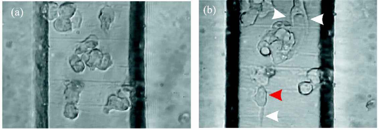
(a) - (b): Migratory behavior of T-cells in the continuous flow regime. Again, the channel was coated with fibronectin. Fig. 7 (a) was captured approximately 15 minutes after injection of HUT-78 T-cells. Fig. 7 (b) was captured 1h later. The exposure of the HUT-78 T cells to fibronectin clearly resulted in spreading and dramatic cytoskeletal changes resulting in polarized phenotypes with long cytoplasmic projections (trailing tails of motile cells). White arrowheads indicate the tails of cells while a red arrowhead indicates the leading edge of a particular cell.
One of the most important points to take into account in these experiments was the fact that the leading edges of cells were developed in the direction opposite to the flow. This leads us to the conclusion that the cells are not simply being pushed along by the flow of the oncoming cells in culture medium but are in fact migrating to areas of higher local concentration of the monoclonal antibodies.
As previously mentioned, the platform also has the potential of being used to study cell-drug interaction. This can be done in the continuous flow regime whereby the cell suspension and proposed drug candidate or chemoattractant may be injected and flow side by side without mixing. This phenomenon is known as multi-laminar flow and is illustrated in Figure 8(a) and (b) with human blood and fMLP chemoattractant in the same biochip as used to carry out the T-cell studies. In this way, a very defined and controlled gradient may be set up whereby mixing will only occur by molecular diffusion. Once the cells sense the gradient (and both this and it's concentration may be altered during an assay if required), the cells begin to migrate towards the chemoattractant, as can be seen through fluorescence detection in Figures 9(a) and (b), where FITC stained neutrophils migrate toward the TRITC labelled fMLP chemoattractant (chemotactic movement).
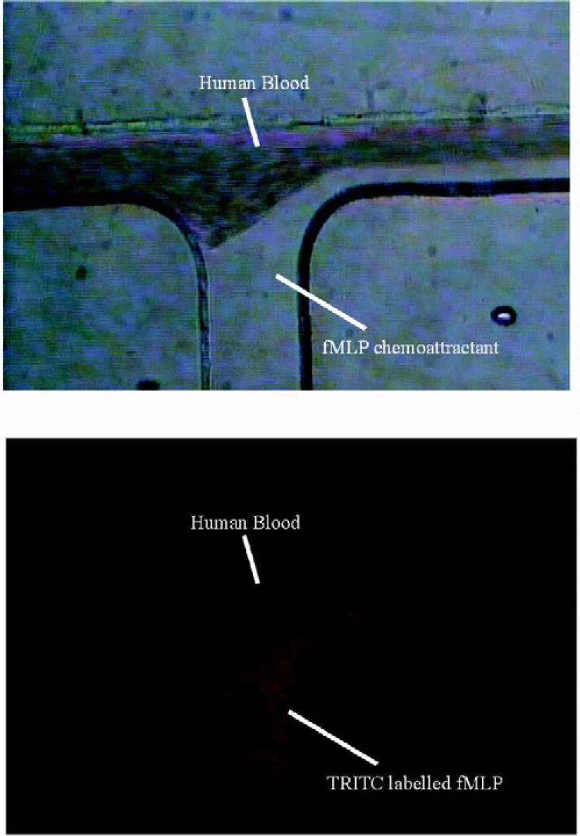
(a) - (b): Multilaminar flow of whole human blood and fMLP chemoattractant: Fig. 8 (b) illustrates same said multilaminar flow where fMLP chemoattractant is labelled with TRITC. The cell suspension (in this case whole blood) and proposed drug candidate or chemoattractant (e.g. fMLP) may be injected and flow side by side without mixing. This phenomenon is known as multi-laminar flow and in this way, a very defined and controlled gradient may be set up whereby mixing will only occur by molecular diffusion.
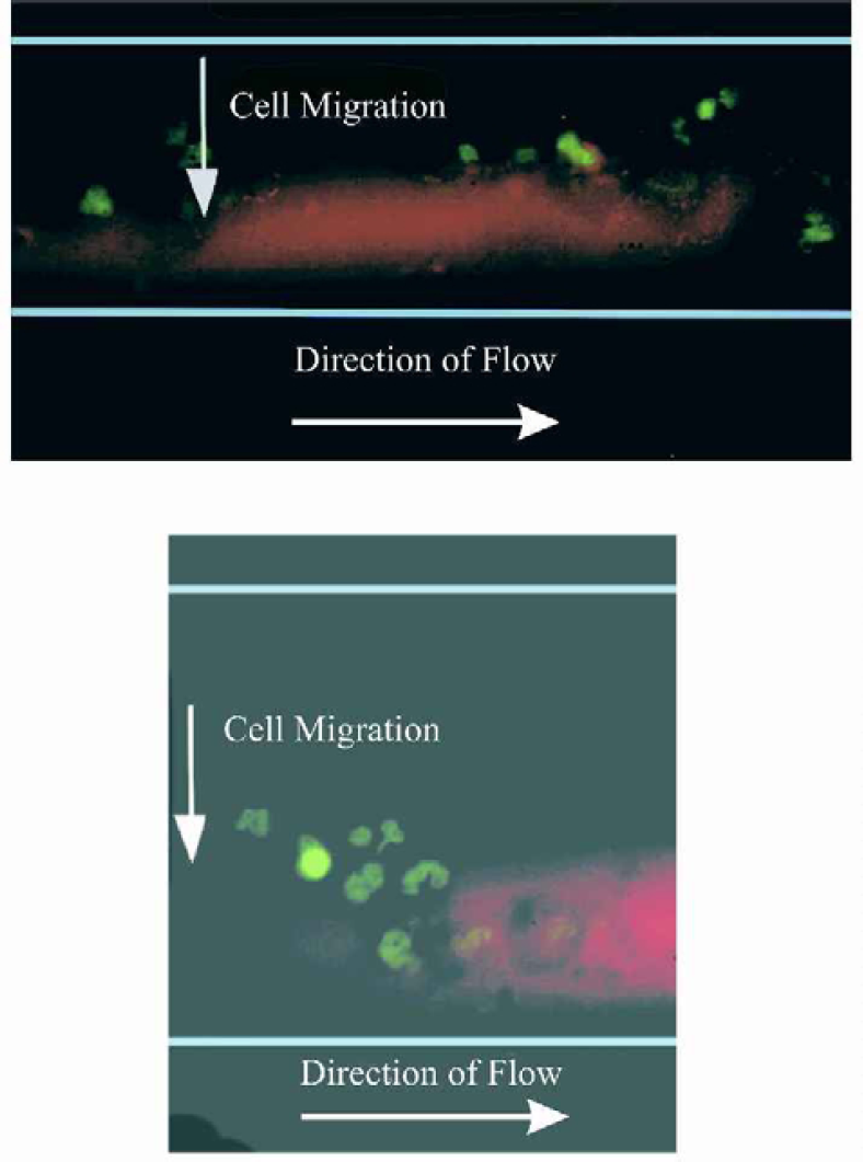
(a) - (b): Migration of green fluorescent stained neutrophils toward TRITC labeled fMLP chemoattractant: Once the cells sense the gradient of chemoattractant under multilaminar flow conditions, they begin to migrate towards the chemoattractant, as can be seen through fluorescence detection. This movement of cells along a concentration gradient is a response known as chemotaxis.
8 CHANNEL MICROFLUIDIC BIOCHIP
Another configuration of biochip which we are using is the 8-channel biochip. Such a system has a huge number of advantages over present continuous flow assay assemblies currently available; such as different coating of the channels with adhesions molecules; variation in shear stress; comparison of different cell lines or cell types; studies of combinations of different cell lines or cells types. Such advantages are due to the 8 channels in parallel which facilitates parallel studies.
The biochip comprises four distinct sections, described as follows and illustrated in Figure 10:
This essentially splits the flow into 8 different channels, whereby the pressure at each of the 8 outlets is approximated to that of the primary inlet of the flow-splitter.
Three rows of 8 microwells. The first row is used to contain the proteins/ligands with which each of the 8 microchannels is then coated. The second row is used for the cell suspension; which as with the proteins/ligands, is aspirated through the tubing connected to the flow-splitter and then dispensed once it is connected to the analysis section. Finally, the third row may be used to contain any chemokine (e.g., proposed drug candidate), which may be subsequently injected into the channel.
8 microchannels in parallel: This is the initial basic design, a straight channel 20mm in length, 200μm in width and 40μm in depth. However other designs may be incorporated here.
Cells from the assays may be collected in microwells at the end of the assay for any post-analysis test which may be required.
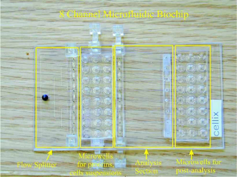
8-Channel Microfluidic Biochip: This biochip comprises 4 distinct sections for the preparation of proteins/ligands, cell suspensions; subsequent injection into the 8 parallel microfluidic channels and collection in the microwells for further analysis.
BIOCHIP CONTROL SOFTWARE
The software, illustrated in Figure 11 describes the assay protocol for the aforementioned 8-channel chip design but is not confined to such a chip as geometries may be easily altered. As can be seen from the “Biochip and pump settings” in the “MicroFlow” program, parameters of length, width and depth of the microchannel in the analysis section of the chip may be entered in order to calculate the geometry configuration. In addition, variables such as the viscosity of the medium being used or the volume of the syringe incorporated in the syringe pump (since this may be changed depending on the required volumes) may be entered.
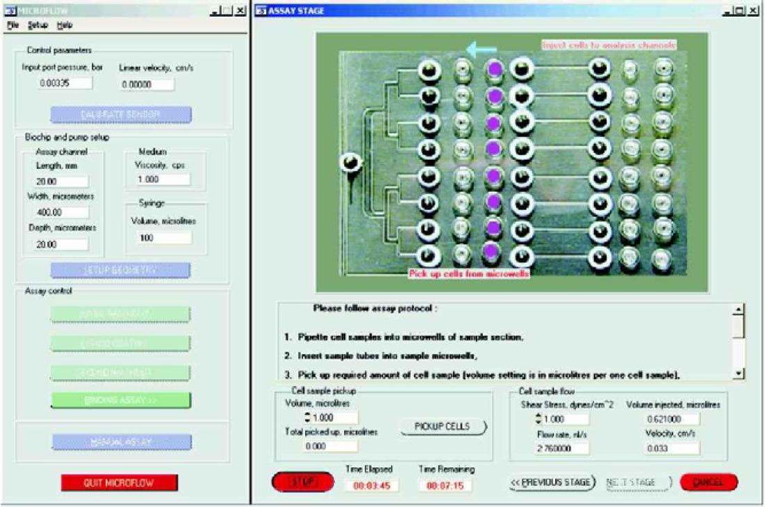
Biochip control software illustrating protocol for 8-channel biochip.
There are four steps in order to carry out a cell-based assay using this system:
The entire system should first be washed out or primed using a system liquid, PBS or culture medium, depending on the assay to be executed. This involves connecting the splitter-section to the analysis-section via disposable tubing and following the protocol in the text-box.
The analysis section is coated with the ligand/substrate chosen by the user and left for a specified time (usually at 4°C, overnight) to enable adherence to the channel walls.
The system is again completely washed out prior to the assay, thereby removing excess ligand/substrate present in the microchannel.
The cells are injected into the analysis section. This involves first placing the cells in the microwells and aspirating the required volume with the syringe pump. The tubing is then connected to the analysis section and the cells are dispensed into the microchannels. Here, the user may set several parameters prior to dispensing the cell suspension or simply do it manually as mentioned. Shear stress may be predetermined and the computer will automatically indicate to the user how much volume is required based on the geometry of the channel of that particular biochip. Additionally, flow rate and linear velocity are automatically calculated and monitored throughout the assay.
Such a system was also used to characterise reactions of PBLs to specific ligands, namely VCAM-1 and ICAM-1, at varying concentrations and in combination with each other. VCAM and ICAM are ligands which are highly expressed on the surface of endothelial cells in inflamed capillaries. They elicit specific responses from cells which flow through the inflamed capillary, such as adhesion and active locomotion. Preliminary results from our continuous flow assays to date appear to corroborate this scenario, see Fig. 5.
In each of the assays, the microchannels were initially coated with VCAM-1, ICAM-1 and a combination of the two at varying concentrations; so for example, one chip might contain the following coatings:
Channel 1: VCAM-1 at 20μg/mL; channel 2: VCAM-1 at 10μg/mL; channel 3: VCAM-1 at 1μg/mL; channel 4: ICAM-1 at 20μg/mL; channel 5: ICAM-1 at 10μg/mL; channel 6: ICAM-1 at 1μg/mL; channel 7: VCAM-1 and ICAM-1 at 20μg/mL; channel 8: control. Pre-activated PBLs were then injected into the channels of the microfluidic biochip. The response of the cell was then recorded according to the percentage adhering and also polarization of these cells. In each of these assays, the shear stress was set at 1 dyne/cm 2 , where the cell concentration was constant at 2 × 10 6 cells/mL. A cell sample volume of 1μL was used in each assay; therefore only 2000 cells were used in each assay.
Conclusions
In summary, the microfluidic enabling platform comprises two parts, namely, the microfluidic syringe pump with accompanying software and the microfluidic biochips, which together provide an experimental set-up which models the in vivo situation resulting in more informative cell-based assays.
Microfluidics is currently creating a huge impact as a new screening tool in drug discovery. Augmenting sample handling in laboratories has been one of the key contributors to improving productivity, especially in clinical laboratories and in the pharmaceutical industry for high throughput screening of drug candidates. However, apart from drug screening, there are a number of other applications to which a microfluidic enabling platform for cell-based assays may be used: binding studies/interaction studies, key experiments in immunology, physiological studies and gene expression experiments, with nucleic acids and proteins.
In addition, it may be possible to adapt this platform technology to work in combination with other methods such as: video microscopy software, fluorescence detection (demonstrated), proteomics/protein arrays, DNA micro arrays, single cell PCR, and transfection in situ.
Acknowledgements
The microfluidic syringe pump and microfluidic chips were jointly developed by Dmitriy Kashanin and Vivienne Williams at the Department of Physics, Trinity College Dublin. Testing of the chips was carried out at the tissue culture facility located at St. James's Hospital, Dublin by Siobhan Mitchell and Yuri Volkov.
Due to the recent success of this project, research groups involved were awarded an ATRP (Advanced Technology Research Programme) grant, which is currently being used to spin off a campus company through the commercialisation of this research. As such, the authors would like to thank Enterprise Ireland and Bioresearch Ireland for their support in helping to continue and develop this work