
Abstract
Seyonic is developing a family of high-speed micro flow sensors with full-scale sensitivities between 0.25 and 10 microliter per second. The flow rate is determined by the measurement of a pressure difference across a fluidic restriction, using two integrated piezo-resistive pressure sensors. Main applications are in sub-microliter dispensing systems, where both sensor accuracy and speed provide real-time validation of the requested liquid volumes. The very fast response of the sensor, less than 2 ms, allows for measurement of liquid volumes down to the nL range. The sensor is able to measure not only the flow, but also the instantaneous pressure in the systems under evaluation. It is therefore possible to obtain valuable information on the system's operation for the characterization of fluidic components such as micromachined pumps, solenoid valves and jet dispensers
INTRODUCTION
Applications requiring accurate measurement of sub-microliter to nanoliter quantities, for both research and industrial purposes have increased significantly over the last few years. Complex instrumentation is required for drug discovery and medical diagnostic, where increased throughput translates into steadily decreasing sample sizes and higher operating speeds. Reliable, accurate and fast liquid handling systems are of prime importance for these applications, and there is a growing need for active verification of the proper operation of these massively parallel instruments. Real-time measurement of liquid flow rates with nanoliter resolution using Seyonic's piezo-resistive flow sensor is a valuable tool for the development and operation of sub-microliter dispensing systems. The prime advantage of the applied differential pressure principle is the very rapid response of the sensor that allows dynamic measurement of flow with millisecond resolution. Furthermore, by using microfabrication technology, the sensor size is greatly reduced. Integrated with the use of well-developed microelectronic hybrid assembly techniques, this sensor is thus perfectly suited to the need for miniaturization of dosing functions in compact multi-channel instruments.
FLOW SENSOR
The flow sensor is based on a differential pressure measurement across a flow restriction. The pressure drop caused by viscous liquid flowing through the micromachined channel is, at low Reynolds numbers, directly related to volumetric flow rate as shown in Equation 1:
where Δp is the pressure drop [Pa] and Qv is the volumetric flow rate [m3/s]. C is a dimensionless friction factor and m is the (temperature dependent) fluid dynamic viscosity [Pa.s]. The full-scale flow sensitivity of the sensor can be adapted by choosing the appropriate values for the geometrical parameters A, L and DH. A is the channel cross-section [m2], L is the channel length [m] and DH is the equivalent hydraulic diameter [m], equal to 4A/wetted perimeter. The most used flow sensor device has a full-scale output of 10 μL/s, with water as a working fluid. Using different design parameters for the fluidic restrictor, full-scale flow ranges down to 25 nL/s can be achieved.
The flow sensor is based on a modified commercially available low-pressure sensor [1]. As a final step in the processing of the sensor wafers, a flow restrictor is etched between two adjacent pressure sensors on the backside. The silicon wafer is subsequently bonded onto a glass wafer with through holes for the fluidic connections. The size of the flow sensor chip is 4.5 × 9.0 × 0.9 mm3. The sensor is diced from the wafer and mounted stress-free onto a ceramic substrate, again with through holes for the fluidic interconnections, using silicone sealant joints. Electrical contacts are made to a metalization pattern that is screen-printed on the ceramic substrate. The sensor assembly is thus fully compatible with well-developed hybrid assembly techniques, ensuring high reliability and large volume capability. In addition, the liquid is completely isolated, by design, from the electrical side of the sensor, which is a key feature for micro-fluidic components.
The piezo-resistors of each pressure sensor are connected in a Wheatstone bridge configuration. Both the inlet and outlet pressure signals are measured. The flow rate output is extracted by subtracting the two pressures. The inlet and outlet pressure sensors have a 200 mbar full-scale output. The flow sensor chip is assembled in the form of a hybrid module with electronics integrated onto the ceramic substrate, providing amplified 0–5V pressure signals. Temperature compensation schemes are applied for both the pressure sensor parameters and the liquid viscosity and accuracy better than 2% of the full-scale flow is achieved for temperatures from 20 to 50°C.
The module dimensions are 8 × 30 × 2 mm3. Figure 1 shows a photograph of a packaged flow sensor module. The size of the ceramic substrate permits the integration of the sensor in a manifold of 9 × 9 mm2 footprint, that can be assembled into linear or rectangular arrays that fit the micro titer plate format. Figure 2 shows an assembly of three dispenser heads, each consisting of a flow sensor module, a solenoid valve, and a dispenser tip.
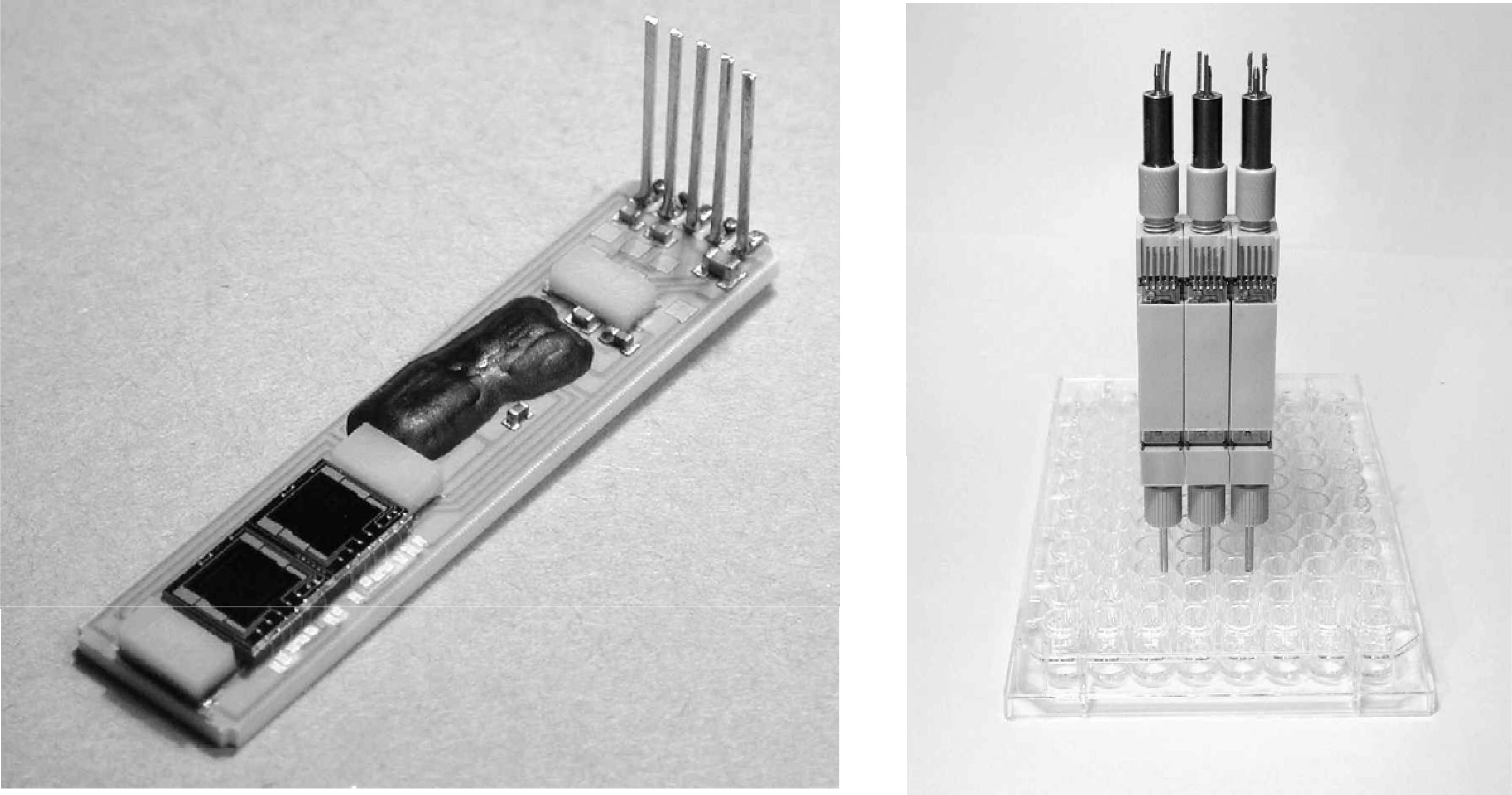
Assembled flow sensor module with integrated electronics, suited for multi-channel applications with 9 mm spacing.
PRESSURE-DRIVEN DOSING SYSTEMS
A typical application for the flow sensor is measurement of dispensed liquid volumes in a pressure-driven dosing system. The sensor is coupled to a solenoid valve, and integration of flow over time gives the dispensed volume. Because of their compactness, the sensor and valve can be placed directly on the dispenser tips while providing individual control for each channel. Therefore, the pressure driven system has a distinct advantage over systems that work with parallel moving plungers in the dispensing head. Compared to systems with individual syringe pumps per channel, the pressure-driven system is also more precise as it controls the flow of liquid at the point of dispensing and avoids long lengths of flexible tubing that may influence accuracy. The fact that the dispensed volumes are measured in real-time provides an important asset for quality control purposes.
Figure 3 shows a recording of a contact-less dispensing of approximately 100 nanoliters for a valve opening time of 10 milliseconds.
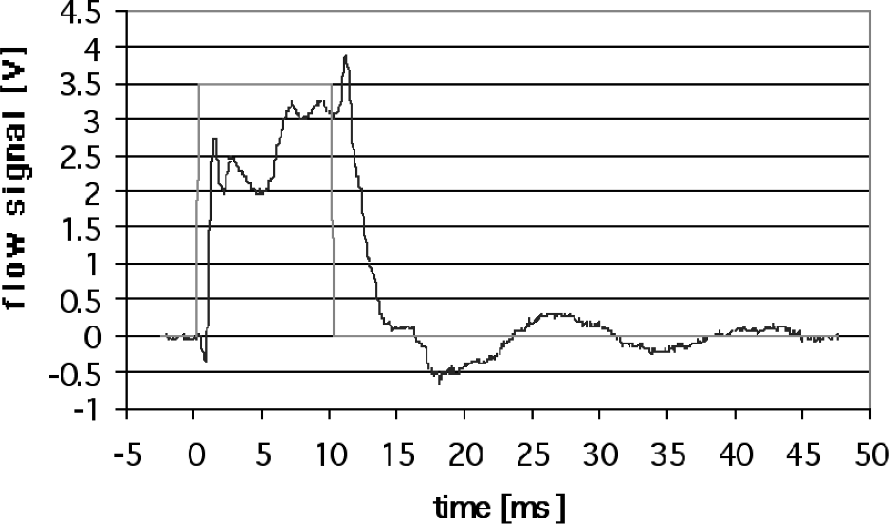
The flow sensor is placed between the pressurized reservoir and the solenoid valve. After the valve, the liquid is ejected into air from a nozzle. The flow profile reveals a number of important points. First of all, the dynamic characteristics of the valve can be observed. Opening takes place in less than 2 milliseconds while closing the valve lasts about 5 milliseconds. Furthermore, the flow is not constant, showing different types of fluctuations. A rapid oscillation of about 1.2 kHz can be traced to the actuation of the valve, whereas a lower frequency of about 65 Hz is due to the mechanical properties of the flow manifold and the connected tubing. For calibration purposes, the integrated flow signals are compared to gravimetric measurements of the dispensed volumes and show a perfect correspondence. The exact operation of the dispenser can thus be verified and controlled instantaneously.
CONCLUSION
The measurements show that the flow sensor reveals important real-time information about the operation of the fluidic system. It is thus a very useful tool in the development of micro liquid handling systems. However, application is not limited to development. Due to its very small dimensions, the flow sensor modules can be integrated into each individual channel of a parallel dispensing system. This implies that the operation of each channel can be independently verified and controlled with nanoliter resolution. The spacing between the channels is 9 mm in both X and Y directions. Because of the modular approach, systems based on this flow sensor can be easily adapted to different applications.