
Abstract
This research investigates the technique of image subtraction to find the discrepancy between healthy and illness MRI images. The technique developed in this research moves the healthy MRI image to overlap with the illness MRI image. Then, the two MRI images are aligned to the same orientation. After the healthy MRI image is overlapped with the illness MRI image, the illness MRI image is subtracted from the healthy MRI image. If there is discrepancy in the illness MRI image after the image subtraction, the discrepancy will remain in the subtracted result. The machine does the entire inspection automatically. There is no further human effort involved. The technique developed in this research can accurately find the discrepancy between healthy and illness images. This paper explains the method using the second moment to find the orientations of the MRI images. Using the orientations of the MRI images, the healthy MRI image and the illness MRI image can be aligned to the same orientation. The detailed process of image rotation is addressed in this paper.
INTRODUCTION
Currently, the only efficient way to locate MRI image discrepancy is using human brains. Now, researchers are trying to develop new technology to detect the discrepancy by machine. Past work in this area has used several different kinds of strategies to detect the discrepancy of the MRI image. They are — neural network [4][15], elastic frame matching [11][15], isodensity line [12], template matching [3][9][15], geometric and feature-based matching [3][10][12], profile description [1], volumetric frequency representation [2], biometrics [6], optimal separating hyperplace [13], Gabor wavelets [14], coding representation [11], and optical network. However, some of them need a lot of computation time [9][12]; some are very sensitive to noise [9]; some have very complicated mathematical models [12][15] and some have very complicated neural training algorithms [4][12][15]. Here we propose a different approach, which combines several techniques, to cope with the MRI image shifting and rotating problems. Thus, after the pictures of the MRI images are taken, the algorithms developed here can automatically locate the discrepancy of the MRI images without involving further human effort.
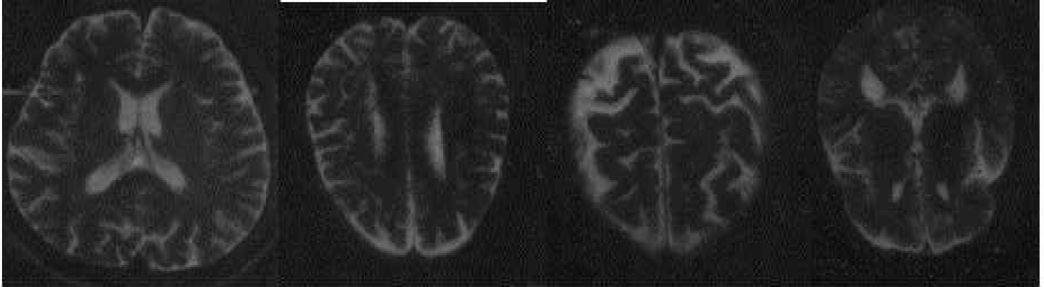
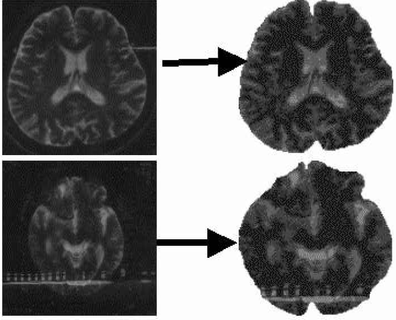
In this research, there are two kinds of MRI images. The first kind of image is called the healthy MRI image. The second kind of image is called the illness MRI image. The healthy and illness images are shown in figure 6. The discrepancy of these two kinds of images can be detected by the technique developed in this research. Since the backgrounds are irrelevant to find the orientation and the center point of the image, the backgrounds are removed from the MRI images. The result is shown in figure 2. Major axis and centroid algorithms are used to find the orientations and the center points of these two images. Both algorithms can very precisely locate the centroids and orientations of these MRI images. This research only processes the two-dimensional images. The three dimensional images are not investigated in this research. First the healthy MRI image is shifted to make the centroid of the healthy MRI image overlap with the centroid of the illness MRI image. Then, the healthy MRI image is rotated. Thus, the healthy MRI image can be aligned to the same orientation as the illness MRI image and image subtraction can be applied to the two images. The subtracted result precisely shows the discrepancy of these two MRI images. Under normal circumstances, when the MRI images are taken, even though they are slightly shifted or rotated, the algorithms developed in this research will still correctly find the discrepancy of the healthy and illness MRI images.
MRI IMAGE EXTRACTION
In order to find the locations and orientations of the MRI images, the important features of them must be extracted. Previous research has developed information about object enhancement and object extraction. In many cases, the image extracting technique works well to extract the feature of the object. In this research, we do not examine the object extraction process. Instead, the technique provided by other researchers, is used to extract the object. The extracted images are shown in the following figure.
FINDING THE CENTROID AND ORIENTATION OF AN EXTRACTED MRI OBJECT
The size of the image used in this research is a 128*128 image array. The centroid (xc,yc ) of an image can be found by the following equations:
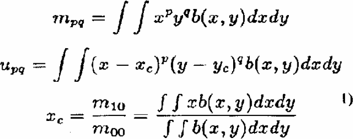
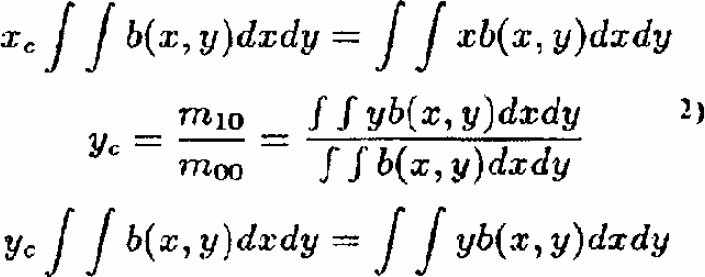
In the above equations, b(x, y) represents the gray level on location (x, y); (xc, yc ) represents the centroid of the MRI image.
USING THE SECOND MOMENT TO FIND THE ORIENTATION OF THE MRI IMAGE
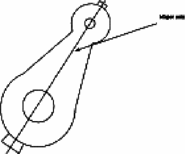
The major axis is the axis around which the object will have the minimum moment of inertia (Figure 3). This is useful in determining the object's orientation.
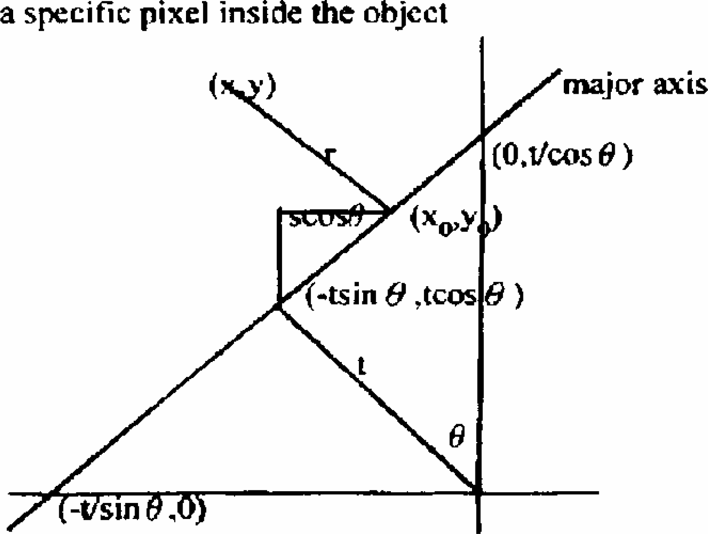
Figure 4 shows the relative position of the major axis. The major axis and X-axis generate an angle 0. The shortest distance from the origin to the major axis is t. The major axis and X-axis intersect at the point (-t/sinθ, 0). The major axis and Y axis intersect at the point (0, t/cosθ). The point inside the major axis with the minimum distance to the origin is (-t*sinθ, t*cosθ).
The relative position of the major axis
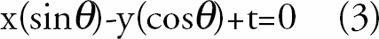
By analyzing figure 4, the equation for the major axis can be expressed as:
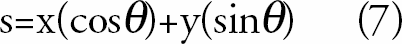
In figure 4, suppose one specific point (x0, y0) is located inside the major axis. From point (x0,y0) to point (-t*sin£c, t*cos£c), the distance is s. From figure 4, one can find:
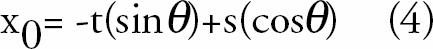
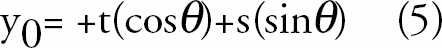
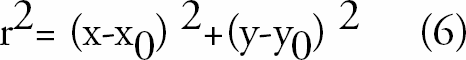
Given a point (x,y) on the object, r is the shortest distance between (x,y) and (x0,y0). Clearly,
Equations (4) and (5) are substituted into equation (6). The obtained result is differentiated with respect to s. Setting the result equal to zero, the following equation can be obtained.

The second moment, which describes the object, is:
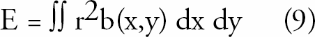
Where r is the minimum distance of one specific pixel inside the object to the major axis and b(x,y) is the gray level of pixel at location (x,y).
By analyzing equations (1), (2), and (9), the following equation can be derived:


The second moment, which describes the object, is:
Where r is the minimum distance of one specific pixel inside the object to the major axis and b(x,y) is the gray level of pixel at location (x,y).
By analyzing equations (1), (2), and (9), the following equation can be derived:

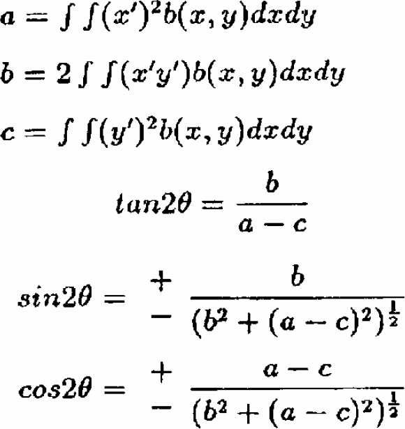
Differentiating with respect to 0 and setting the result to 0, the following equation can be obtained:
The values of a, b, c, and θ can be found for any images. The θ will represent the angle of the major axis with respect to the x axis. Based on θ, the algorithm can find the orientation of the object. The above second moment equation to find the object orientation can be summarized by the following equations:
GEOMETRIC COMPARISON OF THE MRI IMAGE
MRI IMAGE SHIFTING AND ROTATING
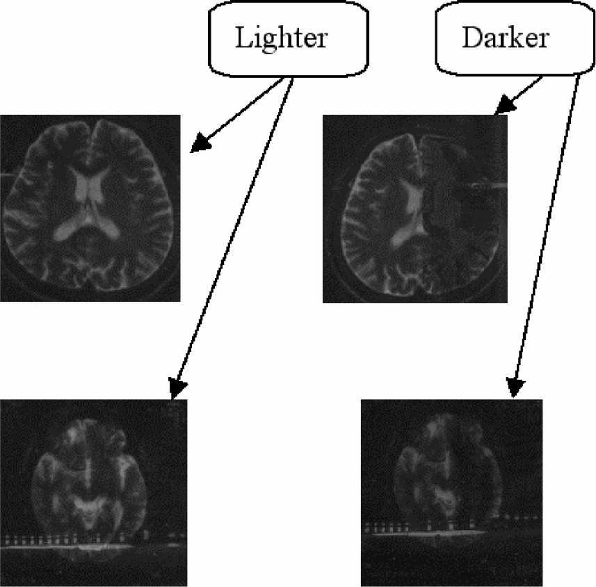
Using the method described in the previous section, the orientation of each extracted MRI image can be found. In this research, there are two kinds of images: the perfect (healthy) image and the flawed (illness) image. The healthy and illness images are shown in the following figures:
The MRI images in (b) and (d) display darker areas on the right than those in (a) and (c).
As mentioned before, in order to overlap the healthy image with the illness image, the healthy image needs to be shifted and rotated. In this section, the image shifting and rotation is addressed.
Figure 5 shows the corresponding position after the healthy image is rotated θ degrees toward the illness image. (i, j) is the location of one specific pixel inside the healthy image. The point (i, j), after being rotated θ degrees, will move to position (i', j'). Clearly, from figure 5, one can find i=rsinω, j=rcosω, i'=rsin(θ +ω), and j' = rcos(θ+ω). Since sin(θ+ω)= sinθcosω+cosθsinω, and cos(θ+ω)=cosθcosω-sinθsinω, the equations i' =jsinθ+icosθ, and j' = jcosθ-isinθ can be obtained. If the rotated direction is clockwise, then θ is positive; otherwise, θ is negative.
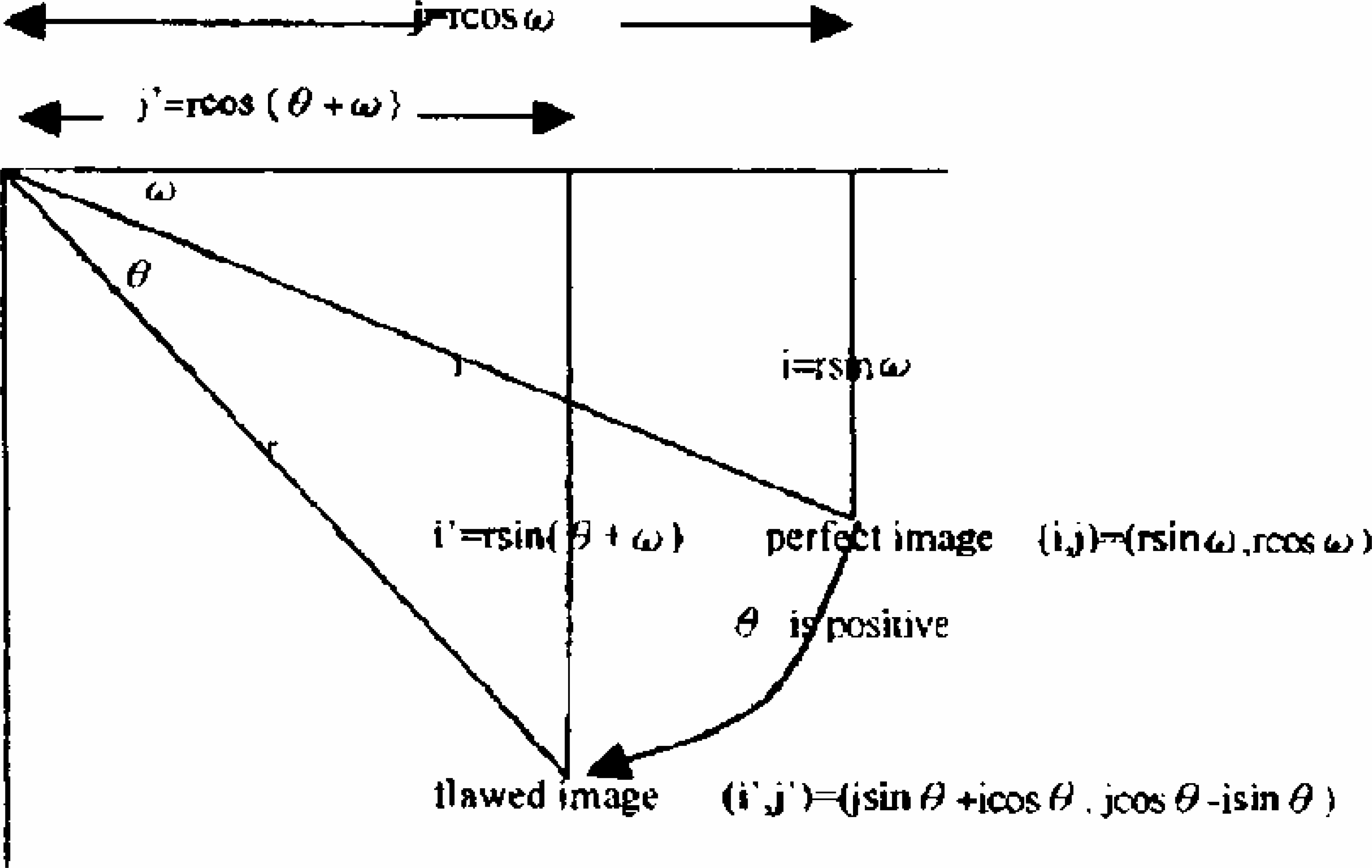
The corresponding position after the perfect healthy image is rotated 0 degrees toward the flawed (illness) image
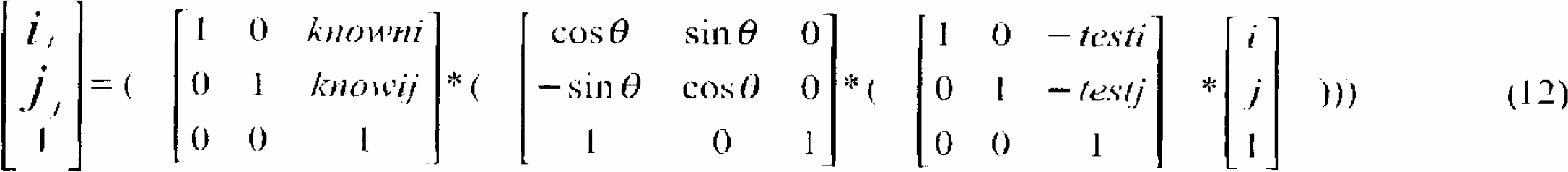
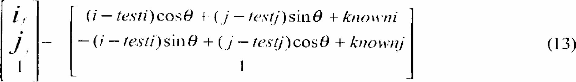
By analyzing figure 5, equation (12) can be obtained. This means that the healthy image is translated such that the centroid is moved to the origin of the coordinate. Next the picture is rotated such that the healthy image is at the same orientation as the illness image. Finally the picture is translated so that the healthy image centroid and illness image centroid are overlapping. Equation (13) carries out these operations by combining both the image rotation and image translation in one step. By using equation (13), the algorithm can rotate and transfer the healthy image point (i,j) to its proper position (i f,j f). (i f,j f) represents the position in the illness image which corresponds to the position (i,j) in the healthy image.
INTERPOLATING THE NON-INTEGER POINT
In this research, there are two kinds of image movement: image translation and image rotation. Simply shifting the pixels inside the healthy image so that the centroid of the healthy image is overlapping the origin of the coordinate completes image translation. After performing image translation, the location of pixels in the healthy image may have non-integer values.
After performing image rotation, the new position of a pixel might not be represented by integers either. The relative position of the sub-pixel (i,j) is shown in figure 7.
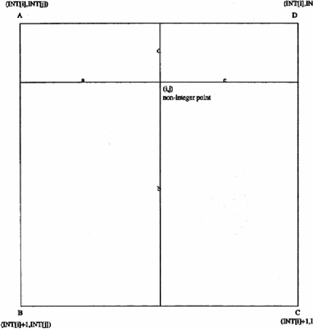
Show the relative position of the sub-pixel(ij)
To directly compare pixels from the healthy image to pixels from the illness image, it is necessary to find values for pixels in the healthy image at the same points (integer values) as those in the illness image. The non-integer coordinate positions, which are obtained from the calculation of equation (13), have different distances to their four neighboring integer pixels. The gray level of these non-integer points needs to be interpolated from their four neighboring integer pixels in order to obtain their proper gray level values.
GEOMETRY COMPARISON
After the image interpolation, the illness and healthy images lie in the integer points. Both images have the same orientation. The centroids of both images are overlapped. Image subtraction can now be applied to both images.
RESULTS AND CONCLUSIONS
Since one can find the centroid and orientation of the MRI image by using the previous mentioned rotating, transferring, and interpolating technique, the illness MRI image can be aligned to the same orientation as the healthy image. The rotated and shifted images are shown in figure 8.
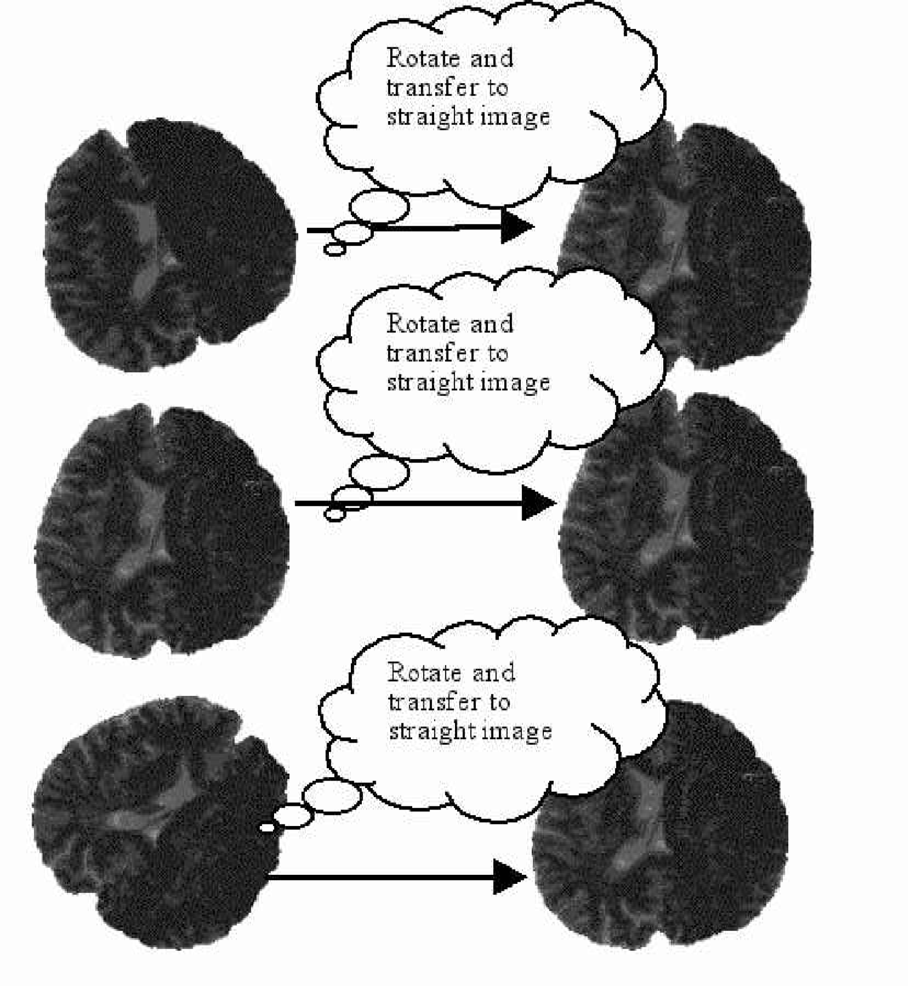
The illness MRI images are rotated and transferred. The illness MRI image is moved to the same orientation and centroid, which the healthy MRI image has.
After the transferring, the image subtraction is performed on both images. The subtracted image is show in figure 9. In this case, since the illness image in the right-hand side is darker than the corresponding right-hand side portion of the healthy MRI image, the subtracted result is not totally black. As shown in the final result of figure 9, the right-hand side of this subtracted image has light spots. These light spots show the discrepancy of the healthy and illness MRI images.
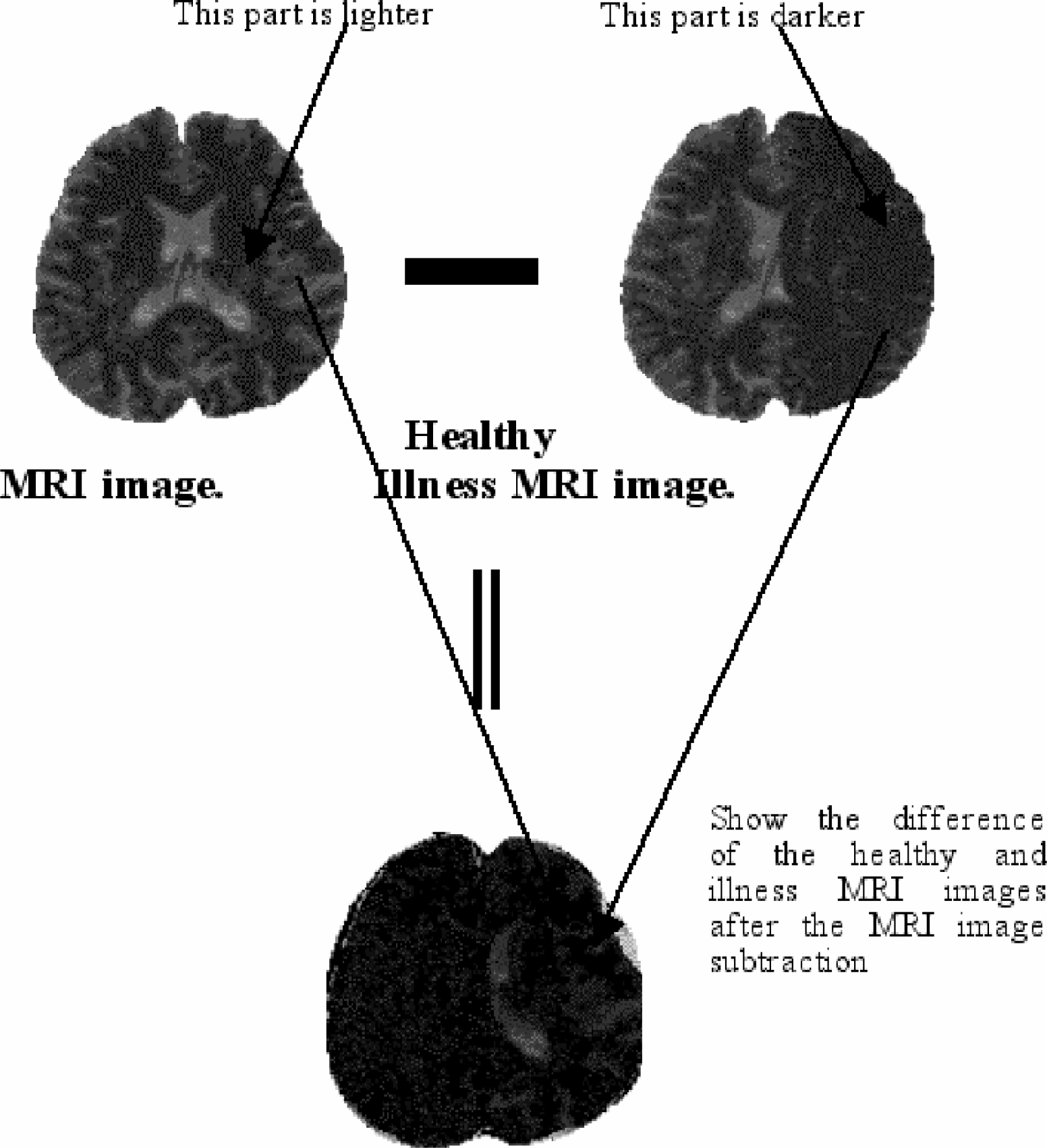
The healthy and illness images are overlapped and subtracted.
Therefore, one can use the technique developed in this research to find the discrepancy between healthy and illness MRI images.