
Abstract
The motion of a stick-slip microrobot propelled by its piezoelectric unimorph legs is mathematically modeled. Using a continuously distributed mass model for the robot's body, the working equation of the mechanism is derived based on the assumption of linear Euler-Bernoulli beam theory and linear piezoelectric behavior. Moreover, the required condition for generating net motion is calculated in terms of physical characteristics of the microrobot. It is demonstrated that the higher the friction constant, then a lower average speed is obtained. Also, it is shown that a microrobot with heavier legs can move in a rougher environment. Regardless of the mass proportion between robot's main body and its legs, a certain level of speed can, always, be achieved. The proposed results will be well suited to design, construct, and control the microrobots moving with piezoelectric benders, as their feet.
Introduction
Recently, the growing interest in microrobotics leads to emersion of numerous possible applications of miniaturized robots in fields such as medicine, observation and inspection, micro manipulation, defense, micro-biology, and search and rescue (Driesen, W. et al., 2007; Ebefors, T. et al., 1999; Breguet, J.-M. et al., 2007). This calls for developing different locomotion concepts and actuation mechanisms which can provide fast motion as well as highly precise resolutions. Stick-slip motion, impact drive principle, inchworm type, walking locomotion, etc are some of typical locomotion concepts which are employed in various designs presented by researchers (Ebefors, T. et al., 1999; Driesen, W. 2008; Dario, P. et al., 1992).
Stick-slip concept, as an inertial drive locomotion principle, has been introduced for the first time by Besocke (Besocke, K., 1987) in a Scanning Tunneling Microscope (STM). Afterwards, this principle and other corresponding variants are employed in many designs such as SPIDER-I (Rembold, U., 1997), MINIMAN project (Fatikow, S. et al., 2000; Eisinberg, A. et al., 2007; Wörn, H. et al., 2000), NanoWalker and NanoRunner (Martel, S. et al., 1999; Martel, S. et al., 2000), etc. Piezoelectric actuators, due to their high bandwidth, are frequently employed to actuate most of these high precision positioners (Driesen, W., 2008). A sawtooth voltage function with a linear ramp is often applied for the stick-slip actuators.
Here in this research, we propose a mathematical model to investigate the motion of a legged, piezoelectric driven microrobot working with stick-slip principle. In a similar article, Felso has presented a theoretical analysis of a one leg microrobot in which the mass of its leg is assumed to be negligibly smaller than that of the robot's main body (Felso, G., 2000). In reality, disregarding feet's mass would not be a correct and applied assumption and may result in considerable errors in design, construction, and control of a legged microrobot. Hence, in the present work, we consider a microrobot whose legs are of continuously distributed mass and elasticity. Hamilton's principle is employed to formulate the equation of motion. It is assumed that only the fundamental mode is excited during each step. Then, the response of the forced vibration of the system under effect of driving voltage is determined based on the assumed-mode method. Thereafter, the required condition for generating the net forward motion in terms of the physical characteristics of the mechanism and the involving frictional force is calculated. Finally, the effect of the mass distribution between the robot's main body and its legs on the average velocity is examined and some predictions for appropriate operating conditions of the microrobot are provided.
The moving principle of the microrobot
Generally, the complex motion process of microrobots in various locomotion concepts is inspired from that of vertebrates in nature. Therefore, it is necessary to simplify the motion process to be studied. Here, we consider a legged microrobot operating based on stick-slip principle to achieve a stable motion. Typical number of legs for may be two, three, or four legs. With all legs assumed to move simultaneously in the same phase with each other, we can simplify our microrobot's model to that shown in Fig. 1a. In this model, the robot's platform, standing on a piezoceramic leg, moves in a horizontal path without any angular distortion. Also, the vertical movements of all points of the system are presumed to be so small that can be neglected. Maintaining these conditions, the validity of the proposed model would be acceptable.
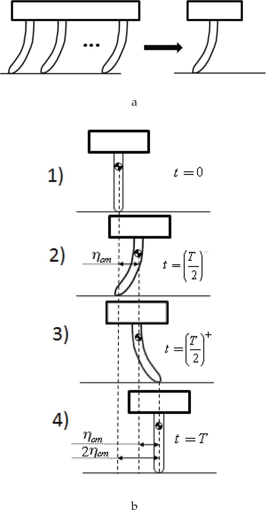
Schematic diagram of microrobot model: a) Simplified one-leg robot, and b) Stick-slip sequences.
The stick-slip sequences of the microrobot are illustrated in Fig. 1b. To actuate the piezoceramic leg, a sawtooth signal function with a linear ramp is applied, as follows

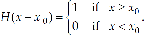
where H(x) is the Heaviside step function, and
During the ramp phase, the main body of the robot moves forward with an average velocity depending on physical characteristics of the system, while the robot's leg sticks to the substrate at the tip. As the tangential contact force at the tip exceeds a predefined threshold and at the input voltage switch (at t=T/2), the leg slips on the substrate and the robot returns to its initial configuration. During this last phase the leg follows a forward whipping motion while the body moves backward. The amount of backward motion of the body is a function of the mass proportion between robot's platform and its leg. Following this phase one step is complete.
As shown in Fig. 2a, the unimorph piezoceramic leg of the robot is composed of a piezoelectric material and a metal layer. Hence, to analyze the dynamic behavior of such a continuous system, the vibration analysis is essential. In what follows, we intend to derive the equation of motion of the microrobot.
To specify the position of every point in the system we make use of generalized coordinates such as shown in Fig. 2b. Thus, for an element within the leg of the robot

where Ƞ(x,t) indicates the horizontal movement of any point on the leg, p(t) denotes the position of the leg's tip, and w(x,t) is the deflection of the leg with respect to the leg's axis, which goes through the mass center of the robot's main body.
Using Hamilton's principle yields

where δL and δW
V
are the variation of the Lagrangian and the virtual work done by the applied voltage V
p
(t), respectively. The variation of w(x,t) vanishes for all known instants, i.e.,

Wang et al. demonstrate that, for cantilever unimorph piezo-actuators, maximum tip deflection and, consequently, energy transduction from electrical energy to mechanical energy (i.e., electromechanical coupling factor) is obtained when the following relation holds (Wang, Q. et al., 1999)

where E and h are the Young's modulus and the thickness of the composite layers, respectively. Also, subscripts p and m indicates piezo-layer and metal base, respectively. Furthermore, two non-dimensional parameters in (6) are defined as

Assuming the condition in (6) holds, the location of the neutral axis of the composite

By considering the walking sequences of the robot and the associated boundary conditions, it is evident that the mode shapes of leg's vibration would be similar to those of a cantilever beam with a moving base. Thus, we maximize the electromechanical coupling factor by choosing the thickness of each layer in accordance with (6).

a) schematic diagram of piezo-metal composite structure. b) generalized coordinates.
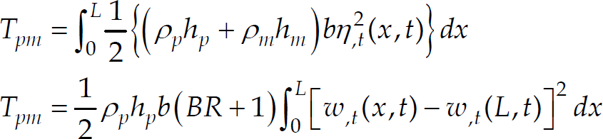
The total kinetic energy of the robot is obtained by adding the kinetic energy of the robot platform and that of the composite beam. The latter can computed as
where Ƞ,
t
and w,
t
represent the time derivatives of Ƞ and w and ρ
p
and ρ
m
are the densities of the PZT ceramic and the metal substrate, respectively, and R = ρ
p
/ ρ
m
. It should be noted that the time derivative of p(t) does not contribute in (9) since in each semi-period of motion (i.e., before and after t = T/2) this term is constant. On the other hand, the kinetic energy of the robot platform can be expressed as
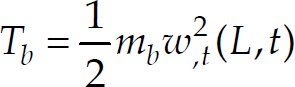
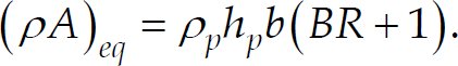
Thus,

where
Assuming the robot's leg to be homogenous and isotropic and obeying Hook's law within the elastic limit, we employ linear Euler-Bernoulli beam theory to extract the total strain energy of the leg. Hence, in the case that leg undergoes small vibration, we have

and from Hook's law we can write

Then, the total strain energy can be written in the following form,

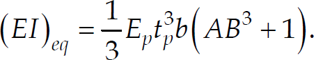
or equivalently

where
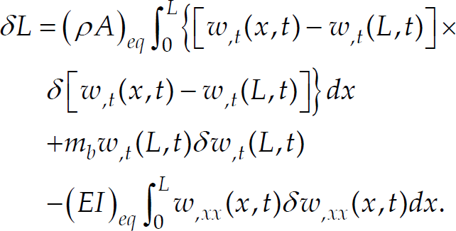
Now, we can construct the Lagrangian of the system as follows

Taking the variation of the Lagrangian yields
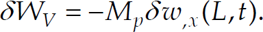
According to (Preumont, A., 2006), the effect of the piezoelectric layer on a substrate is equivalent to that of a bending moment proportional to the width of the electrode. Furthermore, when the width of the piezoelectric layer is varying, the effect of the piezoelectric layer is equivalent to that of a point force proportional to the first derivative of the electrode width. Also one should always keep in mind that piezoelectric loading leads to such a combination of internal forces which are in self-equilibrium (Preumont, A., 2006). Based on the foregoing discussion, applying voltage to the rectangular electrodes on the piezoelectric layer is equivalent to two bending moments M
p
at the ends, which are equal in magnitude and opposite in direction. Thus, the virtual work due to the applied voltage V
p
would be

where M
p
= (e31V
p
bh
p
) / 2 and e31 is the product of the piezoelectric constant d31 by its Young's modulus E
p
. Assuming stably horizontal motion of the robot's platform during each step, one can readily find that w,
x
(0,t) = 0 or δw,
x
(0,t) = 0. That is,
Substituting (19) and (21) back into (4), integrating twice by parts, and rewriting all the involving terms with respect to the variation of w(x,t) gives the equation of motion and the associated boundary conditions as


Noting the last boundary condition in (23) reveals that the term on the right side is an inertial force originated from the Newton's second law for the microrobot in horizontal direction, that is,

Finally, note that the only external force which is able to accelerate the microrobot in horizontal direction is the friction force F. We know that we must have
in which g is the gravitational acceleration, μ indicates the friction coefficient, and m represents the total mass of the robot. Hence, it is convenient to have the maximum of F when the leg has undergone the maximum deflection, implying F(T / 2) = μmg.
To solve the equation of motion, we make use of the assumed-mode method for the discretization of the distributed-parameter systems modified by addition of a mass, spring, or inertial force in the boundaries (Thomson, W. T. et al., 1998; Meirovitch, L., 2001). By first discretizing the kinetic energy, potential energy, and virtual work, this procedure resolves the problem of inhomogeneous boundary condition in the problem.
To this end, the stationary response of the system under action of the voltage V
p
(t) can be represented in terms of the generalized coordinates ψ
n
(t) and the normal modes φ
n
(x) as

Here, it is assumed that only the fundamental mode is excited. Therefore, using w(x,t) = φ(x)ψ(t) results in
where φ(x) is the first eigenmode of the cantilever beam (Tse, F.S. et al., 1978), prime denotes differentiation with respect to spatial variable x, and


The fundamental frequency of the microrobot can be easily obtained from (27) that is
For a sawtooth voltage function such as shown in (2), the solution of (27) can be divided into three different parts:
a) The first semi-period in the range of [0,T / 2) wherein the leg of the microrobot does not slide on the substrate and as a result p(t) = 0. As the voltage decrease from zero to -V0, the composite foot deflects to its maximum limit at which the sliding force F takes its maximum value μmg. b) t = T/2 at which the voltage jumps with a steep rise to V0. Indeed, this stage is very short with respect to T. Since the accelerating force −μmg, is also finite then, the speed change in this stage is negligible within this interval. Therefore, it is realistic to assume that the position of the mass center of the robot would not change during this stage. c) The second semi-period (T/2,T] wherein the voltage function decreases from V0 to zero. During this stage the microrobot, returns to its initial configuration, completing a full step. At the end of this stage the leg's tip adheres to the base again and the friction force comes down to the zero from the initial value of −μmg.
For the first semi-period, without loss of generality, we assume that the robot starts its motion from the origin, or ψ (0) = 0. Thus from (27), we have

for 0 ⩽ t < T / 2, and
for 0 ⩽ t< T/2.
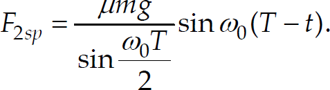
As discussed earlier, to determine the constant coefficient S, we use the fact that the sliding force F reaches to its maximum value μmg at the end of this interval, hence from (24),

Next, the sliding force through the first semi-period of motion can be found as

From the symmetry of motion at t = T/2, for the second semi-period one can write

for T/2 < t ⩽ T, which with some simplification takes the following form

for T/2t ⩽ T, where

Then, the sliding force during this period can be expressed as
This completes the solution of the problem in each of the three different stages of a step.
To characterize the complex motion of the microrobot, we define two average values: the step length (d) and the average speed (v
ave
), both of which are calculated within one period. The step length is the distance traveled within one period (see (35)):

The average speed is then:
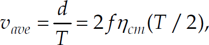
where f represents the frequency of the periodic excitation voltage.
The net forward motion is achieved if the average speed is nonzero, i.e.,

Substituting from (37) and (40) into (41) and simplifying yields

where the term on the left hand side of (42) is a positive dimensionless parameter and

which are all positive constants. From above definition, ζ denotes the mass contribution of the leg with respect to mass of the microrobot. As ζ varies from zero to one, the robot's mass m is shifted from the main body to its leg. α F is the ratio of the robot's weight to the piezo-induced force at voltage V0. Also, a i 's with i = {1,…,4} are positive constants depending on the eigen-function φ(x).
For a given set of system parameters, one can get the following condition in terms of μ for (41) to hold

which means that the microrobot do not move unless the friction coefficient is less than μ max . In other words, when the adhesion coefficient exceeds μmax, the robot oscillates in place rather than moving forward. To investigate the effect of varying ζ on the upper bound of μ, α F μmax is plotted in Fig. 3. This Figure illustrates that as the mass contribution of the robot's leg increases, the upper bound of the friction coefficient also grows if α F is unchanged. The plot shows that when ζ = 1 this limit can be nearly 30% higher than the case where ζ = 0.
Moreover, Fig. 4 shows the influence of ζ on the variation of the average velocity. As shown in this figure, as the mass of the leg increases, i.e., ζ grows from 0 to 1, the maximum average velocity of the robot decreases. One should note, however, a microrobot with a higher portion of its mass in the leg has the ability to move over a substrate with higher roughness than does a robot with its mass concentrated at its main body.

Influence of mass distribution parameter on upper bound of adhesion coefficient

Influence of friction coefficient on average speed of microrobot
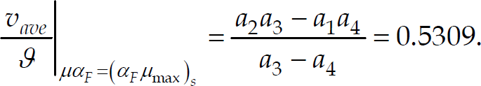
The above results might be utilized in the design of the microrobots moving with piezoelectric benders, as their feet. Besides, it is interesting to point out that, the average velocity for a special value of α
F
μmax is fixed and becomes independent of the mass distribution within the mechanism. This point can be found by setting the coefficient of ζ in (42) equal to zero,

which leads to
Finally, note from Eqs. (34) and (38) that in accordance with (Felso, G., 2000), the frequency of excitation must be always selected such that f > 2f0. In this way the calculated sliding force does not exceed the maximum value μmg. This condition restricts the lower limit of the driving frequency f, but the presented model, which ignores the vertical motion, is not able to pose an upper constraint on this frequency. On the other hand, Eq. (40) predicts that the higher the frequency of excitation, the higher average velocity can be attained. Indeed, ignoring the vertical motion of the microrobot leads to this unrealistic result. By considering the axial deformation of the leg and imposing a contact condition on the leg's tip, one can develop a more realistic model which resolves this problem.
This research proposed a mathematical model to express the stick-slip motion of a legged, piezoelectric driven microrobot. Each of robot's leg, which is a piezoelectric unimorph actuator, can be bent as a composite uniform beam by applying sawtooth voltage function. Hamilton's principle, linear piezoelectric relation and linear Euler-Bernoulli beam theory were utilized to derive the robot's equation of motion. A simple guideline was found for generating net motion in terms of robot's physical characteristics, friction coefficient, and applied electric voltage. It was demonstrated that the maximum allowable friction coefficient increases as the mass ratio of legs grows; that is, a microrobot with heavier legs can move in a rougher environment. However, a higher friction coefficient results in a lower corresponding average velocity. Furthermore, it is shown that the average velocity for a special value of system parameters is fixed and becomes independent of the mass distribution within the mechanism. The calculated expressions for the step length and the average velocity allows for dimensioning of the legs and might be effectively employed to meet the design objectives for a microrobot propelled by piezoelectric benders, as their feet. The presented model, besides its advantages, is not able to predict the maximum permissible excitation frequency, and further research is needed to better understand the effect of this parameter on the motion quality.