
Abstract
A piezo-driven linear actuator based on the improved stick–slip principle is developed in this article. With the help of two piezo-stacks and flexure hinges, the preload force can be changed, so the designed actuator can realize relatively large linear ranges and large output force. The designed actuator mainly consists of the mover, the stator, two piezo-stacks, an adjusting stage and the base. The working principle and theoretical analysis are described. A prototype actuator was fabricated and a series of experiments were carried out to investigate the work characteristics of it. Experimental results indicate that the maximum speed is about 3.086 mm/s and the maximum output force is 0.98 N. They are both improved compared with the traditional stick–slip motion. Experimental results confirm that the proposed actuator can realize large output force relatively and different motion speeds with high accuracy under different driving voltages and frequencies.
Introduction
Piezo-driven actuators are widely used in the precision positioning system due to their advantages that they can provide rapid response with high resolution in compact sizes. So far, many types of piezo-driven actuators have been developed in the field of precision positioning system. According to working principles, they can be mainly classified into direct driving actuators, ultrasonic actuators, impact driving actuators, inchworm actuators, stick–slip actuators and so on. All of these kinds of piezo-driven actuators have different advantages and disadvantages. Direct driving actuators can reach rapid response motions with high resolution easily, and the structures can be small and the output force can be large. But the motion range is limited, and the creep, hysteresis and nonlinearity cannot be ignored.1–3 Ultrasonic actuators are usually good at reaching high-speed motions and large ranges in small sizes, which are based on the elliptical motion of the contacting surface. However, the resolution and output capability are still the problems.3–6 Impact driving actuators usually have very simple structures, and they are easy to control, but the output force is also small.7–9 Inchworm actuators can achieve large motion ranges by stepping motions, and the output force is usually large. Nevertheless, the structures of them are usually complex, and they generally need at least three piezo-stacks; hence, the motion control is relatively complicated.10–12 Stick–slip actuators usually consist of only one active component, and they are easy to control and can provide unlimited motion ranges with high resolution at the same time. The very simple design of stick–slip actuators (consisting of only a few parts) allows for the miniaturization aspect with the potential applications for high-precision micro-systems. For example, SW Lee 13 proposed one piezoelectric multi-axis stage based on stick-and-clamping actuation technology, and the stick-and-clamping motion makes the backward motion reduced, so the stage can work more stably. JY Peng and XB Chen 14 proposed the dynamics model of a stick–slip actuator by taking into account the linear dynamics and hysteretic behavior of the piezoelectric actuator (PEA). H Huang and HW Zhao 15 designed one stick–slip actuator by the parasitic motion of a microgripper, and it could realize both forward and backward motion by only one piezoelectric stack. But most of the designed stick–slip actuators are working under constant preload force, so the output force of stick–slip actuators is limited.
This article uses another piezo-stack and one flexure hinge mechanism to change the normal force between the stator and the mover, so that to improve the maximum output force. Additionally, the flexure hinge mechanism will also produce the parasitic motion in the working direction which can enlarge the stepping displacement in one step. The experiments suggest that the proposed actuator can realize larger output force and moving speed relatively, and large motion ranges with high resolution as well. The designed actuator may have some significance for the application of stick–slip actuators.
Configuration and the working principle
Figure 1 shows the structure of the designed piezo-driven actuator, which mainly consists of one mover, one stator, two piezo-stacks, an adjusting stage and the base. Piezo-stacks A and B are installed in the stator to drive the mover. The mover is made up by one linear guide way and one block. The adjusting stage is used to adjust the preload force between the stator and the mover. All of them are assembled on the base carefully.
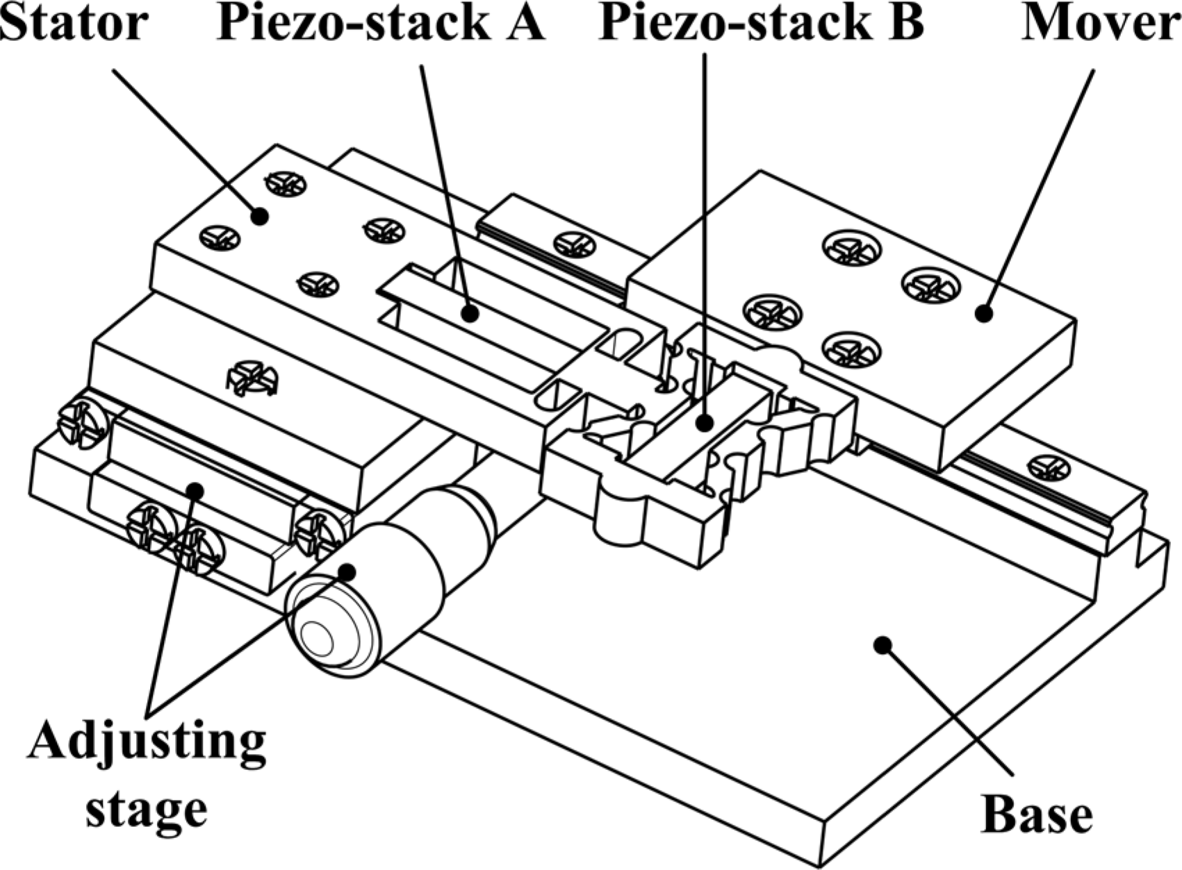
Structure of the designed nanopositioning actuator.
The input signals for the piezo-stacks A and B are shown in Figure 2. V 1 is the input voltage for piezo-stack A and V 2 is the input voltage for piezo-stack B. The sawtooth wave of voltages is used. According to Figures 2 and 3, the working process of one working circle can be divided into three steps.
Step 1. From time 0 to t 1, piezo-stacks A and B get charged at the same time, so piezo-stack B will hold the mover tightly. Under the action of flexure hinges, piezo-stack A will push piezo-stack B and the mover to move a small distance of ΔL, which is shown in Figure 3(a).
Step 2. At time t 1, the voltages of piezo-stacks A and B reach the largest value.
Step 3. During time t 1–t 2, both the voltages of piezo-stacks A and B become small and fast; due to the action of inertia, the mover will stay in the place of step 2, and the piezo-stack A will pull the piezo-stack B back to the initial position, as shown in Figure 3(c).

Input signals for piezo-stacks A and B.

Working process of one working circle: (a) stick motion, (b) largest position and (c) slip motion.
After the above three steps, one working circle is completed, and by repeating steps (1)–(3), the designed actuator can reach large-stroke linear motion, which is unlimited theoretically. Only when the piezoelectric stack A works, the actuator will move in the traditional stick–slip model. The output force can be enlarged using piezoelectric stacks A and B at the same time; this may bring more applications for the stick–slip actuators.
Design and analysis
Piezo-stacks A and B are assembled in the stator, so the structure of the stator will affect performances of the designed linear actuator. Flexure hinges are used into the design of the actuator due to advantages of simple and compact structure, no clearance and high positioning accuracy. The structure of the designed stator is shown in Figure 4(a). Right-angle flexure hinges are used for piezo-stack A to gather stable displacement in the working direction of x. Right-circular flexure hinges and the bridge-type amplification mechanism are used for piezo-stack B to gather the preload force and the parasitic displacement in the working direction, which can improve the output force and the motion speed than the ones of traditional stick–slip actuators. The linkage model of the designed stator can be seen in Figure 4(b).

Design of the designed stator: (a) structure and (b) linkage model.
The stepping displacement of contacting point C is made up of two parts: the moving distance
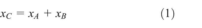
Since right-angle flexure hinges are used for piezo-stack A, the moving distance caused by piezo-stack A can be obtained as follows, where

According to the previous works,3,16 the stepping displacement can be obtained as equation (3), where

Here, the designed α is 30°, so equation (1) can be changed into the following

To verify the feasibility of equation (4), the finite element method (FEM) was used. Here, elongations of piezo-stacks A and B are both given as 10 µm, and the four holes are fixed. The analysis result is shown in Figure 5. The stepping distance of the contacting point C in the working direction x is 17.40 µm; it is less than the value obtained using equation (4), which is 18.66 µm. This may be caused by the calculation errors.

FEM analysis of the stator in the working direction.
Experiments
In order to obtain some preliminary knowledge of the feasibility and the behavior of the proposed linear actuator concept, a prototype was fabricated. A series of experiments were carried out to test the working performances of the designed piezo-driven linear actuator.
Experiment system
Figure 6 shows the experimental system for the designed linear actuator. The established system mainly consists of the personal computer, the signal controller, the signal amplifier, the laser sensor and the designed actuator. Two piezo-stacks AE0505D16 from Tokin Company are used in the designed actuator, and the size of them is about 5 × 5 × 18 mm3. When the system works, the signal controller from Delta Tau will generate the needed signals (sawtooth wave) which are shown in Figure 2, and then, the signal amplifier enlarges the signals to the appropriate value so as to drive the designed actuator. The motion displacement is measured by the laser displacement sensor LK-G10 from Keyence Company with a resolution of 10 nm and a reflector is placed on the designed actuator to reflect the laser. All the devices are put on one vibration-isolated optical table.

Experimental system of the designed linear actuator: (a) the established experiment system and (b) the local enlarging graph showing the prototype and testing in detail.
Performances
Figure 7 shows the comparison of the working performance under different working models: piezo-stacks A and B working together (red) and piezo-stack A working alone (black). The given frequency is 1 Hz and the input voltages for piezo-stacks A and B are the same. It can be seen that during one working cycle, the backward motion is observed, that is, when the mover reaches the maximum one-step-displacement L, it will move back for a displacement L 0. This may be caused by that during time t 1 to t 2 (see Figures 2 and 3), piezo-stacks A and B move back but the mover and the stator still contact; thus, under the action of the friction between them, the mover will move back for a distance as well. So, the real step displacement of the designed linear actuator is as follows

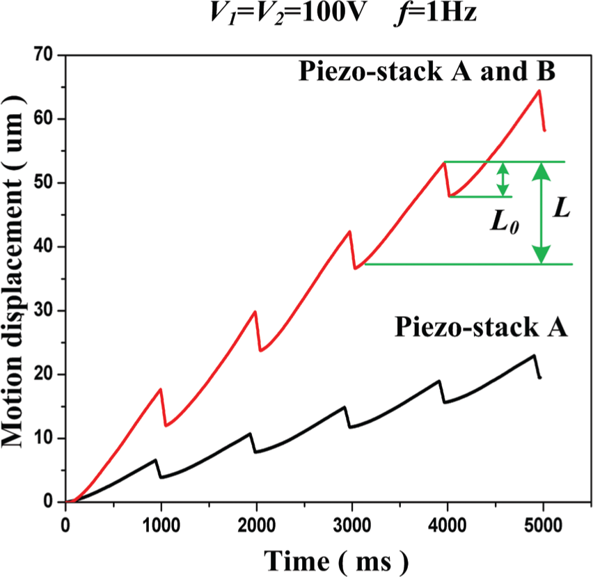
Working performance under two working conditions.
where
From Figure 7, we can also see that when piezo-stacks A and B work together (improved stick–slip motion), the stepping displacement is obviously larger than that when piezo-stack A works alone (traditional stick–slip motion). This result confirms that the designed linear actuator has relatively larger stepping displacement at the same condition, so does the motion speed of it, and the motion speed can be obtained as follows

where V is the motion speed of the designed actuator, f is the working frequency and
Figure 8 presents the working performances under different driving voltages; the given frequency is 1 Hz and the input voltages V 1 and V 2 are equal. When the driving frequency is low, the motion is relatively stable, here the given frequency is chosen as 1 Hz for it is easy to control and convenient to observe. As shown in Figure 8, the stepping displacement of the designed linear actuator increases along with the driving voltage. This is in agreement with the performance that the elongation of the piezo-stack will increase along with the driving voltage. When the driving voltage is below 20 V, the actuator cannot move forward stably, so the minimum stepping displacement (motion resolution) in one working circle is 0.41 µm. The maximum stepping displacement is 11.65 µm under 100 V, and it is much larger than that when piezo-stack A works alone, as is shown in Figure 9. This is mainly caused by the use of the bridge-type flexure hinge mechanism which has been introduced in Part III.

Working performances under different driving voltages.

Stepping displacement in one working circle under different driving voltages.
The motion characteristics of the designed linear actuator under different driving frequencies are provided in Figure 10, and the driving voltages for piezo-stacks A and B are both 100 V. Figure 10(a) is the result when the driving frequency is low: 1, 2, 3 and 5 Hz; Figure 10(b) is the result that the driving frequency is relatively high: 10–100 Hz. It can be seen that with the increase in the frequency, the backward motion is more and more difficult to observe, and this may be due to the very short interval of time for the flexure hinges to move back for a large displacement immediately before the next cycle comes.

Working characteristics of the linear actuator under different driving frequencies: (a) 1–5 Hz and (b) 10–100 Hz.
According to equation (6), motion speed is also one basic characteristic of actuators; the relationship between the motion speed and the driving frequency is illustrated in Figure 11, with a constant driving voltage of 100 V for both piezo-stacks A and B. When the driving frequency increases from 1 to 600 Hz, the motion speed of the designed linear actuator with piezo-stacks A and B will also increase. The maximum motion speed is 3.806 mm/s when the driving frequency and the driving voltage are 600 Hz and 100 V, respectively. After 600 Hz, the motion speed decreases quickly. When the driving frequency is higher than 700 Hz, the designed linear actuator cannot work stably, and this is may be caused by the use of the flexure hinges which bring a low stiffness.

Motion speed characteristics under various driving frequencies.
To test the output force of the designed linear actuator, a testing system was established, as is shown in Figure 12(a). A wire was used to hold the standard weight to produce the load. And the test results are presented in Figure 12(b). The preload force can affect the back-step displacement deeply, so we must adjust it properly (not to large, not to small) by the adjusting stage in Figure 1. When the designed stage can move stably, it will be adjusted. As we can see, in the case that piezo-stacks A and B work together, when driving frequency is below 200 Hz, the output force is around 0.9 N; after 200 Hz, the output force decreases quickly. But the influence of the driving frequency on the output force is small when piezo-stack A works alone. When piezo-stack A works alone, the maximum output force is only 0.696 N; when piezo-stacks A and B work together, the maximum output force of the designed linear actuator is 0.98 N. It can be seen that the output force of the designed stick–slip actuator is improved when the driving frequency is low. The stiffness of the used flexure hinges should be improved to increase the output force in the future.

Output force experimental results: (a) working schematic and (b) motion speed under different driving frequencies.
Conclusion
An improved stick–slip type piezo-driven linear actuator with the changeable preload force is introduced in this article. The designed actuator can realize relatively large linear range and large output force. The working principle and structure are expounded in detail. A prototype was manufactured and experiments were conducted to test the working performances of it. The maximum stepping displacement is obtained as 11.65 µm when the driving voltage and the frequency are 100 V and 1 Hz, respectively. The motion resolution is 0.41 µm with the minimum driving voltage of 20 V. And the motion speed and the output force were also given. The fastest motion speed is 3.086 mm/s with a constant driving frequency of 600 Hz and a constant driving voltage of 100 V. The maximum output force is 0.98 N when the driving voltage is 100 V.
In summary, the experiment data suggest that the designed linear actuator can realize good working performances on both the output force and motion speed. Future work will be conducted to improve the load capability under higher driving frequencies and analyze the influence factors such as roughness of the contacting surface and the stiffness of the flexure hinges. More researches about the working principle will also be done in the future.
Footnotes
Academic Editor: ZW Zhong
Declaration of conflicting interests
The author(s) declared no potential conflicts of interest with respect to the research, authorship, and/or publication of this article.
Funding
The author(s) disclosed receipt of the following financial support for the research, authorship, and/or publication of this article: This research is funded by the National Natural Science Foundation of China (Grant Nos 51275198 and 51105163), Special Projects for Development of National Major Scientific Instruments and Equipments (Grant No. 2012YQ030075), National Hi-tech Research and Development Program of China (863 Program) (Grant No. 2012AA041206), Program for New Century Excellent Talents in University of Ministry of Education of China (Grant No. NCET-12-0238), Specialized Research Fund for the Doctoral Program of Higher Education (Grant No. 20130061110026), Patent Demonstration Project for Research Team in Jilin Province (Grant No. 20130416015ZG), and Training project of the “Challenge Cup” by Jilin University (Grant No. 450060507040).