
Abstract
In this work the kinematics of the end of the spine is simulated by means of a five-degree-of-freedom decoupled parallel manipulator. The displacement analysis is presented in a semi-closed form solution, whereas the velocity, acceleration and jerk analyses are carried out by means of the theory of screws.
Introduction
The jerk, a research field of great interest in quite different academic communities, is the time rate of change acceleration and is related to the rate of change of force, namely an impulse which is considered as a hammer blow force. Particularly, it is known that there is a direct relationship between the jerk and the movements of the human body (Morasso, 1981; Flash and Hogan, 1985; Uno et al, 1989). Consider, for instance, that Crossman and Goodeve (1983) have shown that when high spatial precision is required, many movements related with the hands present irregularities and multiple velocity peaks. Gielen et al (1997) noted that the charactecteristic pattern of cerebellar ataxia, related with the jerk and submovements, is contained in the trajectory of the hand during repeated arm movements. Goldvasser et al (2001) investigated high curvature analysis and integrated absolute jerk for differentiating healthy and cerebellopathy patients performing pointing tasks. In order to understand how the central nervous system controls the kinematics of rapid finger and handmovement, Novak et al (2000) proposed an objective algorithm to identify overlapping submovements, detecting appreciable inflections in the acceleration traces which are related, evidently, with the jerk. Viviani and coworkers (Viviani and Schneider, 1991; Viviani and Flash, 1995) proved that there is a correlation between perception, motion planning, and jerk in human. The spinal column has been the motive of an exhaustive research field.
Basically, the motions of the spine can be classified in three types: a) sagittal plane movement, b) coronal plane movement c) transversal plane movement of axial rotation. Individual segmental range of motions was quantified for all spinal levels by Panjabi and White (1980). Dimnet et al (1982) reported a technique, based on lateral-view-X-ray, to determine parameters for describe the centers of rotation and curvature of the spine.
Gracovetsky and Farfan (1986) proposed a novel theory based on the mechanical behavior of intervertebral joints capable to compute both, spinal motions and muscular actions. By means of the technique of videofluoroscopy, Cholewicki and McGill (1992) studied the kinematics of the lumbar spine. Yoganandan (1993) determined the kinematic response of the lumbar spine using instrumented transpedicular screws and plates. It is well-known that a structure is any assemblage of materials that is intended to sustain loads, a strong argument to simulate the spine, in that way Levin (1995) identifies tensegrity structures whose elements always work in tension regardless of the direction of the applied force, an interesting option to simulate the kinematics of the spine. Willems et al (1996) provided preliminary information about the spatial kinematics of the thoracic spine in vivo. Faber et al (1999) proposed a method to compute Euler's angles of rotation of a body segment during locomotion and applied it to in vivo spinal kinematics. In order to demonstrate in vivo intervertebral coupled motions of the upper cervical spine, Yoshikawa et al (2004) studied the spatial kinematics of the upper cervical spine during head rotation using three-dimensional magnetic resonance imaging (MRI) in healthy volunteers. Ziddiqui et al (2006) investigated the sagittal kinematics in vivo of the lumbar spine at the instrumented level. Ishii et al (2006) studied the spatial kinematics of the cervical spine during lateral bending while Konz et al (2006) investigated the spatial kinematics of spinal during walking. Chanceya et al (2007) determined the center of rotation of the upper cervical considering pure bending. Gill et al (2007) examined the effect of changes in horizontal lift distance on the amount of flexion in different spine regions according to different lift styles. In order to approach the so-called shaken baby syndrome, recently Jones et al (2008) proposed a methodology for the kinematic analysis of infant spine.
It is straightforward to show that the movements of the spinal column can be simulated by assembling in series connection several parallel manipulators. In this way, in a recent contribution Zhu et al (2008) proposed some parallel manipulators to simulate the finite kinematics of the end of the spinal column. In this work not only the finite kinematics but also the velocity, acceleration and jerk analyses of the end of the spine are carried out by applying the theory of screws to a novel parallel manipulator.
Description of the parallel manipulator
The proposed parallel manipulator, see Fig. 1, consists of a moving platform and a fixed platform connected each other by means of three Universal + Prismatic + Spherical (U

The proposed base parallel manipulator
According to a revised version of the Kutzbach-Grübler formula, this parallel manipulator possesses five degrees of freedom, three rotations that are provided by the translational generalized coordinates {q3, q4, q5} and two translations that are provided by the rotational generalized coordinates {q1, q2}. The main merit of this topology, for brevity 3R2T, is that the position and orientation of the moving platform, with respect to the fixed platform, are controlled independently by means of the U
In this section, the displacement analysis of the mechanism under study is presented. The inverse position analysis (IPA) consists of finding the generalized coordinates of the parallel manipulator given the pose, position and orientation, of the moving platform with respect to the fixed platform; whereas the forward position analysis (FPA) consists of finding the pose of the moving platform given the generalized coordinates of the parallel manipulator.
Let XYZ be a global reference frame attached at the fixed platform and let xyz be a reference frame attached at the moving platform, see Fig. 1. Given the position, vector

On the other hand the lengths q3, q4 and q5 are obtained as follows

where the dot · denotes the usual dot product of the three dimensional vectorial algebra whereas S
i
and U
i
denote, respectively, the position vector of points S
i
and U
i
. Furthermore, any point P is computed upon point p, which is expressed in the frame xyz, as follows:

In order to compute the FPA, the point C is found rewritten Eqs. (1) as

that yields a closed-form solution Furthermore, with the purpose to compute the lengths q3, q4 and q5, consider the following closure equations
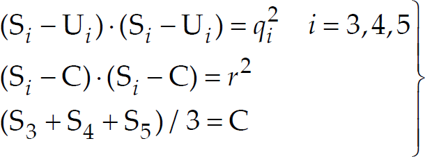
where r is the radius of the moving platform Expressions (5) are solved using recursively the Sylvester dialytic elimination method, for details the reader is referred to (Innocenti and Parenti-Castelli, 1990; Tsai, 1999; Gallardo-Alvarado et al 2008a); yielding a semi-closed form solution With this procedure sixteen possible locations, including reflected solutions, of the moving platform with respect to the fixed platform are available. Furthermore, considering that two different locations are available for point C, then the moving platform can reach 32 different locations or poses with respect to the fixed platform Once the coordinates of the points S i (i=3,4,5) are computed, the rotation matrix R is obtained by applying the method introduced in Gallardo-Alvarado et al (2008b).
The mathematical tool to approach the velocity, acceleration and jerk analyses is the theory of screws.
Let

Where
The FVA is simplified considerably by applying the concept of reciprocal screw. To this end, please note that the screw 3$14 is reciprocal to all the screws of the limb 1, excepting the screw 0$11 which is associated to the active joint velocity rate

similarly, from the limb 2 it follows that

Furthermore, the screws 5$64; 5$65 and 5$66 are reciprocal to all the revolute joints in the same limb. Therefore,
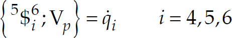
In order to satisfy an algebraic requirement, note that the screw 5$61 is reciprocal to all the screws of the limb 1 and therefore one can obtain

Casting into a matrix-vector form Eqs. (7)–(10), a compact velocity expression is formulated as follows

where
Let

where
The inverse acceleration analysis (IAA) consists of finding the joint acceleration rates of the limbs of the parallel manipulator given the accelerator

where

Therefore the reduced acceleration state
This section finishes with the main purpose of this contribution, the jerk analysis of the artificial spine.
Let
Furthermore, the jerkor can be written in screw form, see Gallardo-Alvarado et al [32], through any of the limbs as follows

where
The inverse jerk analysis (IJA) consists of finding the joint jerk rates of the parallel manipulator given the jerkor
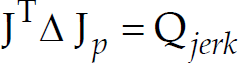
where

Therefore the reduced jerk state
Finally, once the velocity, reduced acceleration and reduced jerk states are computed using the origin of the global reference frame XYZ as the pole, the linear and angular properties of any point attached at the moving platform, for example its geometric centre, are computed by applying the concept of helicoidal vector fields, for details see Gallardo-Alvarado et al (2008c).
The parameters, using hereafter SI units, and generalized coordinates of the numerical example are listed in Table 1.
Parameters of the numerical example

Parameters of the numerical example
With these data the resulting time history of the angular and linear jerks of the moving platform, with respect to the fixed platform, is provided in Fig. 2.

Time history of the forward jerk analysis of the centre of the moving platform.
Please note that, as it was expected, the linear jerk along the Y axis is practically null. Furthermore, in order to avoid singular configurations the considered interval for the time t was
In this work, a novel five-degrees-of-freedom parallel manipulator is proposed for simulating the jerk analysis of the end of the spine. This manipulator brings the following features:
Decoupled architecture, which is a combination of a spherical parallel manipulator with a planar parallel manipulator for controling, respectively, the orientation and position of the moving platform with respect to the fixed platform. Due to the decoupled topology, the forward displacement analysis is presented in a semi-closed form solution. All the feasible locations of one platform, with respect to the other, can be calculated given the five generalized coordinates. Simple and compact expressions for solving the velocity, acceleration and jerk analyses are derived here by applying the concept of reciprocal screws via the Klein form of the Lie algebra e(3) which is isomorphic to the theory of screws. The proposed parallel manipulator is a non-overconstrained parallel manipulator and unlike the parallel manipulators introduced in Zhu et al [25] does not require additional conditions of manufacture.
Finally, a numerical example is provided.
Footnotes
7. Acknowledgement
This work was supported by National Council of Science and Technology, Conacyt, of México.