
Abstract
A novel approach to neural network based tracking-control of robot manipulator including actuator dynamics is proposed by using of backstepping method. A simple two-step backstepping is considered for an n-link robotic system, and a feedforward neural controller is designed at second step where structured and unstructured uncertainties in robot dynamics and actuator model are approximated by this neural controller. Bounds of network reconstruction error and other imprecisions are estimated adaptively and for compensating them, a robust control signal is added and modified. Stability analysis is performed by the Lyapunov direct method and performance efficiency of the proposed controller is justified by the simulations.
Introduction
Highly nonlinearity and high coupling between dynamics are well known characteristics of n-link robot manipulators. These characteristics in company with structured uncertainties caused by model imprecision of link parameters, payload variation, etc., and unstructured uncertainties produced by un-modeled dynamics, such as nonlinear friction and external disturbances make the tracking control of rigid-link manipulators a complicated problem (Spong, M. W. & Vidiasagar, M., 1989). Additionally, one constraint on controlling robots is saturation nonlinearity of actuators which is less considered in controller design for robot manipulators (Fateh, M. M., 2008).
Prominent capabilities of neural networks (NN) such as learning ability and universal approximation property (Funahashi, K. I., 1989) have drawn much attention in control research areas especially in robot control systems (Hunt, K. J., et al., 1992), (Lewis, F. L., et al., 1998).
Systematic design procedure of backstepping methodology makes it satisfactory for designing tracking strategy for large class of state feedback linearizable nonlinear systems (Khalil, K. H., 2001). The most important disadvantages of backstepping approach are that some nonlinearities of the system are needed to be linear in the unknown parameters which may not satisfy in some applications (e.g. modeling the friction in robot manipulators). Also, determining what so called regression matrices is tedious and time consuming task (Kwan, C. & Lewis, F. L., 2000). A robust backstepping controller is designed by (Soltanpour, M. R. & Shafiei, S. E., 2009) for control of robot manipulator in task space. Despite considering uncertainties, the control design procedure has model dependency and some restricting assumptions have been adopted in that respect. On the other hand, in combination with neural network, one can take advantages of both methods and the aforementioned drawbacks of backstepping could be improved. Neural networks with backstepping methodology are widely explored via different manners. Zhang et al. (Zhang, T.; Ge, S. S. & Hang, C. C., 2000) considered strict-feedback nonlinear systems and by utilizing an integral-type Lyapunov function, they designed an adaptive neural network controller. Their approach does not require estimating nonlinearities which may cause singularity problem, but the design procedure is complicated and is difficult to implement practically. On the other hand, a simpler method was proposed in (Li, Y., et. al, 2004) by using of RBF neural networks which can completely avoid the singularity problem. Gong and Yao (Gong, J. Q. & Yao, B., 2001) could generalize the control strategy to systems in semi-strict feedback form that have unmatched model uncertainties. As a more generalized case, nonlinear systems in pure-feedback form were studied by (Wang, D.; & Huang, J., 2002) using adaptive neural networks. As well, in (Zhang, Y., et al., 2000), a stable neural controller was proposed for minimum phase nonlinear systems, not necessarily in strict-feedback form, by backstepping procedure. All of these last five studies were developed for SISO nonlinear systems and are not applicable to n-link robots directly. The MIMO nonlinear systems in strict-feedback form and block-triangular form were studied in (Kwan, C. & Lewis, F. L., 2000) and (Ge, S. S. & Wang, C., 2004), respectively. The input-hidden weights of neural networks in (Kwan, C. & Lewis, F. L., 2000) are assumed to be known and three networks are designed via backstepping for N-DOF rigid-link flexible joint robot. This last case was developed for industrial implementation of coupled motor drives with some modification of stability proof (Kuljaca, O., et al., 2003). As can be seen from foregoing discussion, NN backstepping has been investigated to nonlinear systems in general and not been employed to robot control problems so much.
It is worth mentioning that actuator dynamics carry out a significant role in the complete robot dynamics; and ignoring them may cause detrimental effects, especially in the case of high-velocity moment, highly varying loads, friction, and actuator saturations (Chang, Y. C., et al., 2008), (Chang, Y. C. & Yen, H. M., 2009), (Huang, S. N., et al., 2007), (Wai, R. J. & Chen, P. C., 2006). Since the electrical actuators are highly controllable in comparison with the other one, they are more convenient for driving manipulators. Also, in practical applications, the voltages or currents of the electrical actuators are accessible for applying control commands and consequently, torque-based control design confronts implementation problems where one intends to apply the torque control commands directly to actuators.
Tracking control of n-link robot manipulator actuated by permanent magnet DC motors is aim of this article. In order to use classical backstepping procedure, the system dynamics are put in the outline of error system in simple canonical form. Structured and unstructured uncertainties in robot dynamics and actuator model are considered here. Only one neural network is utilized for NN control part which needs less computing operation than conventional similar methods (Chatlatanagulchai, W., & Meckl, P. H., 2005), (Kwan, C. & Lewis, F. L., 2000) and thus more convenient in implementation viewpoint. The NN weights are updated adaptively and robustifying signal is added such that all the states and signals of the closed loop system are bounded despite unknown parameters. Furthermore, a modification is performed to avoid singularity and chattering problems due to rbustifying added term.
Plant dynamics and problem formulation
The mathematical equations describing electrical and mechanical dynamics of a permanent magnet DC motor are as follows (Spong, M. W. & Vidiasagar, M., 1989):
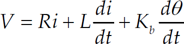
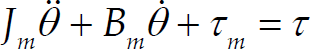

where V is the armature voltage of the motor, R and L are armature equivalent resistance and inductance, respectively, K b is the back electromotive force constant, i is the armature current and θ denotes the rotor position, J m is the total moment of inertia, B m is the damping coefficient, τ m and τ represent the generated motor torque and the load torque, respectively, and K m is the diagonal matrix of motor torque constant.
The dynamical equation of an n-link robot manipulator in the standard form is describing by (Spong, M. W. & Vidiasagar, M., 1989):

where M(q) ∈ Rnxn is the completed inertia matrix, the vectors
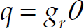
and
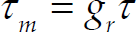
where g r is the diagonal matrix of reduction ratio. In the following, some conventional properties of the robot manipulators and a practical constraint are considered.
Constraint 1
The maximum voltage that joint actuator can supply is V
max
. Therefore, we have:

It should be noted that, the applicable control input for driving robot arm is the armature voltage of the motors, here. So, by using equations (1)–(6) and neglecting inductance (L), because of its tiny amount, the following equation is achieved.

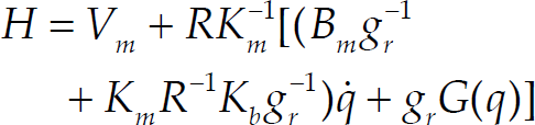
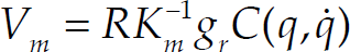
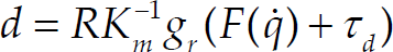
The previous equation can be expressed in a compact form as below.
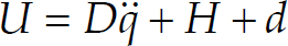
with U = V[volt] is the control command and the other parameters are:

If one considers the desired trajectory which joint position must be held on it as q
d
, then the tracking error of the joint angles can be defined as:

Here, the tracking problem refers to define the control law such that the error e would be driven toward the inside of an arbitrary small region around zero with maintaining the armature voltage within the constraint 1. In the next section this aim will attain.
A key step in designing backstepping controller is to introduce a suitable state space form of the system dynamical equations. Accordingly, we define the error system with states as X1 = e1 and X2 = ė1. From (8) and (13), we have:
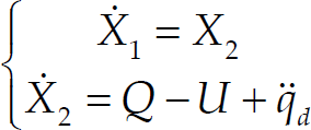
where
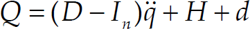
where I
n
is the nxn identity matrix and D, H and d are unknown dynamics. In the first step the virtual control input is considered as:

where μ is a positive constant. If X2 = v then by defining following Lyapunov function one can conclude the exponential stability.

In the second step this virtual control must be realized such that the error term,

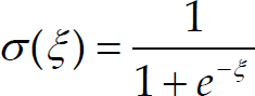
tends to zero in ideal case or to be small as much as possible. Because of the existence of unknown parameters and uncertainties in the second part of equation (14), this realization is not attained straightforward. Controller design for this step is complicated and given in theorem 1. Note that whereas the function Q consists of position angle, velocity and acceleration of robot joints which have continuous variation through time and disturbances which are supposed to be continuous, so the function Q is continuous function. Consequently, according to universal approximation property of neural networks (Hornik, K., et al., 1989), there is a two-layer NN with sufficient number of neurons and sigmoid activation function for hidden layer and linear activation function for output layer such that:

where f(z,V,W) is ideal neural network that can approximate Q with optimum weights V and W and arbitrary small network reconstruction error ɛ in a compact connected set. The sigmoid activation function is used here with definition below:
The input vector z is chosen as:

Succeeding section explains complete controller design and investigates stability content.
From previous section we need control law including NN control part (U
NN
) to approximate unknown nonlinearity Q and appended robust control part (U
r
) to compensate some non-idealities and imprecisions. For this purpose we consider the control law as following.

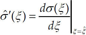
Note that the utilized weights in (20) are optimum and f(z,V,W) is approximated ideally, over there. Estimation of f is accomplished by evaluating W and V by the estimative weights Ŵ and

where

as well, the hidden layer output error for a given x is

Consider the σ(V
T
z) as its Taylor series expansion as (Lewis, F. L., et al. 1998):

where O
h
(·)stands for higher order terms in Taylor series and

Lemma 1
The overall error between optimum function f and its estimation

where

is the uncertain term.
Proof
the proof of this lemma is similar to procedure accomplished for stability proof of theorem 2 in reference (Tang, Y., et al., 2006) and so is omitted here.
The uncertain term ɛ
N
is supposed to be bounded by K as demonstrated below.

where ‖·‖ denotes the two norm. Now, design of the control system is provided in the following theorem.
Theorem 1
Robot manipulator including actuator dynamics represented by equation (8) is considered and the error system is defined by (14). By applying the control input (22) with the robustifying term (32) and together with adaptation laws of NN controller and estimated bound as (33)–(35) and, all signals in control system are bounded and stability of the dynamical system is guaranteed.


where μ, α, β and γ are positive constants that are designing parameters of the control input. Also,
Proof
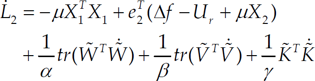
consider the following Lyapunov function candidate

where tr(·) denotes the trace operator and
By using of lemma 1, one can obtain:

Some useful relations for manipulating last tow equations are provided below.
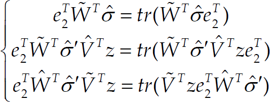
So, using above relations produce

Noting that

and so

substituting (32) and (35) in (41) and adopting (31), yields

Since Λ2 ⩽ 0, the stability in the sense of Lyapunov is guaranteed which implies that

whereas,
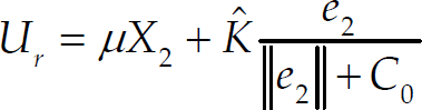
In this section we consider some practical issues and in consequence perform some modifications in our previous design. First, the robust control term in (32) may address singularity problem and lead chattering in control effort. To deal with this difficulty, it can be slightly modified by following equation.
where C0 is a positive constant. The error convergence analysis after this modification is developed below. Consider the (40) as

substituting (35) and (43) in (44) yields

adopting (31) gives
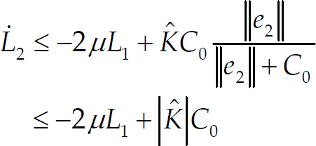
whenever L1 >|
So, our control design is summarizes as following.

with adaptive weights and adaptive bound given by (33)–(35).
Remark 1
If the error leaves the set
Second, note that the input

In order to show the effectiveness of the proposed control method, it is applied to a two-link elbow robot (see Fig. 1) driven by permanent magnet DC motors with the parameters given by (49).


Two-Link Elbow Robot Manipulator
where q i is the angle of joint i, m i is the mass of link i, l i is the total length of link i, l c i is center-of-gravity length of link i, and g = 9.8 m/s2 is gravity acceleration. The detailed parameters of this robot manipulator and permanent magnet DC motor actuators are provided in Table 1 (Wai, R. J. & Chen, P. C., 2006).
Parameters of two-link elbow robot and actuators

According to the actuator manufacturer, the DC motors are supposed to be able to accept input voltages within the following bounds:

The external disturbances that can be external forces are injected into the robotic system, are supposed to have following expression.

Also, the friction term is considered here as:

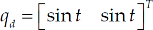
In order to show the effectiveness of proposed controller in tracking of desired trajectory, it is assumed to have sinusoidal shape in this simulation.
The design parameters are set as α = 5, β = 5 and γ = 2. The neural network which is designed here has eight neurons as hidden layer and two neurons as output layer, and its weights are totally initialized at zero. We choose μ = diag{10, 10} and C0 = 0.05. Choosing larger μ and smaller C0 makes the transient response faster but greater μ enlarges the control input and constraint 1 may not satisfy anymore and on the other hand, smaller C0 causes chattering. So there is a tradeoff between favourable response and practical limitations.
In the reminder of this section three simulation cases are carried on. In the first case, the disturbance (51) is injected and the controller with (32) is applied. In the second case, the modified controller is replaced and finally in the third case, the friction term is added.
Simulation 1
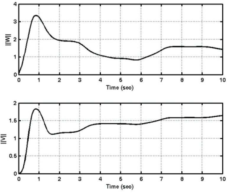
The desired trajectory is depicted in Fig.2 and disturbance is injected at 2 sec during simulation. The vector of tracking errors is shown in Fig.3. So the proposed controller can reject external disturbance and position error of joints are in the small ranges. Because of robust signal structure in control effort (input armature voltage of motors), Fig.4 displays the existence of chattering in input control commands. Fig.5 demonstrates matrix norm of adaptive network weights ‖Ŵ‖ and ‖

Desired input trajectory q d
Tracking error of joints (sim1)

Control commands (sim1)
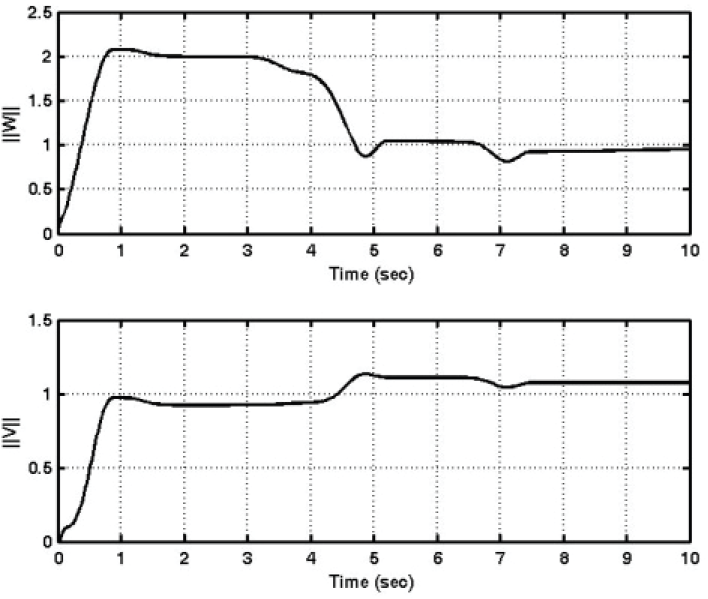
Matrix norm of adaptive weights

NN control effort (sim1)
Simulation 2
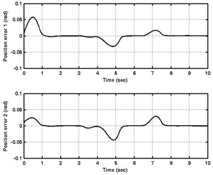
In this case, the modified control law is applied. Vector of tracking errors is illustrated in Fig.7 that is less than [5 5]
T
x10−2 rad. The control effort is shown in Fig.8. Chattering is fully eliminated here and because of inserting disturbance at 2nd sec, the control commands change at this time. Fig.9 displays NN control effort and as demonstrated, the NN outputs are not changed significantly after replacing

Tracking error of joints (sim2)

Control commands (sim2)
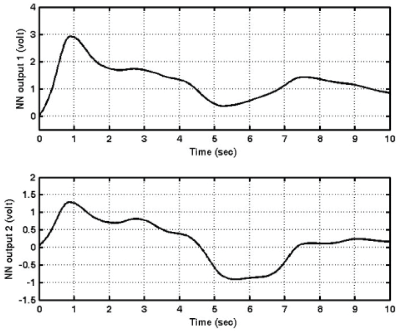
NN control effort (sim2)
Simulation 3
With the purpose of showing robustness of our designed controller against uncertainties and un-modeled dynamics, the friction term (52) is added here. In this case, the vector of tracking errors is shown in Fig.10 and tracking control problem is fulfilled as well. Also Fig.11 displays

Tracking error of joints (sim3)
Matrix norm of adaptive weights

NN control effort (sim3)

Control commands (sim3)
Whenever, fast and high-precision position control is required for a system which has high nonlinearity, unknown parameters and suffers from uncertainties and disturbances, such as robot manipulators, in that case, necessity of designing a developed controller that is robust and has self-learning ability is appeared. For this purpose a robust neural network control using backstepping approach for position tracking of robot manipulators driven by permanent magnet DC motors was addressed in this paper. Backstepping provided the design framework and only one neural network employed for approximating nonlinearities with cooperating of robust control method. Moreover, four major practical aspect of robot manipulator control were considered here, such as actuator dynamics, restriction on input armature voltage of actuators due to saturation of them, friction and uncertainties. In spite of these features, the controller was designed based on Lyapunov stability theory and it could carry out the position control with fast transient and high-precision response, successfully. Finally, three-step simulation results of applying the proposed methodology to an electrically driven two-link elbow robot were provided and they confirmed the success of presented approach.