
Abstract
In this work, we propose a new method for the optimal design and tuning of a Proportional-Integral-Derivative type (PID-type) interval type-2 fuzzy logic controller (IT2 FLC) for Delta parallel robot trajectory tracking control. The presented methodology starts with an optimal design problem of IT2 FLC. A group of IT2 FLCs are obtained by blurring the membership functions using a variable called blurring degree. By comparing the performance of the controllers, the optimal structure of IT2 FLC is obtained. Then, a multi-objective optimization problem is formulated to tune the scaling factors of the PID-type IT2 FLC. The Non-dominated Sorting Genetic Algorithm (NSGA-II) is adopted to solve the constrained nonlinear multi-objective optimization problem. Simulation results of the optimized controller are presented and discussed regarding application in the Delta parallel robot. The proposed method provides an effective way to design and tune the PID-type IT2 FLC with a desired control performance.
1. Introduction
Fuzzy logic controllers have been commonly adopted in many areas of engineering over the last few decades [1–4]. This can be attributed to their linguistic-based structure, which does not need a precise mathematical model of the object and can handle the uncertainty of systems’ information [5–8]. Some researchers [9, 10] have proved that FLCs are more robust and their performance is less sensitive to parametric variations than conventional controllers. H Ying et al. proved that FLC is a nonlinear, variable parameter controller, which can effectively control nonlinear, strong coupling with time-varying structure systems [11].
Due to the closed kinematic structure, Delta robots present better performance in accuracy, rigidity and payload capacity over their serial counterparts. All these advantages make this robot a good platform in many areas of engineering [12–15]. However, the Delta robot system is a kind of nonlinear, strong coupling system with time-varying parameters, and traditional controllers cannot provide a satisfactory control performance. So FLC is a good candidate to control such a robot effectively, something that is much needed in engineering applications.
Generally speaking, three types of fuzzy controllers are widely used in process control systems: PI-, PD- and PID-type FLCs [16]. PI-type FLCs are more commonly used than PD because they can eliminate steady-state errors [17]. PI-type FLCs show satisfactory performance for linear first-order systems, but poor performance for higher-order systems due to their integration operations. For improved performance, PID-type FLCs are preferred [18, 19]. It should be pointed out that for PID-type FLCs, it is difficult to obtain a 3-D rule base since they are beyond the sensing capability of human technicians. To form a PID-type FLC, researchers usually combine the PI- and PD-type FLCs or one PD-type FLC with an integrator and a summation unit at the output [20].
Recently, much work has been done by researchers to apply T2 FLC to many engineering areas [21–25], because this shows better performance than T1 counterparts. The fuzzy logic controller that contains at least one T2 fuzzy set is called T2 FLC. The T2 fuzzy set is characterized by its membership function, which itself is a fuzzy set [26]. The T2 fuzzy sets are three dimensional including primary membership and corresponding secondary membership. The additional uncertainty dimensions provide more degrees of freedom to directly handle dynamic uncertainties, so T2 FLC could achieve better control performance [27]. However, general type-2 FLCs are computationally intensive due to the type-reduction procedures, which restrict their application [28]. To reduce the computational burden, IT2 FLC is considered in this paper. When the secondary membership functions are either zero or one, the T2 FLCs are called IT2 FLCs. This constitutes a significant reduction in computational burden and a simplification of the controller's design process.
A systematic design method for T1 and T2 fuzzy controllers is still an open question. Many efforts have been made to design the controller structure and tune the scaling factors for both T1 and T2 fuzzy controllers [29–32]. However, there is very limited research on the systematic design method for PID-type IT2 FLCs [33–36]. In this study, an optimal design and tuning method was developed for PID-type IT2 FLCs applied to Delta parallel robots’ trajectory tracking control. The proposed method was broken into two steps as follows: i) construct an optimal structure of the IT2 FLC; and ii) tune the scaling factors of the PID-type IT2 FLC. In the first step, only one design parameter was used to design all the fuzzy membership functions of the entire IT2 FLC. This constitutes a significant simplification of the controller's design process. In the second step, a multi-objective problem was carried out to tune the scaling factors of the PID-type IT2 FLC. The genetic algorithm NSGA-II was introduced to solve the multi-objective optimization problem. The effectiveness of the optimized controllers was evaluated on the trajectory tracking control of the Delta parallel robot.
The remainder of this paper is organized as follows. In Section 2, the rigid-body dynamics of the Delta robot is presented. In Section 3, the background review of T2 FLC is provided and the design of the controller's structure is carried out. The multi-objective optimization of the scaling factors of PID-type IT2 FLC is investigated in Section 4. Section 5 presents the simulation results and Section 6 gives the conclusions.
2. System Description of the Delta Parallel Robot
The Delta robot designed at Harbin Institute of Technology is utilized for evaluating the controllers as shown in Figure 1. The Delta robot is a successfully commercialized industrial parallel robot invented by Dr. Clavel in 1985. As illustrated in Figure 2, the Delta robot system consists of three parallel kinematic chains. Each chain goes from the base platform (1 in Figure 2) to the travelling platform (5 in Figure 2), which is driven by a servo motor (2 in Figure 2) on the base platform. Motions of the base platform are transmitted to the travelling platform through the actuating arms (3 in Figure 2) and the passive arms (4 in Figure 2). The passive arms are a parallelogram structure, which ensures the travelling platform remains parallel to the robot base.
Due to the triple symmetrical structure, each chain of the robot can be treated separately. The structure parameters of the Delta robot are defined in Figure 3. We use the index i (

Delta robot designed at Harbin Institute of Technology

Scheme of the Delta robot

Kinematic sketch of the Delta robot
Based on the virtual work principle, the rigid-body dynamic model of the Delta robot can be expressed as:

where
By substituting the dynamic parameters of the Delta robot into Eq.(1), we get:

where
Eq.(2) can be further simplified as:

where


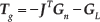
In practice, the Coulomb friction and viscous friction of the robot joints cannot be neglected. Most of the frictions of the Delta robot come from the actuating arm joints and the gear reducers connected to the joints, because they have relatively higher angular velocities and driving torques when the Delta robot is running. There are also frictions in the ball-and-socket passive joints in the passive arms, but since these angular velocities and torques are low, the frictions of the passive joints are negligible. So only the frictions of the actuating joins and the gear reducers are considered in this paper. The rigid-body dynamic equation of the Delta robot considering Coulomb and viscous frictions is obtained:
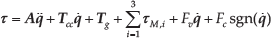
where
3. PID-type IT2 Fuzzy Logic Controller Structure Design for the Delta Parallel Robot
3.1. Type-2 fuzzy logic controller
The block diagram of a typical T2 FLC is depicted in Figure 4. When compared to its T1 FLC counterpart, the major difference between the two controllers is that there is at least one type-2 fuzzy set implemented in the T2 FLC. The character of T2 fuzzy set can overcome the limitations in the ability of T1 fuzzy sets to handle system uncertainties.

The structure of T2 fuzzy logic controller
A typical type-2 fuzzy set

where

The FOU of a T2 fuzzy set is illustrated in Figure 5. Observe that the FOU is bounded from above and below by two T1 fuzzy sets, which are called the upper membership function (UMF) and lower membership function (LMF).

FOU of a T2 fuzzy set
3.2. Interval type-2 fuzzy logic controller
The computational complexity and difficulty in implementation restrict the application of type-2 fuzzy controllers. So the interval type-2 fuzzy logic controller is considered in this paper, for its computational inexpensiveness and ease of implementation. An IT2 fuzzy set

Here, all the secondary membership grades of the IT2 fuzzy set
Consider the rule base of an IT2 FLC consisting of N rules, which can be expressed as:
where
To obtain a crisp output value, the typical computations of an interval type-2 fuzzy logic system usually consist of the following steps.
The crisp input vector with I elements
For rule n, the firing interval (

where * denotes a general t-norm, the product t-norm is adopted in this paper.
Perform type-reduction procedure to get the type-reduced set. In this paper, the centre-of-sets type-reducer is considered. The type-reduced set can be computed as:
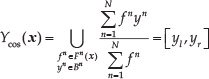
The centroid of the resulting IT2 output fuzzy set is an interval T1 fuzzy set, which can be described by its left and right end points
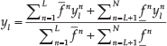
where the switching points L and R can be calculated using the Karnik-Mendel (KM) algorithms [38].
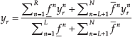
The final crisp output can be computed as:

3.3. The structure design of IT2 FLC for the delta parallel robot
For most fuzzy controllers, the error and its time derivative are usually chosen as the inputs of the controllers. However, it is difficult for the fuzzy PD type controller to remove the steady-state error. For the purpose of improving the performance of the IT2 FLC to handle steady-state error and transient response at the same time, the PID-type IT2 FLC is proposed in this work. A schematic view of the PID-type fuzzy logic control system connected to the robot platform is presented in Figure 6.

Control scheme of the Delta robot system
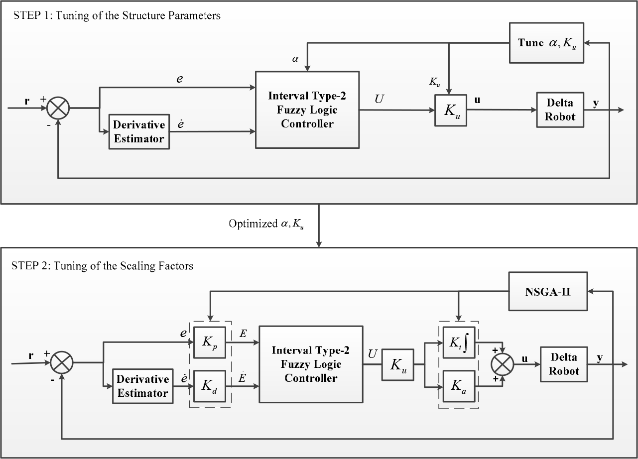
Design and optimization procedure
In this paper, the inputs of the controller were designed using two trapezoidal interval type-2 fuzzy sets for describing the input signal error
where
Due to the complexity of the controller's structure, we designed a two-step procedure to design and optimize the PID-type IT2 FLC as shown in Figure 7. In the first step, the structure of the IT2 FLC is designed without the scaling factors and the integral element. Then, the scaling factors are tuned based on a multi-objective evolutionary algorithm in the second step.
For simplicity, an identical value α is used to design all the input fuzzy membership functions of the entire IT2 FLC, which is called blurring degree. The value α is increased and decreased on the left and right side to determine how much the FOU is to be extended. Figure 8 illustrates the antecedent membership functions of the controller. From Hsiao's work [39], we concluded that changing the width of the consequent sets does not significantly affect the controller's responses, so only the antecedent IT2 fuzzy sets were tuned with the blurring degree during the first step.

Illustrations of the antecedent membership functions for (a) input
To obtain the optimal value of α, the scaling factor
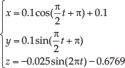
Figure 9 shows the recorded RMSE values of the three joints of the robot with different α and corresponding

The RMSE values of the three joints with variable blurring degrees
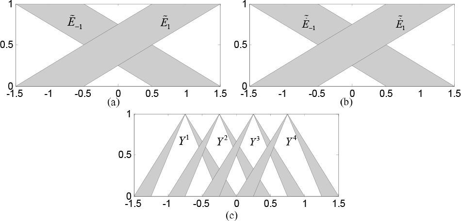
The membership functions: (a) error input sets (b) error derivative input sets (c) output sets
Figure 11 depicts the output control surfaces of different blurring degrees. Due to space limitations, only the most representative three control surfaces are selected. It can be observed that when

The output control surface when: (a) α=0, (b) α=0.5 and (c) α=1
4. Multi-objective Optimization of the Scaling Factors of PID-Type IT2 FLC
4.1. Multi-objective optimization and NSGA-II
The process of optimizing a mathematical problem expressed systematically and simultaneously involving a collection of objective functions is called multi-objective optimization. It is a kind of multiple-criteria decision making and usually has a set of optimal solutions. Mathematically speaking, a multi-objective optimization problem consists of optimizing a vector of functions:

where
The concept used in single-objective optimization problems is usually not applicable in multi-objective optimization problems. For this reason, a class of definitions is introduced in terms of Pareto optimality, according to the following definitions [41]. In terms of minimization of objective functions:
In this paper, we chose a Non-dominated Sorting Genetic Algorithm II (NSGA-II) to find the Pareto solutions for multi-objective optimization. It is a fast non-dominated sorting genetic algorithm with an elitist strategy, especially for multi-objective optimization. Figure 12 shows the process of NSGA-II, and the algorithm used in this work can be stated as:
Generate a uniformly distributed parent population
Using crossover, mutation and selection operations to create an offspring population
Combine the offspring and parent population to form extended population
Sort the extended population based on non-domination.
Choose the best N individuals from the sorting result to form a new parent population
Create the new offspring population
Repeat the steps (3) to (6) until a stopping criterion is met.

Procedure of the NSGA-II algorithm
4.2. Multi-objective optimization of the scaling factors
The goal of multi-objective optimization is to determine the scaling factors of the PID-type IT2 FLC to achieve a desirable control performance. As depicted in Figure 7, there are four scaling factors to be tuned at the second step, so the decision variables of the multi-objective problem can be defined as:

There are two optimization objectives we will take into account simultaneously in NSGA-II: (i) minimization of the position errors of the three joints (
In this paper, integral of time-weighted-absolute-error (ITAE) is adopted as the first objective function to evaluate the position errors of the joints. Since there are three joints of the Delta robot, the first objective function can be defined as:

where
We need

where
The search ranges of the scaling factors are set as:

To improve the computational efficiency, the objective functions should follow the following constrains:

From Eq.(18–22), the multi-objective optimization problem of tuning the scaling factors of the PID-type IT2 FLC can be formulated as follows:
Find a vector

Subject to:

5. Simulation Results and Discussion
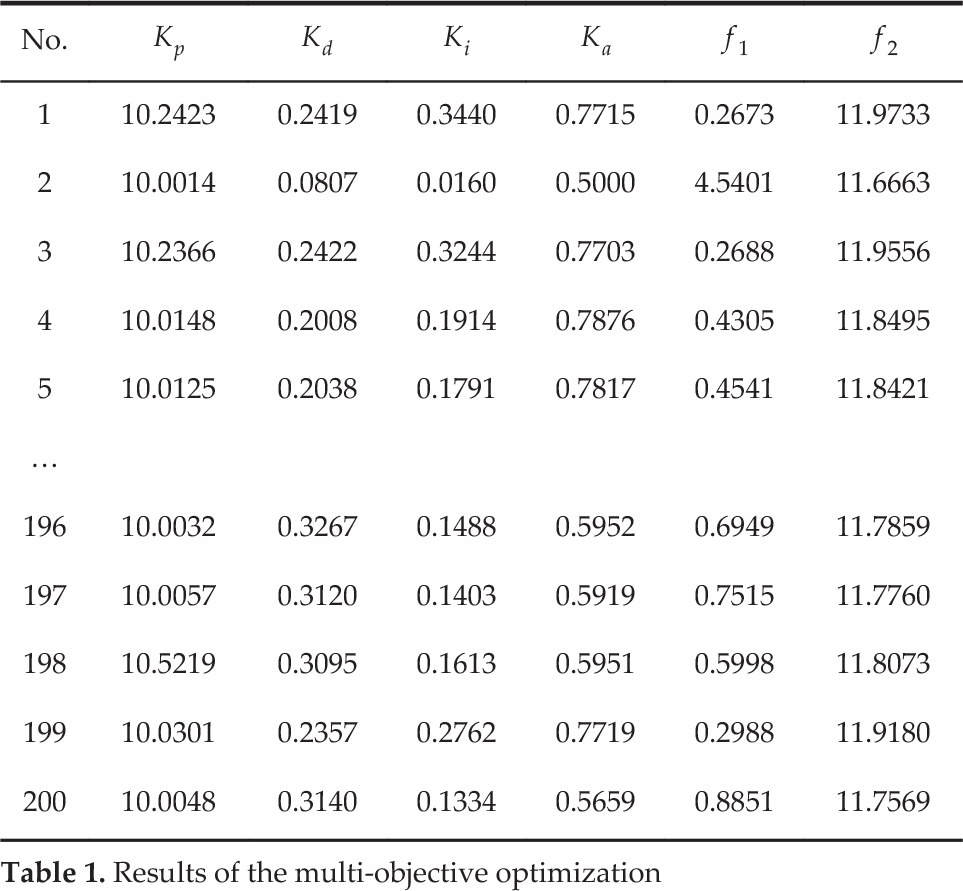
The multi-objective optimization was carried out in a desired trajectory given in Eq.(16). NSGA-II was implemented using MATLAB with the population=200, and generation=200. Figure 13 shows the Pareto front of the multi-objective scaling factors’ optimization results obtained by NSGA-II. Table 1 shows the Pareto optimal solutions of the optimization. It is noticed that there is a trade-off between tracking accuracy and energy consumption. In other words, if we want to have a smaller tracking error, the mean values of the torques will be larger, which means the robot will use more energy to do the same work and vice versa.

The Pareto front obtained by NSGA-II
The scaling factors with minimum
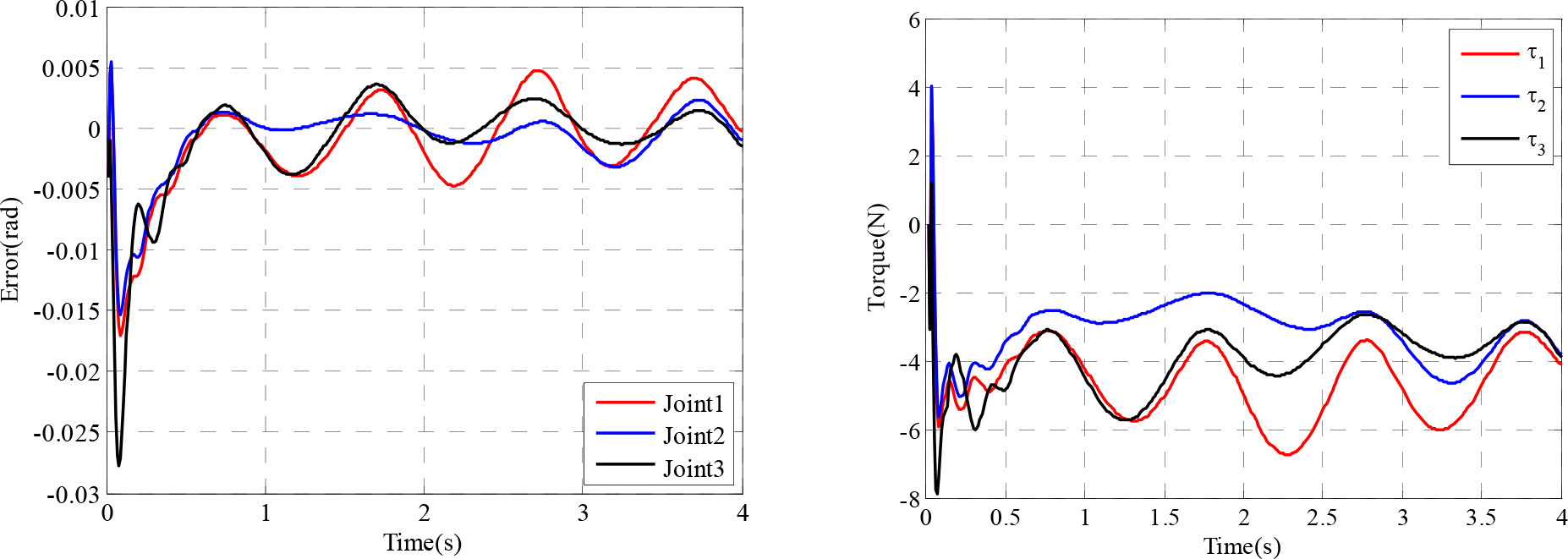
An optimized PID controller used to control the Delta robot [42] is adopted to compare the trajectory tracking control performance with PID-type IT2 FLC proposed in this paper. Here, the Particle Swarm Optimization (PSO) algorithm is used to tune the parameters of the PID controller. The position of each particle is represented by the proportional, integral and derivative gains of the PID controller. The fitness function of the PSO algorithm is chosen the same as in Eq.(19). The response of the Delta robot using an optimized PID controller is presented in Figure 16. From Figure 14–16, we can see that the PID-type IT2 FLC has much higher control precision than the optimized PID controller, but the control torque is slightly larger than its PID counterpart (whether use the scaling factors with minimum
Results of the multi-objective optimization
Results of minimum f1 and f2


Response of the robot with PID type IT2 FLC with minimum f1
Response of the robot with PID-type IT2 FLC with minimum f2

Response of the robot with an optimized PID controller
We can also objectively choose other values in the Pareto solutions according to the design requirements. For example, if we want to get a small trajectory tracking error but not too much average torque during the operation, the solution with a relatively small

Response of the robot with a relatively small f1
6. Conclusions
In this paper, we presented a systematic procedure for optimal design and tuning of a PID-type IT2 FLC. Due to the complexity of the controller's structure, the procedure was broken into two steps. In the first step, a variable called the blurring degree was introduced to find the optimal structure of IT2 FLC. In the second step, based on the two objective functions we have defined, the multi-objective optimization problem of determining the controller's scaling factors was formulated. Then the NSGA-II algorithm was adopted to solve the multi-objective optimization problem. To evaluate the method, we applied it to the problem of trajectory tracking control of Delta parallel robot. The proposed approach gives a good approximation of Pareto optimal solutions, and each solution is a compromise between the two objective functions. Simulation results show that by using different scaling factors obtained in the second step, the PID-type IT2 FLC shows different control behaviours, but all of them provide better control performance than the regularly used PID controller. We believe that the proposed methodology can be a good alternative to solve optimal design problems of similar type IT2 FLCs.
Footnotes
7. Acknowledgements
The authors would like to thank the editors and unnamed reviewers for their valuable comments.