
Abstract
This paper presents the design of a novel variable passive-compliant (VPC) element utilized as a lower-leg implant of a fully electrically driven quadruped robot. It is designed as a slider-piston mechanism which ensures that the force produced during a foot-ground contact is directly perpendicular to the contact surface of an actuated revolute spring. In this way, by altering the stiffness of quadruped legs in a closed-loop manner, the VPC element enables the quadruped robot to adapt to varying terrain characteristics, ensuring a constant hopping frequency over a wide range of terrain-stiffness variations. The designed VPC element and its beneficial characteristics are described in detail. Mathematical relations are formulated that help to describe the influence of the VPC element during vertical hopping of a quadruped robot. The properties of the quadruped research platform with integrated VPC element were verified in simulation and through experiments.
1. Introduction
We witness how four-legged animals perform fast and stable locomotion over a rugged terrain. Therefore, significant effort has been invested by many researchers into transferring the concepts from nature to artificial quadruped robots. It is a known fact that animals can store up to 70% of kinetic energy delivered during landing on elastic tissues [1]. The energy is stored in tendons and ligaments, and is later restored on the next stride. The energy losses are countered by energy introduced by the muscles. The elastic properties of biological legs have many beneficial properties which would otherwise make locomotion in nature less effective. The elastic legs lower the ground-reaction force peak, relieving the stress exerted on the body. They also increase the stride length, allowing faster reaction times to varying ground-surface properties [2]. If legged robots use a common types of actuators (such as electric ones) while performing locomotion with higher effective stiffness, the forces acting on the actuators will have higher peaks. The high impact forces will dissipate energy and increase stress on the mechanical construction of the robot, thus lowering the energy efficiency of the locomotion [3].
It has previously been stated that the leg stiffness of human runners is constant regardless of the surface stiffness [4]. After extensive research on this topic, this theory was disproved. It has been shown that runners in the real word adapt to varying terrain characteristics using various mechanisms. Apart from changing the gait characteristics, runners in nature possess the ability to alter their effective leg stiffness in order to accommodate changes in surface stiffness. This aspect has been researched on human [5] and animal runners. The most important parameter is the vertical effective stiffness which is directly related to the parameters determining the characteristics of locomotion. The changing compliance of the running surface will alter the effective vertical stiffness [6]. In order to maintain the same running characteristics, the runners need to change their leg stiffness in order to minimize effective vertical stiffness deviations [7]. The adjustment of leg stiffness comes naturally to human and animal runners. The choice is mostly determined from the energetic point of view. Many works argue that runners in nature perform their gaits in a way that minimizes energy consumption during locomotion [1, 8].
If we observe hopping in place in order to obtain higher hopping frequencies, the runner's legs need to increase in stiffness [9–11]. In order to accurately describe vertical and horizontal motion during hopping, a particular Spring Loaded Inverted Pendulum (SLIP) model was extensively used. Horizontal movement of the SLIP model takes the touchdown angle which produces the stride length into account. It has been shown that the animals adjust their effective leg stiffness with the square root of the running speed [12], which additionally indicates the importance of incorporating the VPC design.
2. Variable Passive Compliance in Robotics
It is clear that the introduction of compliance in legged robots is necessary from an energetics and control point of view. Today's robots use fixed-value springs to provide compliance during leg contact [13, 14]. The energy accumulated in the compliant elements is partially recovered, while the lost energy from the spring damping is restored by leg actuation on the next stride. The choice of spring stiffness is mainly empirical and does not take into account the varying terrain properties. This makes the cost of travel for these robots larger when changes in the terrain occur [5]. Providing this extra degree of freedom in the form of variable passive compliance could bring today's cutting-edge legged robots one step closer to optimal control on stiffness-varying terrains.
Today's robot-control strategies are mainly based on determining leg trajectories by minimization of energy-related criteria, since this was usually the only way that the energy efficiency of the robot's design could be influenced [15, 16]. Incorporating the VPC elements into the legged robot can serve as an elegant way to add energy-storage flexibility to a robotic platform. Still, the VPC element will be of no use unless it is utilized in the right way. It is mandatory that the leg trajectory works in synergy with the VPC element to result in energy-efficient locomotion.
The majority of cutting-edge legged robots incorporate methods of active compliance tuning (BigDog, HyQ, StarlETH). The active compliance serves an important role in providing natural and stable locomotion but lacks the benefits of energy storage through each stride. The compliance in such systems is usually the result of a control strategy without any passive dynamics. Such solutions require sophisticated high-speed control loops in order to ensure the needed system bandwidth. The use of an electric motor to emulate passive-compliant spring behaviour has been seen in [17]. The uses of such a solution is hard to justify, since electric motors require high-gear ratios to adequately actuate a legged robot. High-gear ratios introduce stiff actuator dynamics and lower the system bandwidth, ultimately leading to high contact forces and a slow system response without the benefit of energy conservation [18].
The studies have shown that introducing the VPC element into robot legs can make the robot's locomotion more adaptable and robust. Some papers address the problem of designing such elements [19]. The VPC element designs mostly utilize torsional springs, series elasticity or structurally controlled variable stiffness. It is evident that the variable passive-compliance benefits were recognized by many researchers who incorporated various VPC designs into robotic platforms [20].
A good example of utilizing the passive compliance in the quadruped robot is shown in [21]. The passive-compliant leg element shares similarity with the approach taken in this work. The spring was dimensioned for a specific case of ensuring a stepping frequency of about 2.5 Hz as suggested by biological research. This work did not address the possibility of adjusting the leg compliance. Another VPC element design is presented in [22]. The design possesses structure controlled-stiffness properties which can be simply adjusted using an integrated actuator. The design shares all the beneficial aspects of the design proposed in this work.
A good example of a robot with structurally variable passive-compliant legs is robot RHex [23]. The design was later altered in [24] to obtain better properties. This approach shares some similarity with the approach presented in this paper. The compliance is generated by the C-shaped element manufactured from aluminium. The varying stiffness is achieved by moving a small aluminium guide along the C leg's diameter using a small DC actuator.
Another leg design shown in [25] shows an effective way to alter spring stiffness. The design is in the form of an articulated leg with two degrees of freedom. The VPC element comprises the fibreglass plates linked to spiral pulleys. By controlling the pretension, the series stiffness can be altered. This design is somewhat complex and introduces common mechanical problems like friction and backlash.
This paper is organized as follows. Section 3 describes the observed quadruped robot with a mounted VPC element, while Section 4 focuses on the newly designed VPC element and its mechanical characteristics. This section states the benefits of the new design in comparison to other previous solutions. In Section 5 we formulate mathematical relations of the SLIP model that identifies the behaviour of the VPC element when used in quadruped-hopping control. In Section 6 we present the obtained simulation results of the quadruped behaviour when hopping on different surfaces. Section 7 presents the experimental set-up and results obtained using the actual hardware that presents the benefits of the new VPC design. Final conclusions and remarks are stated in the last section.
3. Robot Dynarobin
The observed fully electrically driven quadruped robot Dynarobin is shown in Figure 1. Dynarobin has four identical articulated legs
Mechanical characteristics of the robot Dynarobin


Overview of a quadruped research platform
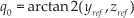
The robot leg and its coordinate systems are depicted in Figure 2. The robot leg is equipped with three revolute joints with respective joint variables


where:

where

Robot leg with a mounted VPC element
4. The VPC Element
In this work, we extend the concept of the variable passive-compliant leg design described in [26] with additional beneficial extensions. The VPC element design in [26] proved to be an adequate option for the simple integration of VPC behaviour into a robot leg. The design relies on structural compliance. The shortcoming of the previous design was the inability to suppress the element movement in non-desirable directions. The previous design made the robot look unstable during locomotion due to the spring deflections in various directions as shown in Figure 3. The element was bending during robot movement which produced less stable locomotion.

Flexion of the previous VPC design due to horizontal forces
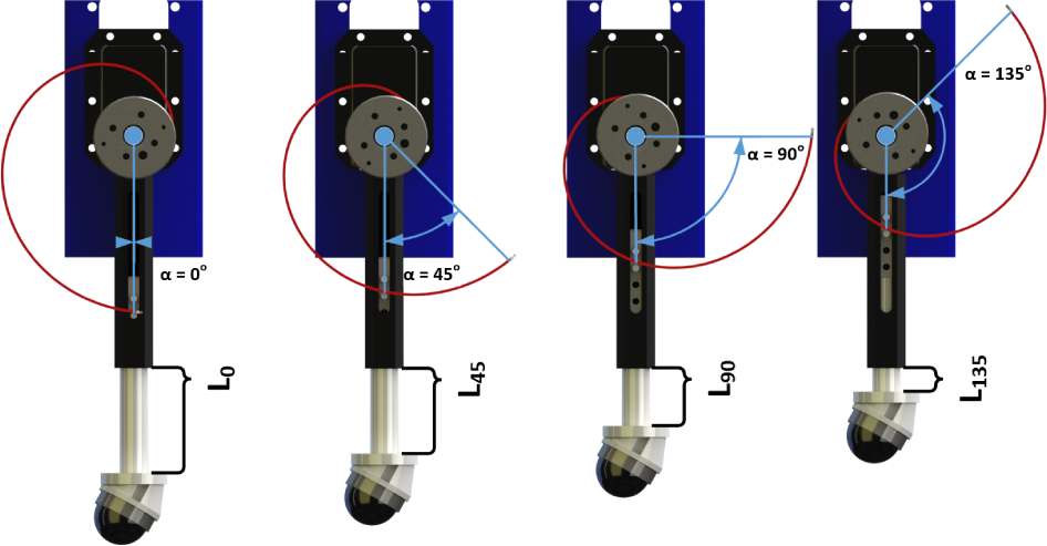
In order to reduce the unwanted behaviour and completely eliminate the compliant motion in other directions, the mechanical design of the variable passive-compliant element was revised. The piston/slider mechanism is built from lightweight ABS plastic, making it durable and easy to produce. The mechanical design consists of the revolute spring, crank and piston mechanism, actuator and a force sensor. The piston transfers the contact force on the contact surface of the revolute spring. The 3D force sensor mounted on the end of the piston mechanism is in direct contact with the ground surface, which allows us to obtain information about the nature of the foot-ground contact. The variable compliance is achieved by rotating the revolute spring with a small actuator.
4.1. Benefits of the new VPC element design
The piston and slider mechanism was utilized as it transfers the contact force in the only desirable direction on the revolute spring. The position of the piston-revolute spring contact is determined by the rotation angle α, which is directly related to the stiffness of the element as shown in Figure 2. The leg was designed with simplicity in mind and we consider the proposed design to be the simplest and most cost-effective solution. A small linear spring is mounted inside the VPC element, which helps the piston to maintain tight contact with the revolute spring, as visible in the VPC cross-section presented in Figure 4. The lowest stiffness value of the linear spring is chosen so that the dynamics of the linear spring does not influence the dynamics of the VPC element.

VPC element cross-section (Left α=0°, Right α=120°)
Changes to the α angle add almost no additional inertia to the leg, which is a desirable effect. A small amount of inertia is added in the form of piston extension by Lα which adds additional complexity to the inverse kinematic calculation as shown in Figure 5. Since the inertia added by the extension Lα is small in comparison to the lower-leg part, this effect can be neglected.
VPC element while changing the α angle
The previous design required a high-torque DC motor to maintain the spiral joint's position. The forces that were produced during contact produced significant torque on the motor shaft. The DC motors that were initially used to position the spiral joint were unable to ensure correct positioning during the contact phase. Apart from incorrect positioning that produced variation in the VPC's stiffness, the greater problem was the energy waste produced by the motor while trying to correctly position the spiral joint.
The benefit of the new design is that almost no power is required to maintain the selected stiffness. It is necessary to keep the α angle fixed but, since the force is acting in the direction of the motor crank, the forces acting on the motor are minimal. The other benefit is that the leg stiffness is independent of the external load.
During experiments with a single leg in the previous work [26], an additional problem was identified. The previous VPC element was unable to produce constant hopping in one place since the contact surface of the revolute spring was slightly curved. The curved contact surface produced horizontal forces which propelled the leg forwards. This problem was solved at the time by slightly rotating the spiral joint during contact. This slight rotation compensated for the leg's movement and enabled the leg to hop in one place. Ultimately, this solution resulted in the additional wastage of energy. The new leg design completely eliminates this effect, making the previous compensation unnecessary and thus improving energy efficiency.
One of the side benefits of the new robot leg design is the ability to install force sensors in the robot's feet, which was previously impossible. The contact point with the ground surface in the previous leg design was located on the outer diameter surface of the revolute spring. Thus, the contact point varied the angle α. The new design strictly defines the location of the contact point, allowing the mounting of the force sensors to measure the nature of the contact with the ground surface. The design perfectly suits the mounting of the small Optoforce sensors that provide three axis force sensing [27].
The added slider and piston mechanism can take some additional concerns into account. For example, the friction between the slider and a piston is one such concern that can be reduced by precise manufacturing of the part and use of adequate lubrication methods. Additionally, by adding the mass of a piston, manufactured from lightweight plastic and weighing approximately 30 g, additional dynamics are introduced. On the other hand, since the piston segment is small and light in comparison with the rest of the mechanism, its dynamics are hard to notice.
In order to provide realistic and accurate inputs for further evaluation of design through mathematical modelling and simulation, the revolute spring stiffness k, damping d and length Lα had to be identified. The identification of the stiffness coefficient was performed on the industrial-strength tester Tenso lab 3000, by vertically pushing the spiral spring for a fixed displacement length and measuring the produced force on a load cell. The force output was repeatedly measured while varying the position of the contact on the outer diameter of the revolute spring, ultimately forming the stiffness-varying characteristics. The damping of the revolute spring was determined by identifying the energy lost, by calculating the difference in potential energy between two consecutive hops during a drop test. The tests were repeated for the various angles of α and the data points were recorded. The measured parameters for the stiffness and damping are shown in Figures 6 and 7, respectively. In order to obtain a continuous distribution of stiffness and damping across a range of α values, the following polynomials were fitted:


The length Lα was calculated by measurements obtained through a CAD model, resulting in the following interpolated curve:

The identification procedure is presented in [26].
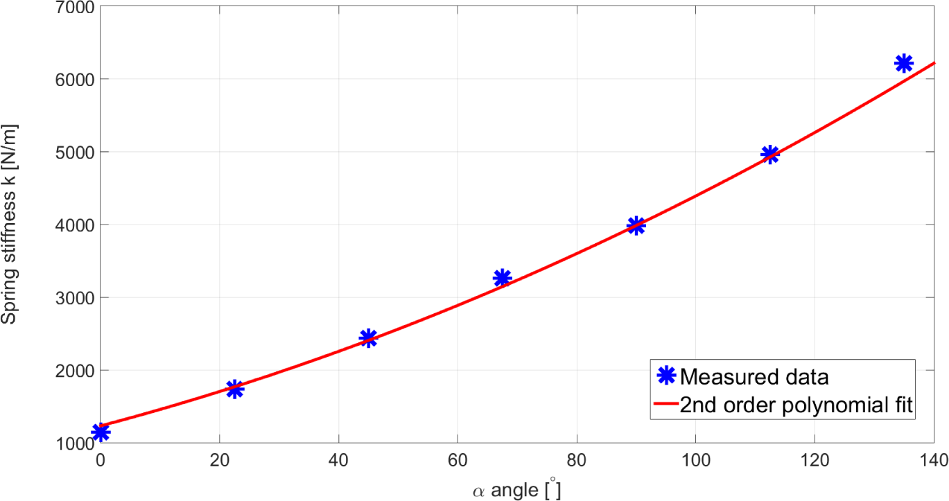
Spiral spring identification results for stiffness k

Spiral spring identification results for damping d
4.2. Compliant parameters’ kinematic transformation
The articulated leg mechanism and its compliant behaviour can be simplified to a virtual leg with a spring and damper connecting the foot and the robot's hip joint. In order to discover the relations that connect the effective spring stiffness and damping of the virtual leg and the identified stiffness and damping of the robot leg with the VPC element, the previously mentioned simulation model was used.
The virtual leg concept was introduced in [28] and it has enabled various authors to simplify the analysis of multi-joint leg compositions to that of a single spring. We utilize the same concept in order to introduce the effective stiffness and damping parameters for the leg mechanism. The effective spring stiffness
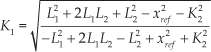
Since the piston is not perpendicular to the contact surface, the ground reaction force is not directly transferred in the direction of the VPC element. The compliance of the leg mechanism (stiffness and damping) will be influenced by the nature of the contact with the ground. Assuming that the foot's position is located directly beneath the hip joint (
The effective leg damping

VPC stiffness while changing α and z ref
5. Vertical SLIP Model of a Robot Leg with a VPC Element
The SLIP model was introduced in order to describe the locomotion observed in nature [29]. It has been widely used in simplifying the mathematical description of walking robotic systems while focusing on the important parameters that influence locomotion. The SLIP model was initially formulated on the mass-spring system, covering in-place hopping and locomotion scenarios. The SLIP model describes the energy transfer through swing and stance phases which lead to information like stride length, stride frequency, etc.
The initial SLIP model did not consider the damping factor which contributes to energy losses in the observed system. It was later extended to describe a more realistic and practical situation where energy has to be introduced in the system to provide constant locomotion. Animals and humans use their muscles to recover the energy lost during each stride. Some of the energy is stored and restored on each step by utilizing the natural passive-compliant elements such as tendons and muscles. It is argued that certain animals can recover up to 50% of energy at each step, thus reducing their cost of travel (COT) [30, 31].
In this paper, we observe the robot's motion in a vertical direction, simplifying the problem to one dimension. During the hopping, the robot exchanges ground and aerial phases. The ground phase is composed of the spring compression and decompression phases. The mathematical description of the observed hopping motion is formulated in this section.
During the aerial phase, the robot is acting as a free body affected by gravity, and its dynamics are simply modelled using the following dynamical equation:

where za denotes the position of the point mass in the aerial phase. During the stance phase, the robot is behaving according to its dynamics. The flight time ta is computed as follows:

where
5.1. Compression phase
Leg movement in the vertical direction during the compression phase is described by the following equation:

where zs denotes the position of the point mass in the stance phase. The effective stiffness

The ground stiffness

The solution to the equation (7) is obtained by assuming that we search for a general oscillatory-damping solution. The system will exhibit oscillatory behaviour if the following condition is satisfied:

Finally, we can write the solution to the dynamics of the compression phase. The solution is composed of the damped-periodical and forcing term:

where the following parameter compositions are identified:
Damping coefficient
Natural frequency
Damped frequency
By inserting the initial conditions

where
The end of the compression phase is determined by the time tb, denoted the bottom time instant at which the speed

Inserting condition (13) into equation (11b) produces the following result:

The maximum spring compression occurs when the vertical velocity during the stance phase reaches zero. This defines the moment of actuation in order to regenerate the depleted energy before the next hop. Referring to (11b), the position of the leg at the maximum compression is defined by:

5.2. Energy loss due to damping
The damping losses are obtainable through assessing the loss of the kinetic energy Ek during one contact cycle of the leg hopping. The contact cycle has a duration

To observe the un-actuated hopping dynamics of a quadruped robot, we can employ the dynamic equations (7) for the full stance length

Due to the transcendental character of (17), the exact closed-form solution for the lift-off time

The lift-off time is set to be equal to the time of the maximum compression, which is uniquely defined for the lossy SLIP model according to the equation (14). The work presented in [33] follows a similar idea by utilizing a Newton-Raphson method to find an approximate solution
Since no measure or comparison between the two approaches has been presented, we will derive the solution using the method presented in [32]. We can rewrite the equation (17) using (18) in the following way:
The final approximate analytical solution for the lift-off time is available through algebraic and trigonometric manipulation:

where

which is a function of the touchdown velocity

5.3. Decompression phase
Introduction of the damping effect requires a way to introduce energy into the system in order to obtain a constant hopping frequency. Even though this extension adds additional realistic considerations into account, it also adds a fair amount of complexity to the calculation, making the lossy SLIP model a not so widely adopted term [34]. Most authors utilize the SLIP model in its simplest form, leaving energy renewal as a problem of practical implementation [35]. Papers that observe the injection of energy to counter the system losses tend to rely on single joint mechanisms with controllable torque [36] or active linear springs in a series [37], and often make compromises in the form of crude approximations in order to obtain an analytical solution for the apex return map. One such approximation we have shown in the calculation of the lift-off time
In order to compensate for energy losses due to the damping effect, the energy stored in the compressed spring is returned to the system by leg actuation during the decompression phase in the form of the force Fu. The goal is to restore enough energy to achieve a constant hopping frequency. Since the stance phase is composed of compression and decompression phases with different dynamics, the assumption used in Section 5.2 (

where
Bearing the stated assumption in mind, we describe the motion of the robot in the decompression phase using the following dynamical equation:

where Fu is the force exerted by the leg actuation starting from the time of the maximum VPC element compression. The solution is written in the following form:

where initial conditions


where
The lift-off time

The lift-off speed is calculated by the terminal condition:
5.4. Leg actuation strategy and energy introduction
The kinematic reference

where z0 denotes the leg equilibrium position (typically in the middle of the z axis workspace) and
Steady-state hopping cycle of a quadruped robot
The robot joints

where the xf, zf pair denotes the position of the foot's contact point when observed from the hip coordinate system. Next, we calculate the Jacobian matrix. The Jacobian of the serial manipulator is formulated as follows:

The calculated Jacobian matrix relates the angular velocities of the joints

By assuming that the robot's foot is in contact with the ground, the torque produced by the leg actuators is transferred to the ground, producing the equivalent reaction in the form of the Ground Reaction Force (GRF) which is responsible for pushing the robot's leg off the ground. The GRF assumes a negative direction to the force produced by the robot's foot

We rearrange the previously stated equation to observe the influence of the joint torques on the foot's force:

The smart DC actuators that actuate the robot's joints contain the internal position and velocity-control loops to relieve the supervising circuit of high-speed computation and communication. Since no information of the internal structure and the actuators is available, they were modelled using a black-box approach. The response of the actuator position q for a given reference position

For a maximum velocity reference and actuator voltage
The actuator position response for the step input of magnitude

Since we observe the robot's vertical hopping motion, the foot trajectory will follow a straight line trajectory along the negative z axis to generate vertical force Fu on the contact surface. Since the foot's position is being controlled through the use of inverse kinematic equations (1), the
The total energy introduced in the system as a result of the leg actuation can be calculated as follows:

where the time tc denotes the length of the contact. Even though the introduced energy is equivalent when it is assessed from the joint or foot space, we transform the work to the foot space in order to clearly identify the terms that contribute to the energy introduced in the negative z direction (which would otherwise be hard to obtain). Since the vertical hopping is observed, we only isolate the terms related to the vertical foot-force component Fz that introduces energy

Under the assumption that the torques delivered by the DC motors are constant at given velocity
Apart from the foot trajectory and actuator characteristics, the amount of energy introduced in the system is mostly dependent on the duration of the contact interval tc. Shorter contact times that arise due to increasing stiffness of the VPC element (as angle α increases) or the surface stiffness, result in less time available to transfer the energy into the system, ultimately leading to the loss of the hopping motion.
5.5. Additional relations
Constant hopping will eventually be achieved as long as the energy

Energy balance is obtained by reaching a steady hopping state after equalizing the introduced and lost energy in one stride cycle, which is mostly dependent on the capabilities of the quadruped actuators. Achievement of steady hopping over time means that the touchdown and lift-off speeds need to be equal:

Now we can formulate the expression to calculate the lift-off speed of the robot during steady hops. We start by inserting (15) into (31), and end by obtaining an equation relating the touchdown speed
Stance is the phase in which the leg is in contact with the ground. The stance time equals the sum of the compression time tb and decompression time

Now we can rewrite (42) using (15) and (31):
Taking into account (16), the solution depends only on the touchdown velocity

6. Hopping on a Surface while Changing Leg Stiffness
Since the quadruped can adjust its leg stiffness, it is evident that we can achieve different stride frequencies by changing the angle α of the VPC element. We utilize the computed equations to show how the stride frequency

Hopping frequency variations with changes of angle α
The analysis of system responses shows that the robot can achieve different stride frequencies ranging from
Following from the derived equation (43), the change in the exerted force Fu will influence the hopping frequency. This is an expected behaviour since the increase in the exerted force results in larger apex heights, thus prolonging the hopping period. The effect of increasing Fu on the hopping frequency and apex heights for fixed surface characteristics

Hopping frequency variations, with changes in exerted force F u for surface stiffness k surf =3000 [N/m]
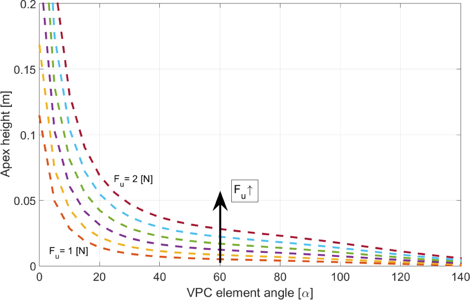
Apex height variations, with changes in exerted force F u for surface stiffness k surf =3000 [N/m]
We can use the computed relations to control the hopping frequency of a quadruped robot upon the sudden change of terrain characteristics. The plot shown in Figure 13 shows the change of stance time with varying terrain characteristics. It can be seen that some combinations of ground surface and leg stiffness do not produce harmonic oscillations. The stance time can be easily calculated by measuring the time of the foot and the ground's contact. Under the known leg stiffness, the change in terrain characteristics will influence the change in the stance time ts, which can be used to calculate the α position needed in order to compensate for the disturbance more quickly. An example is presented in [26, 39], but the controller design for the purposes of terrain adaptation goes beyond the scope of this work.

The change of stance time with changes of angle α and varying terrain stiffness
Besides energy storage characteristics, the additional benefit of the newly designed VPC element is the ability to vary and adapt the quadruped hopping frequency which is otherwise affected by changes to ground surface stiffness.
7. Experimental Results
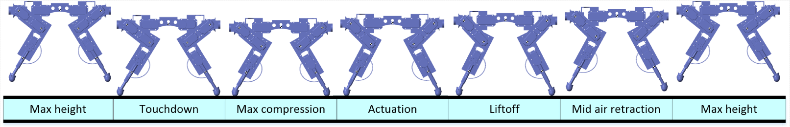
In order to evaluate the beneficial aspect of the newly designed quadruped legs with VPC elements, we performed a set of experiments to compare the previous [26] and current design of the VPC element. The benefit of the new VPC design is that it provides a more stable hopping cycle by eliminating the spiral spring flexion in non-desirable directions, as shown in Figure 3, allowing the robot to hop continuously in one place. An example of the quadruped hopping motion with the newly designed VPC elements is depicted in Figure 14.

Characteristic time instances of a hopping motion cycle of the quadruped robot with the new VPC feet design
7.1. Hardware set-up
The hardware set-up for the experimental validation of the observed quadruped robot is shown in Figure 15. Robot joints are controlled using a specially designed Motor Controller Board (MCB), which allows parallel communication with all robot leg actuators, ensuring synchronous and fast control intervals. The MCB is able to achieve a millisecond control interval with all 18 actuators by separating the communication for each leg and the spine. The use of a Direct Memory Access (DMA) peripheral emulates true parallelism in a single core processor, allowing for rapid message exchange.

Hardware set-up for experimental validation
The MCB is connected to a 4-core ARM On Board Computer (OBC) running Linux via a USB port. The autonomy of the quadruped is ensured with battery packs and a Wi-Fi network link that communicates with an operator PC. Even though the robot's hardware offers full autonomy, the experiments were performed by powering the robot from the laboratory supply in order to ensure equal conditions for all experiments. The system operates under the Robot Operating System (ROS) [40], allowing for a continuous stream of force and visual feedback, joint positions and AHRS data for synchronous logging.
The robot is controlled using the PC while the robot's position and orientation is tracked using an Optitrack motion-capture system [41]. The tracking data are available on the ROS network for logging purposes.
7.2. Hopping stability in an open loop
We have evaluated the effectiveness of the new design by performing an open-loop hopping cycle, and recording the position and orientation of the hopping quadruped in real time. The experiments were performed for both the new and previous VPC design and for three different α values (0°, 90°, 140°). Only the open-loop hopping was performed since the previous design of the VPC element provided no feedback of the foot's contact force. The robot was placed on the medium compliant rectangular hopping surface with dimensions

Experiment set-up for open-loop hopping
The new and previous designs were evaluated by tracking the quadruped's position while hopping in place using three different α values. For this purpose, a rectangular workspace shown in Figure 16 was prepared, with its centroid placed at

Robot position changes during hopping in place with two VPC element designs and various α values (0°, 90°, 140°)
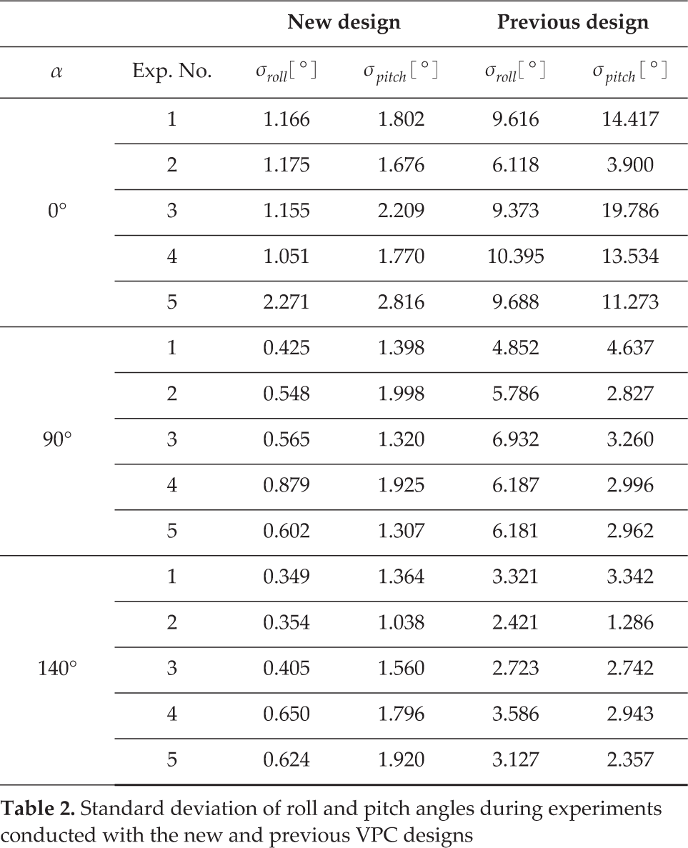
Hopping stability is also observed through the standard deviation of the quadruped roll
Standard deviation of roll and pitch angles during experiments conducted with the new and previous VPC designs
8. Conclusion
In this paper, we describe the beneficial aspects and mathematically formulated behaviour of a new variable passive-compliant element design intended to be used in quadruped control. The newly designed VPC element is a significant improvement over the previous designs. The new design is simple to manufacture and control, while having the benefits of low added inertia, and virtually no added power consumption is needed to maintain the desired stiffness. The lower-leg implant in the form of a slider and a piston mechanism eliminates the compliant motion in non-desirable directions, ultimately increasing the stability of the quadruped's locomotion cycle.
The benefits of the new design were observed in simulation through a typical application scenario of a quadruped robot hopping in place on a stiffness-varying terrain. We have formulated a vertical hopping SLIP model representation of the quadruped, with the VPC elements built into each robot leg. A thorough mathematical analysis based on study of energy relations and hopping dynamics was performed, in order to show how the VPC element can be used to vary the quadruped hopping frequency in order to compensate for the frequency change due to the influence of varying terrain characteristics. Future work will be focused on utilization of the VPC element and formulated model to ensure a closed-loop control of the hopping frequency while controlling the stiffness of the VPC element. Additionally, the extension of a SLIP model to account for horizontal movement will be studied in order to better respond to the influence of uneven mass distribution during robotic motion on uneven terrains, and it will be prepared for additional experimental validation.