
Abstract
With their constant perspective and large magnification in the working distance, double-sided telecentric lenses have been widely used in machine-vision applications. This paper puts forward a flexible calibration approach for the double-sided telecentric camera. Based on an orthographic projection model considering the major sources of lens distortions, a two-step calibration procedure is proposed. In this approach, the camera parameters apart from the lens distortions are achieved by a closed-form solution. Then a double non-linear optimization is performed to refine all the parameters, including the distortion coefficients and distortion centre. In addition, to achieve a flexible calibration procedure, the calibration pattern used is a cheap print product rather than a professional customized calibration pattern. Simulation and real-world experiments are performed to validate the performance of the proposed calibration approach. In addition, the comparison experiments between the print calibration pattern and professional calibration pattern are carried out, and the accuracy of calibration results are at the same level.
Keywords
Introduction
Double-sided telecentric lenses have been widely used in many machine-vision applications such as noncontact measurement and inspection systems [1–3]. The principal scheme of a double-sided telecentric lens is shown in Figure 1. Unlike the perspective projection of the pinhole camera model, double-sided telecentric lenses provide purely orthographic projections of scene points by locating an aperture stop at the focal point of a lens [4]. Thus, these lenses provide constant perspective and a large magnification depth of field. This property makes it easier to measure or compare physical lengths of objects independently from the depths of the objects from the camera [5]. For this reason, they are often well suited for gauging and a variety of other demanding machine vision applications [6–8].

The schematic diagram of light path in double-sided telecentric lenses
Generally, camera calibration is an essential part of metric information [9, 10]. Therefore, the calibration of a telecentric camera is essential for its optical measurement application. The camera calibration for a pinhole model is widely discussed due to its important role in optical measurement, and many calibration methods have been proposed. Tsai proposes a two-step calibration technique considering radial lens distortion [11]. Weng presents a camera model with three types of distortion in the calibration technology [12]. The flexible camera calibration method based on a 2D pattern is proposed by Zhang [13]. There are also calibration methods based on the optical method [14], camera motion [15], structure light [16], and even a star pattern [17]. However, these calibration methods are based on perspective projection in the pinhole camera model, which is not available for telecentric camera calibration.
For telecentric camera calibration, Zhu provides a linear fitting calibration method [18], which is able to achieve the intrinsic parameters for the distortion-free telecentric camera. Li develops a two-step method to calibrate telecentric lenses without considering the ambiguity of extrinsic parameters [19]. The experimental results show that thin-prism distortion should not be ignored, which differs in a traditional perspective camera. Chen proposed an effective calibration method for a telecentric camera in an object space, considering lens distortion [20]. In this solution, the problem of sign ambiguity from the planar object-based calibration technique is successfully solved. However, the four elements of the truncated extrinsic attitude matrices of the camera have been adopted in the non-linear refinement, instead of the independent variable of attitude description. Further, it is assumed that the centre of distortion is known as the image centre in the above literature, but telecentric lenses perform parallel projection and there is no projection centre; however, this is not a safe assumption in general [21]. Experiments carried out by Richard Hartley demonstrated that the centre of distortion may be significantly displaced from the centre of the image, or the principal point of the camera [22].
A flexible camera calibration method for telecentric lenses is proposed in this paper. In this method, a cheap print product replaces the professional customized calibration pattern to achieve a flexible calibration procedure. With the pattern and corresponding algorithm, telecentric camera parameters are all calibrated, including the rotation matrix, translation vector, effective magnification, lens distortion and distortion centre. In addition, the independent variables of attitude description by Rodrigues's formula have been adopted in the non-linear refinement process. The concrete method is as follows:
Based on the orthographic projection model, the calibration procedure is divided into two steps. In the first, the homographic matrix estimated from the imaging equation is used to obtain an initial value of camera parameters with the distortion-free telecentric camera model. Then, a planar pattern with an additional stage is used to avoid the ambiguity of extrinsic parameters. In the second step, considering the accuracy of calibration pattern used in the work, a non-linear optimization is carried out first to obtain more reliable data for the calibration pattern. Then another non-linear optimization is applied for all parameter estimations including the lens distortion and its centre. As the optimization is carried out for all parameters, a refined result is achieved.
The rest of the paper is organized as follows. The double-sided telecentric camera model, including distortion-free telecentric camera model and lens distortion model, is presented in Section 2. The calibration theory and method in detail are in Section 3. Section 4 provides results of computer simulation and real-world experiments, and the comparison experiments are also presented. Section 5 is the conclusion of this paper.
Distortion-free telecentric camera model
The imaging model of a camera with a double-sided telecentric lens can be illustrated by Figure 2. (x w , y w , z w ) and (x c , y c , z c ) are the 3D coordinates of the object point P in the 3D world coordinate system and camera coordinate system, respectively. (u, v) is the image coordinate of P(x c , y c , z c ) in pixels. The projection of an arbitrary point P to the undistorted image plane in pixel units is expressed as follows [19]:

where M is the effective magnification of the double-sided telecentric lens, and (u0, v0) is the coordinate of the image plane centre. d u and d v denote the pixel pitches in u and v directions, respectively.
Suppose that R and t are the rotation matrix and translation vector respectively, which relate the world coordinate system to the camera coordinate system, and the relationship between the world and camera coordinate systems can be described as:

Combining Eq. (1) and Eq. (2), the orthographic projection of double-sided telecentric lenses is expressed by the equation:

Unlike the pinhole camera model, there is no arbitrary scale factor on the left side of Eq. (3) due to the orthographic projection of the double-sided telecentric lens. The detailed derivation process of Eq. (1)–(3) is described in reference [19].

The schematic diagram of imaging with double-sided telecentric lens camera
As a result of several types of imperfections in design and assembly, lens distortions are inevitable and the expressions in Eq. (3) do not always hold true. There has already been research on the physical nature of the distortion of optical systems [23, 24], which depends on the distance of the object from the optical system. Although the distortions of double-sided telecentric lenses are small compared to those of other lenses, accurately identifying the distortion model is also absolutely necessary for telecentric lenses with high measuring accuracy [20].
Similar to an ordinary lens modelled by pinhole perspective projection, the distortions in the telecentric lens can be divided into radial and tangential distortions. Hence, according to Brown's model [25] distortions are given by:

where u and v are the non-observable and distortion-free image coordinates, while u' and v' are the observable coordinates with distortion, and
Generally, there are 11 calibration parameters in the double-sided telecentric camera models presented; five are for extrinsic parameters (the Euler angles yaw, pitch, and tilt for rotation R, the two components t
1
, t
2
for the translation vector
Inspired by Zhang [13], a planar board with control points is used to achieve the intrinsic and extrinsic parameters of the camera in this section. To allow precise calibration, the pattern should be planar within a certain degree in the world coordinate system [26].
Estimation of the homographic matrix
Without a loss of generality, we assume the calibration pattern lies on Z = 0 of the world coordinate system. Therefore, as Eq. (3) can be written as:

Suppose that h ij , is the ith row and jth column element of homographic matrix H. According to Eq. (5), the following equation can be achieved:
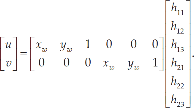
Thus, the elements of homographic matrix H can be easily computed by using the DLT algorithm [27].
With the orthogonality of the rotation matrix R, we have:

Besides, rotation matrix R is unitary, so we can quickly obtain:
Thus, Eq. (9) can be achieved by substituting Eq. (8) into Eq. (7):

Squared on both sides of the Eq. (9), we have:

Suppose that M/d u = M/d v = m, combining Eq. (3) and Eq. (10), and the following equation can be achieved:

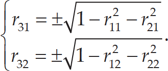
Generally, there are two non-negative roots for Eq. (11). This ambiguous problem can be solved easily by the conditions of
Once m is known, the truncated translation

Obviously, (u0, v0) and
On the other hand, the elements in the upper left 2×2 submatrix of the rotation matrix R for each image can be directly achieved from Eq. (3). Then, the remaining matrix elements can be obtained from Eqs. (8) and (13) since rotation matrix R is unitary and orthogonal.
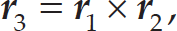
where

According to reference [20], r13 and r23 recovered from Eq. (13) may not precisely satisfy the orthogonality of R because of the noise effect, but their signs are all perfectly disambiguated.
For a distortion-free telecentric camera, we can obtain the closed-form solution of its parameters with only one captured image from Section 3.2. However, the lens distortions are inevitable, as mentioned previously. Thus, a non-linear optimization is performed to refine the all camera parameters considering lens distortion, which is a common step in camera calibration. Nevertheless, the calibration pattern used in the work is a cheap print product to achieve flexible calibration, and the accuracy of print product is not usually enough for camera calibration. Thus, to achieve higher calibration accuracy, a non-linear optimization for the coordinates of control points on calibration pattern is carried out first with bundle adjustment of images observed from different orientations and locations.
The optimization is put into effect by minimizing the following function F:

where p
i
is the image coordinate of
The second non-linear optimization is performed to refine all camera parameters considering lens distortion. The optimization function is as follows:

where
The introduction of double non-linear optimization algorithm

Computer simulations and real-world experiments have been used to verify the proposed method. The details of simulations and experiments are shown in this section.
Computer simulations
In the computer simulations, the camera and telecentric lens parameters are set as the same as the standard parameters in real-world experiments, see more details in Section 4.2. The calibration pattern is made by 88 control points (11 × 8). The capture distance is the working distance of the telecentric lenses. Twelve pictures are taken in the simulation with the Euler angles changing randomly.
Gaussian white noise with a mean of 0 and standard deviation σ are added to the control points. The value of σ changes from 0.1 to 1.0 pixels. For each value of σ in the simulation, the calibration procedure is run 100 times and the statistical results are shown in Table 1 and Figure 3.
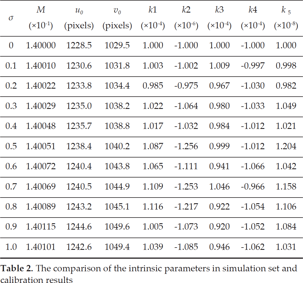
As shown in the Table 2, the intrinsic parameters set and the calibration results of intrinsic parameters are listed, and the calibration results fit the simulation set well. The error variation of intrinsic parameters is not obvious with the noise strength rise. It is suggested that the method proposed is effective in calibrating intrinsic parameters.
In the figure, the lines show the error variation of extrinsic parameters with the increase of σ, and the means of reprojection errors are also presented. As the results suggest, there is a rising trend for errors of extrinsic parameters and a reprojection error with the increase of σ. However, the errors of extrinsic parameters are low in all simulations, and the means of reprojection errors in both two directions are refined within the noise strength. In addition, the error of tilt is larger than the other two Euler angles in Figure 3(a). The explanation is that tilt expresses the roll here, and the estimation accuracies for the yaw and pitch have a higher precision compared with that of the roll for photogrammetry [28].
The comparison of the intrinsic parameters in simulation set and calibration results
The comparison of the intrinsic parameters in simulation set and calibration results
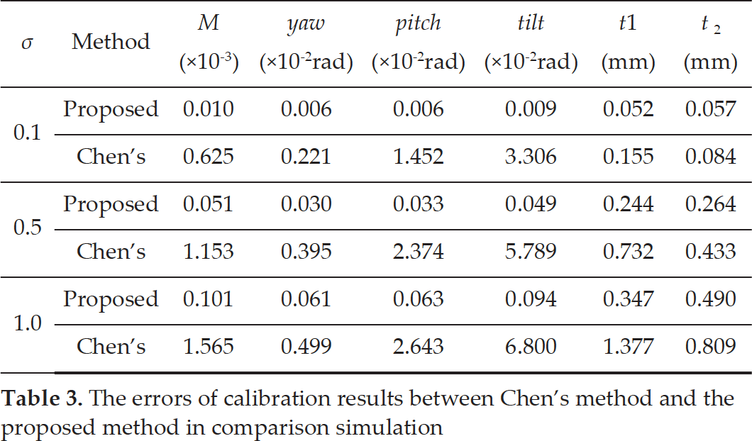
A comparison simulation is carried out between the proposed method and Chen's method [20]. The main difference between the two is the description of attitude in a non-linear refinement. The proposed method uses the independent variable of attitude description, while the four elements of truncated extrinsic attitude matrices of the camera are adopted in Chen's method. Errors in calibration results are listed in Table 3 when σ is 0.1, 0.5 and 1.0. The data demonstrate that the proposed method performs better in all calibration results.

The calibration results of computer simulation: (a) the errors of Euler angles; (b) the errors of translation vector; (c) the reprojection error
The errors of calibration results between Chen's method and the proposed method in comparison simulation
The camera and telecentric lens used in the experiment were IGV-B2520M (resolution: 2456×2058; sensor size: 2/3”; cell size: 3.45 μm) and XF-5MDT0.14X178 (magnification: 0.14; distortion: <0.05%), respectively. The calibration pattern used in the experiment is a planar pattern with an additional stage. The planar pattern is a planar board with CALTag [29], and the stage is a circle marker, as shown in Figure 4. The self-identifying pattern is able to deal with the partial visibility due to occlusion or obscuring, and the stage is used to avoid interpretations of parallel projection.
The calibration pattern is set at the range of depth of field and is observed by the camera. In the experiment, 12 pictures are taken to make the calibration, including some pictures taken at the circumstance of a high inclination angle. The planar board is handled with CALTag, while the circle marker is detected by using the ellipse fitting algorithm. The detected result of one picture is shown in Figure 5.

The calibration images (12 frames)

One of the captured calibration patterns in the real-world experiment: (a) corner detection results of the calibration pattern; (b) the additional stage detection result of calibration pattern
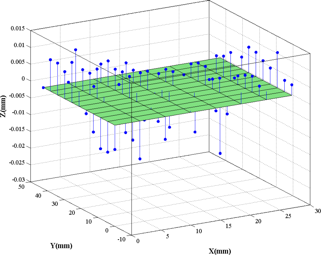
The comparison of optimized control points with ideal plane
According to the detected control points, the initial guess of the camera parameters can be achieved by the theory in Sections 3.1 and 3.2. In this calibration approach, a printed paper with control points attached to a cardboard rather than high precision calibration target is adopted, and the errors caused by the printer and the out-of-flatness of cardboard are inevitable. To avoid the mentioned errors, the coordinates of the control points are approved by camera parameters, apart from the lens distortions. The optimized results of the control points' coordinates are shown in Figure 6. In Figure 6, the points represent the control points, and the coloured plane is the ideal plane of planar board, which is the plane of Z = 0. The maximum deviation of the control points is 0.033 mm, and the absolute mean value of deviation is 0.007 mm.
After the optimization of control points and distortion-free camera parameters, the non-linear optimization of all camera parameters then follows. In the second optimization, the refined result of control points is regarded as the real value. The calibration results of the intrinsic parameters are presented in Table 4. With the calibration results, the reprojection errors (δ u , δ v ) of control points detected are shown in Figure 7, and the arithmetic means of (δ u , δ v ) are (0.073, 0.073) pixels.
The calibration results of intrinsic parameters


The distribution of reprojection errors
The truth of camera parameters cannot be found in the real-world experiments, so the reprojection errors tend to be the main judgments of the experiment's results. Besides, to verify the accuracy of the calibration results, a pair of images is chosen randomly to present the epipolar geometry relationship with the calibration results. Three control points and their corresponding epipolar lines are shown in Figure 8, and the distances between epipolar lines and the corresponding three points are 0.0069 pixels, 0.0003 pixels and 0.0029 pixels, respectively. This result just only depends on the calibration parameters, while the coordinates of control points have no impact on the result. In addition, the coordinates of the control points are measured by the intersection method, and the residuals of every point in the three directions are presented in Figure 9. The results show that the residual of the reconstruction results and the optimized real value stay at a low level for all control points. Combined with the reprojection error, it is suggested that the proposed flexible calibration method is effective and reliable.

The epipolar geometry relationship: (a) a random calibration frame and three selected control points; (b) the detected locations of control points and their associated epipolar lines on another frame

The residuals between reconstruction results and the optimized real value for every control point
To explain the performance of the proposed calibration approach, a professional calibration pattern is employed as the comparison. The accuracy of the pattern is within 1 μm, and the comparison of two types of calibration patterns is presented in Figure 10.

The objective pictures of two types of calibration pattern. Left: the cheap print product; right: the professional customized calibration pattern.
As shown in Figures 11 and 12, pictures are taken to make the calibration a comparison experiment. The data processing is the same as the proposed method except for the double non-linear optimization, because the calibration pattern is accurate enough.

The calibration images (12 frames) with professional calibration pattern
The calibration results of intrinsic parameters are presented in Table 5. With the calibration results, the reprojection errors (δ u , δ v ) of control points detected are shown in Figure 12, and the arithmetic means of (δ u , δ v ) are (0.070, 0.063) pixels.
The calibration results of intrinsic parameters with professional calibration pattern


The distribution of reprojection errors with professional calibration pattern
According to the results of the two comparison experiments, the magnification m and the reprojection errors (δ u , δ v ) are at the same level. However, there are big differences between the results of the distortion centre and distortion parameters. The main reason for this kind of status is that the distortion for a telecentric lens is quite small. A few small differences in optimization can lead to a big difference in the values of the distortion centre and distortion parameters. Actually, the influence of absolute deviation on the calibration result is not that much. Overall, the comparison experiments verify the performance of the proposed method. The proposed method is able to achieve the accuracy of the professional calibration pattern, but is much more practical and convenient.
A flexible two-step calibration method for cameras with double-sided telecentric lenses is proposed in this paper. Firstly, camera parameters with a distortion-free telecentric camera model are achieved by a closed-form solution, in which an additive stage is employed in the calibration pattern to avoid the ambiguity of orthographic projection. Then a non-linear optimization is performed to refine the coordinates of control points with distortion-free camera parameters, and follows another non-linear optimization for all the camera parameters including the distortion coefficients and distortion centre. During the designed non-linear optimization, the camera attitude is parameterized by Rodrigues's formula. Simulation and experimental results illustrate that the proposed method is effective and reliable.
According to the experimental results, it is indicated that the proposed method is able to achieve high-accuracy calibration for a telecentric lens based on a cheap print calibration pattern, which is much more practical and convenient. In addition, similar to Chen's method, the proposed method achieves the calibration of all camera parameters, including intrinsic and extrinsic ones. However, the independent variables of attitude description by Rodrigues's formula, but not the four elements of truncated extrinsic attitude matrices in Chen's method, have been adopted in the nonlinear refinement process. Further, the centre of distortion (u0, v0) has been taken into account in the calibration for high accuracy, since the centre of distortion may be significantly displaced from the centre of the image as mentioned previously.
Footnotes
Acknowledgements
The research was supported by the National Natural Science Foundation of China (No.51509251) and Open Fund of Joint Laboratory for Aircraft Measurement and Control (No.FOM2015OF012).