
Abstract
Recently, with the rapid growth of manufacture and ease of user convenience, technologies utilizing virtual reality images have been increasing. It is very important to estimate the projected direction and position of the image to show the image quality similar to the real world, and the estimation of the direction and the position is solved using the relation that transforms the spheres into the expanded equirectangular. The transformation relationship can be divided into a camera intrinsic parameter and a camera extrinsic parameter, and all the images have respective camera parameters. Also, if several images use the same camera, the camera intrinsic parameters of the images will have the same values. However, it is not the best way to set the camera intrinsic parameter to the same value for all images when matching images. To solve these problems and show images that does not have a sense of heterogeneity, it is needed to create the cost function by modeling the conversion relation and calculate the camera parameter that the residual value becomes the minimum. In this article, we compare and analyze efficient camera parameter update methods. For comparative analysis, we use Levenberg–Marquardt, a parameter optimization algorithm using corresponding points, and propose an efficient camera parameter update method based on the analysis results.
Keywords
Introduction
Up to now, the development of image processing has focused on quality ranging from high definition and full high definition to ultrahigh definition. However, it is difficult to distinguish images that are produced with higher resolutions from the human eye, so the image production method is changing to a shooting method instead of image quality. As a result, interest in virtual reality (VR) is increasing.
The 360-degree VR system is a shooting technique that allows viewing of 360 degrees by stitching images that are captured with multiple cameras. It can solve the limitations of images produced by a single camera and is widely analyzed in various fields such as computer vision and computer graphics. 1,2 However, since 360-degree VR technology is an image taken from different cameras, it is difficult to perfectly match overlapping parts. To show quality similar to the real world, estimation of the projected direction and location of an image is a very important part in image-based 360-degree VR systems. Here, the estimation of the direction and the position is solved using a relation of converting the sphere into an equirectangular with a ratio of 2:1. 3 Because 360-degree VR is shot with multiple cameras, high-quality images can be obtained by natural registration of multiple images. In addition, the 360-degree VR requires a complicated calibration process because all areas need to be connected to each other. 4
The optimization process is required to solve the complex calibration process, and the Levenberg–Marquardt (LM) algorithm is used to optimize the camera parameters. The optimization process uses the transformation relationship between images to obtain a camera parameter whose residual value is minimized. 5
The transformation of the sphere to equirectangular uses the camera parameters and their corresponding points. The camera parameter is classified into a camera intrinsic parameter composed of internal property information of the camera and a camera extrinsic parameter that contains location information. 6 The correspondence point means a pair of feature points between two images, and it is used to find the solution of the transformation relation. Camera parameters use field of view (Fov), lens distortion (K2), and rotation (yaw, pitch, and roll). Five or more equations are required to obtain five parameters, and one correspondence point can create two equations. Therefore, if there are three or more corresponding points, a camera parameter can be calculated.
The more transformations that minimize the residuals of all the corresponding points in 360 degrees, the more possible to create images that do not differ from the real world. To reduce the error of the corresponding points, the camera parameter must be well set. For this purpose, the transformation relationship is modeled to create a cost function and the optimization process is used to calculate the camera parameter that minimizes the residual value. 4
The rest of this article is organized as follows: Related works are described in the next section. In the third section, the design of the suggested method is described and the evaluation is described in the fourth section. Conclusion and future work are given in the final section.
Related work
Image stitching
Image stitching is a technique for matching multiple images to create a high-resolution image and a wide Fov image. Therefore, it combines two or more overlapping images to create a single, large, Fov image. 7
Figure 1 is the result of making a wide-view ismage of the video shot using six cameras. The process for creating a single wide Fov image is as follows.

Image stitching.
Shoot a series of images at the same location.
Calculate the transformation relationship between images.
Create a mosaic that combines the images using a transformation relationship.
The process of obtaining a transformation relationship between images consists of three steps: finding a feature point, matching a feature point, and calculating a transformation relationship using a matching feature.
Figure 2 is the matching of feature points and is used to model the relationship between two images directly in the image plane. When modeling such a two-dimensional (2-D) transformation relationship, which transformation model you use depends on the problem. It is important to choose whether to allow only rotational changes, to consider scale changes, or to consider affine or perspective changes. Although it is common to use the perspective transformation to obtain the transformation relationship of camera images, it is more likely to produce false results because of the high degree of freedom. 6,8

Matching of feature points.
Camera parameter
The world we see with our eyes is three dimensions. However, taking this with a camera, it turns into a 2-D image. In this case, where the three-dimensional (3-D) points are placed on the image, it is determined by the position and orientation of the camera at the time of taking the image geometrically. However, the actual image is greatly affected by the camera parameters such as the lens used and the distance between the lens and the image sensor. Camera calibration is the process of obtaining camera parameters. 9
The digital camera model is looking for the parameter assuming the perfect pinhole camera model, but the actual camera model may not be the pinhole camera model. Therefore, the camera parameters we have obtained may not be the same as the actual camera producing the image.
The camera image can be obtained by projecting the points on the 3-D space onto the 2-D image plane. In the digital camera model, this transformation relationship is modeled as shown in Figure 3. 6

Transformation relationship of digital camera model.
K is referred to as camera intrinsic parameter, [R|T] as camera extrinsic parameter. The combination of K and [R|T] is called camera parameter, camera matrix, or projection matrix. 6
Figure 4 refers to the camera intrinsic model. Camera intrinsic parameter is the internal parameter of camera such as focal length and principal point of camera, and camera extrinsic parameter means the geometrical relationship of camera external space such as position and direction of camera. In this study, the asymmetric coefficients are not considered in the camera intrinsic parameters and are excluded from the description.

Camera intrinsic model (pinhole camera model).
The focal length refers to the distance between the image sensor and the center of the lens. The reason why the focal length is expressed as fx and fy instead of one value is because the physical size of the image sensor may be different from each other. In general cameras, there is no difference in size between the horizontal and vertical directions, so it is not a problem to think that fx and fy are the same. 6
cx and cy are the centers of the camera lens and have a different meaning from the center of the image plane. In the case of digital image, 0 is the standard, but in the camera image plane, cx and cy are the standards. So to change from image coordinate to camera coordinate, cx and cy are added.
Figure 5 is a camera extrinsic model, which refers to a transformation relationship between camera coordinator and world coordinator. It is explained by rotation and translation transformation between two coordinates.

Camera extrinsic model.
Since the camera extrinsic parameter is not a camera-specific parameter, it depends on where the camera is installed and may also differ depending on the definition of world coordinator. To obtain the camera extrinsic parameters, the intrinsic parameters inherent to the camera must be obtained, and then the matrix that transforms it into world coordinate using the corresponding points obtained by feature matching.
Figure 6 is a perspective projection model, which uses a camera intrinsic parameter to project from 3-D to 2-D and then changes its position to world coordinate to convert the 3-D space into a 2-D image.

Perspective projection model.
Camera distortion
The digital camera model assumes a pinhole camera model. The pinhole camera model takes a lot of time to generate images because it passes a small amount of light through the pinhole. To acquire a momentary image, the image must be generated in a minimum amount of time. To solve this problem, the lens allows a lot of light to pass through in a minimum amount of time. The lens generates a minimum amount of time by passing a lot of light through the pinhole at a time, but it has a problem of causing image distortion. In general, a camera uses a lens. When a lens with a wide viewing angle is used, a wide range can be seen, but the image distortion becomes relatively worse. In addition to visual problems, such image distortion is especially problematic when accurate numerical computation is required through visual analysis. For example, if the image coordinates are converted to physical coordinates to know the actual position of the detected object in the image, a serious error will occur depending on the degree of image distortion.
Lens distortion is divided into radial distortion and tangential distortion, and various methods for distortion correction are being studied. 10 –12,13
Figure 7 is a radial distortion, which is caused by the refractive index of the convex lens. Since the image distortion is more refracted than the rays passing farther from the center, the distortion occurs in which the end becomes rounded when the square object passes through the lens.

Radial distortion.
Figure 8 is a tangential distortion, and it is caused by the problem that the lens and the image sensor are not aligned horizontally during the camera manufacturing process.

Tangential distortion.
In general, the mathematical model of lens distortion is defined in a normalized image plane from which the effects of camera intrinsic parameters are removed. If there is no distortion of the lens system, a point on the 3-D space is projected onto a point on the normalized image plane. However, it is actually distorted by the nonlinearity of the lens system. If the normalized coordinate system reflects the distortion of the lens system, then the distortion model of the lens system is shown in equation (1) 14

In equation (1), k1, k2, and k3 represent the radial distortion coefficients, and p1 and p2 are the tangential distortion coefficients. In this study, radial distortion k1, k3 and tangential distortion are considered weak, so the value is replaced with 0 (zero). r represents the distance (radius) to the principal point when there is no distortion.
Bundle adjustment
Bundle adjustment is the estimation of parameters to create an optimized structure of images by reconstructing visual images. It refers to a bundle of rays converging on each camera center passing a 3-D feature and looking for the best solution for both feature and camera positions. In addition, unlike the independent model method, which merge partial reconstruction without updating the internal structure, all structures and camera parameters are adjusted together in a bundle. 15
The independent modeling method of Figure 9 reconstructs several images and calculates them independently. It also aligns the several images in pairs and matches them to adjust the approximation. Although each model and alignment is optimal individually, the final result may not be optimal because the error values generated by the alignment do not propagate back to each model. 15 Bundle adjustment is used to solve these problems and find optimal solution and must be used essential when all images are aligned and matched at once, such as 360-degree VR systems.
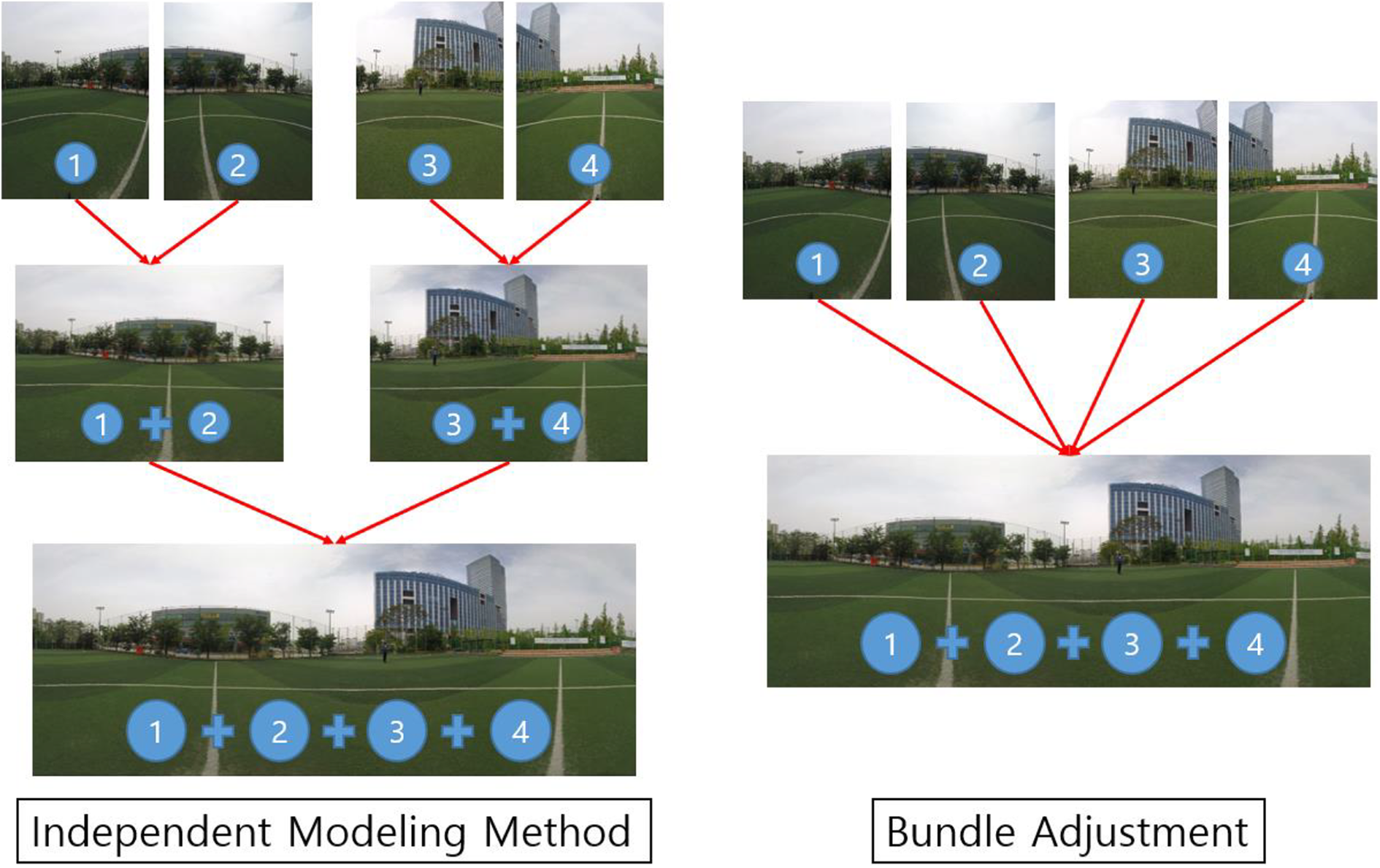
Difference between independent model and bundle adjustment. (Authors' work).
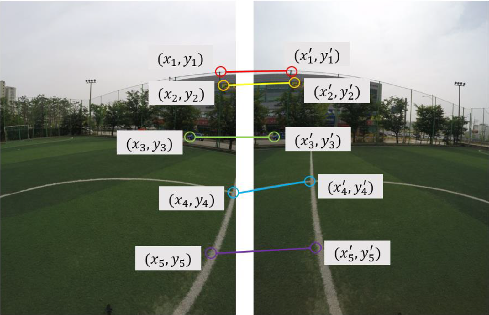
Relationship between image and correspondence points. (Authors' work; Figure 10).
Once given a geometric matching set of images, all camera parameters can be found simultaneously using the bundle adjustment. This is a necessary step when the connections between images cause cumulative errors and ignore multiple constraints between the images (the images which connect end-to-end and exceed 360 degrees). Images are added one by one by the bundle adjuster with the most matching images added at each step. The new image is initialized with the same camera position and focal distance as the best matching image. The parameter is then updated using LM. The objective function we use is a full-frame fish-eye that uses equirectangular transform functions. The error between corresponding points can be measured using the objective function. In other words, the camera parameter can be obtained by obtaining the residual sum of the corresponding points. 4
Optimization method
In this study, we use corresponding points to generate object functions. Converting model from full-frame fish-eye to equirectangular can be created using corresponding points. The LM algorithm is the optimization technique used to obtain the parameters of the generated model. The optimization technique is divided into linear least square problem and nonlinear least square problem according to the object function.
Assuming that the object function is a model considering only translations, the object function, residual function, and cost function can be expressed as equation (2).

The least square method is a method of obtaining the parameters of a model, which is to obtain the parameters of the model to minimize the sum of the residual squares with the data. If there is an object function as in equation (2), a residual function is created by using object function, and a cost function is created and evaluated to quantify the value of residual. With this formulated least square method, it is easy to obtain even more difficult object function parameters.
To find solutions using the least square method, the partial derivatives as shown below are used. By making a quadratic function by squaring the residual function and partializing the quadratic function, it can be seen that the point at which the gradient value becomes 0 is the point at which the residual value becomes the minimum value.

The result of equation (3) confirms that when calculating the parameter tx through the partial derivative, the result is the same as the method of calculating the average using the average.

Finally, the parameter calculation method of the object function using only the above translations is shown in equation (4) and the above equations can be solved by matrix operation as follows.

As a result, t can be obtained by solving
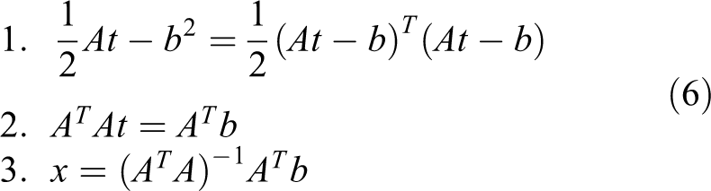
The calculation process is shown in equation (6). First, we create the cost function and partial derivative with respect to the unknown t. Finally, we create an equation for x and calculate x.
These calculation methods are called linear least square problem. However, since the object function we are actually trying to obtain is nonlinear, it belongs to the nonlinear least square problem, and the nonlinear least square problem has the difficulty of adding repetitive operations based on the linear least square problem.
In this study, LM, which is a nonlinear optimization algorithm combining Gauss–Newton method and gradient descent which are most used to optimize camera parameters, is used.
The method of nonlinear least squares iteratively improves the parameter value to reduce the sum of squared errors between the function and measured corresponding points. The LM algorithm requires an initial estimate of the parameter. Basically, these are methods of finding the local solution, so the result depends on how you give the initial value. Therefore, the better results can be obtained if giving the initial value closer to the actual solution, the better the result. In other words, if there is a way to obtain a rough estimate even if the accuracy is low, it is effective to apply the optimization techniques with the solution as the initial value after finding the solution in that way.
The method of calculating the nonlinear least square problem is based on the linear least square problem and predicts the parameter values repeatedly several times.

where
We can use our object function to create a cost function and express the sums of squares as a function F as in equation (7).
Gradient descent method is a method to move in the opposite direction of the gradient but to find a solution (a minimum point that minimizes the cost function) moving by step size proportional to the size of the gradient. J stands for the Jacobian matrix which partializes f.

The Gauss–Newton method is a solution to approximate a nonlinear function locally with a linear function. As a result, the least squares solution is obtained by linearly approximating the cost function near the current parameter estimate, and the solution is gradually approximated by finding the least-squares solution by linearly approximating the cost function near the solution. Unlike the gradient descent method, the Gauss–Newton method automatically calculates the step size, which is determined by dividing the size of the gradient by the size of the curvature. If the curvature is small (there is almost no change in the slope), the minimum value is searched for by moving more greatly. Therefore, it is more accurate and faster to find the solution than gradient descent method. However, if J_f ^ T J_f requires the inverse matrix calculation of J_f ^ T J_f and the J_f ^ T J_f is close to a singular matrix (matrix in which there is no inverse matrix), there is a problem that the calculated inverse matrix is numerically unstable and the solution can diverge.

The LM method plays the same role as the gradient descent method when the parameter is far from the optimal value and serves as the Gauss–Newton method when the parameter is close to the optimal value. 5 However, the LM method improves the Gauss–Newton method and reduces the risk of divergence by adding a constant multiplication factor μ_k of the diagonal matrix to J_f ^ T J_f. This μ_k is called a damping factor. If the value of μ_k is small, it becomes similar to the Gauss–Newton method. If the value of μ_k becomes large, it becomes similar to the gradient descent method. Damping factor is not a fixed value but a value that changes for every iteration. If the error calculated at the current step is well reduced compared to the previous error, it gives a smaller value and finds the solution using Gauss–Newton method. If not enough, give a larger value and look for the solution with the gradient descent method.

Repeated termination condition of LM method
1. Reach the number of iteration specified by the user
2. When the current function value is smaller than a user-specified threshold
3. When the change of function value is smaller than a user specified threshold.

Camera parameter update method
Parameter calculating method
Camera parameters are classified into intrinsic parameters and extrinsic parameters. In this article, intrinsic parameters are expressed as Fov, b (lens distortion K2), and principal point, and extrinsic parameters are expressed as yaw, pitch, and roll. The camera parameters that need to be optimized are Fov, K2, yaw, pitch, and roll, and the principal point is set as the center of the image. Since the number of camera parameters to be obtained is more than two, it corresponds to multivariable optimization.
In general, the 360-degree VR system should perform calibration for separate camera intrinsic parameters to support all cameras. However, the process requires a separate calibration version and additional work. In this study, to remove this process, the initial value of the camera intrinsic parameter is set by inputting the internal information of the camera in advance. In this way, setting the camera Fov value in advance, performing another camera calibration is not needed.
The process of parameter calculation is based on feature detection, feature matching, RANSAC, and optimization.
Feature detection refers to the process of finding feature points in an image, and the information of the features is data that improve parameters eventually. Feature matching is a process of finding matching pairs between feature points found in each image. Correct matching point improves the matching performance of images. RANSAC is an iterative algorithm based on hypothesis setting and hypothesis verification. In order to improve the accuracy of the matching point, we distinguished the iterative process between inlier and outlier by RANSAC. 16 Optimization uses a final inlier that is classified by RANSAC to create a transformation model and calculates optimal parameters for the generated transformation model.
The method of creating the transformation model uses transformation relation of the equirectangular in the photographed image. The transformation method is shown in Figure 11.

Full-frame fish-eye to equirectangular transformation.
First, distortion of the input image is corrected. Then, calculate the size of the output image and the Fov of each image to resize the input images. Convert resized image to spherical coordinate and apply pitch and roll. Reconvert the image converted to spherical coordinate to the equirectangular output. Finally, apply the yaw value in the equirectangular coordinate.
In this process, the matching result of output image is changed according to the parameter value for each required phase.
Figure 12 is the method of calculating distance using transformation. For accurate parameter calculation, corresponding point is used, send it to equirectangular coordinate by using parameter of image No. 1, and send it from equirectangular coordinate to full-frame fish-eye using parameter of image No. 2 again. Then, the distance between the feature point and the feature point in image 2 is calculated and the parameter with the minimum value is found. At this time, the value of distance is called residual, and the parameter is determined so as to minimize the sum or average of the squares of the values. Such a method is called the least squares method, and it can be called the nonlinear least squares method because the transformation relationship as shown in the figure has nonlinearity. The nonlinear least squares method can be solved using LM. Since the least squares method minimizes the sum of the squares of residual, it is possible to get wrong approximation results if there is at least one outlier (data apart from normal data distribution) among the corresponding points. 5 Therefore, robust parameter estimation methods, such as RANSAC, should be used if the outlier is likely to exist. 16
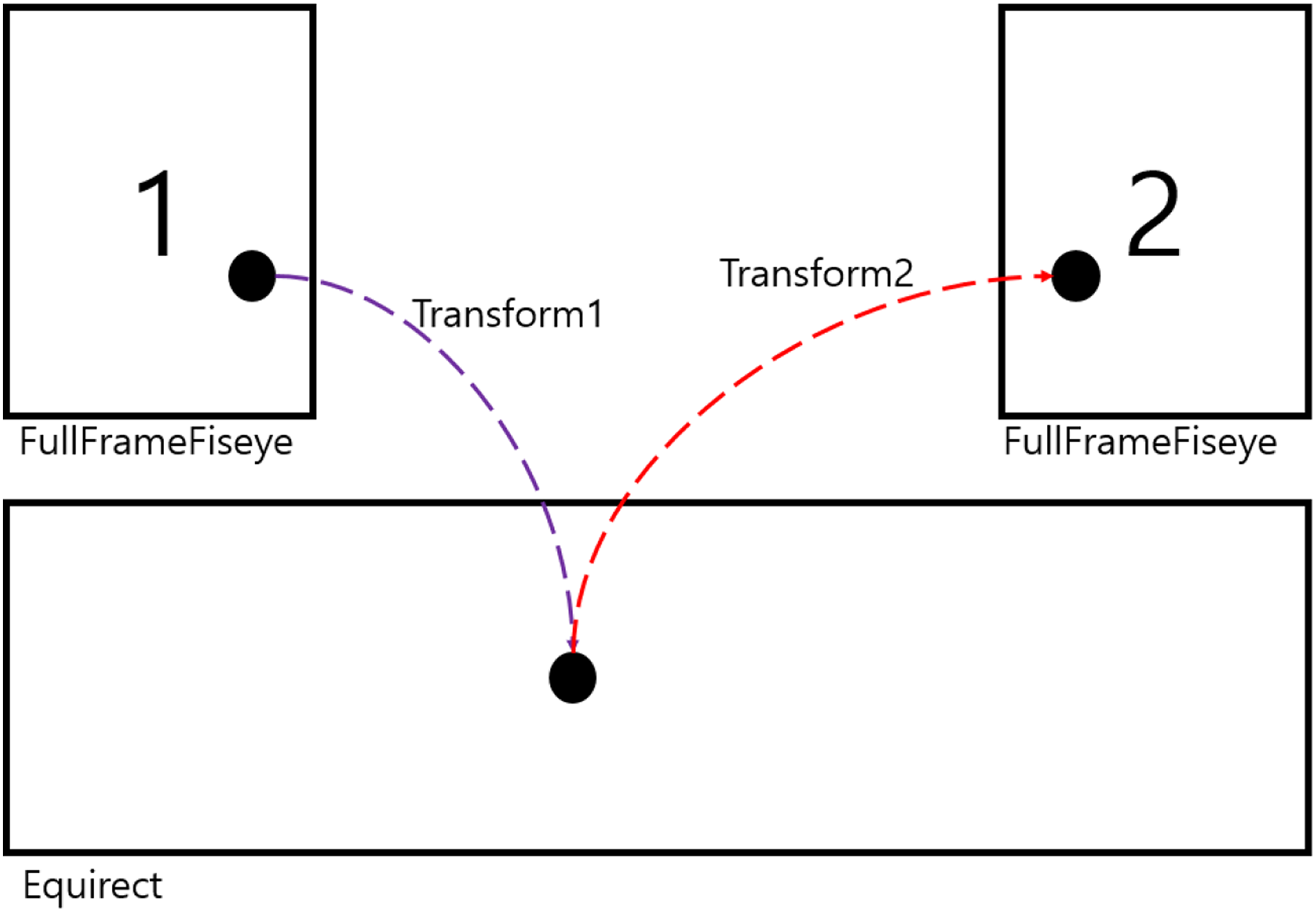
Distance calculation using transformation.
The transformation relation we define is generally called the object function, and the function that calculates the residual using the objective function is called the cost function.
Effective parameter updating method
In this article, we make a 360-degree image using six cameras. The transformation relations between six images inputted by the camera are established and six camera parameters can be obtained using the transformation relation.
Figure 13 shows the problem of 360-degrees matching, and there is some difficulty in matching the 360-degree image. Since the six images contain all 360 degrees of coverage, the ends of the image can meet again. 17 When the ends meet again, the parameters of all images are changed as well whenever the parameters of one image are changed. For this reason, many iterations are needed and the parameter update method should be well set. 4

Problem of 360-degrees matching.
One image includes Fov, lens K2, yaw, pitch, and roll, among which Fov is the most important parameter. Depending on this value, the value of the response varies greatly. Fov needs to find a stable value to find the correct values of the remaining lens K2, yaw, pitch, and roll. Since yaw, pitch, and roll represent the position information of the camera, they cannot have the same value for each image. The Fov and lens K2 values can have the same value for each image, but yaw, pitch, and roll cannot have the same values, so the updating method must be considered this difference.
Figure 14 shows the image resolution according to the change in Fov, and the Fov value represents the angle at which the image can be captured. Fov can change the size of the image, and if the Fov value increases, the size of image increases. As shown in Figure 13, the Fov is related to the resolution of the image, and if the value changes, the criterion of the residual value changes. Finally, when updating the image without fixing the Fov in the 360-degree image registration, the values of the Fov are changed with each other, and it makes difficult to find the position information (yaw, pitch, roll) of the camera due to the change in the standards of the response. This study sets initial value of Fov for accurate parameter calculation. It is assumed that the approximate Fov value of the camera is set and the value is trusted. It calculates the location information of the camera using the input Fov and recalculates all the parameters.

Image resolution according to the change in Fov. Fov: field of view.
Table 1 is a method of updating the effective parameters. Since it finds the camera position based on the value of initial Fov, reliable information of camera position can be obtained. In the case of obtaining reliable values of Fov, yaw, pitch, roll in the first place, accurate parameters can be obtained by calculating Fov, lens K2, yaw, pitch, and roll again based on the values.
Efficient parameter update method.
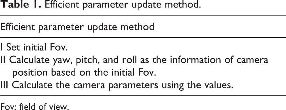
Fov: field of view.
Evaluation
In this study, we propose an efficient parameter updating method of images in 360-degree VR system. The proposed method is calculated through two optimization steps. Table 2 lists the methods for updating the parameters used in the experiment, and VBYPR means Fov, lens K2, yaw, pitch, roll, respectively.
Parameter updating method used in experiment.

Fov: field of view.
The parameter updating method calculates the 30 parameter values by inputting six images and N correspondence points (5 parameters per image). The parameters can be fixed or optimized, respectively. In case of 1 to 5, the camera parameter is calculated by one optimization process. In case of 6 to 9, the camera parameter is calculated by two optimization process. The rest of the process is the same.
The input image has a resolution of 1440 × 1080 and uses the image obtained from GoPro HERO4 BLACK. In addition, all of the tested images were directly photographed, and 20 images were used for evaluation (10 indoor images and 10 outdoor images). The comparison criteria are divided into two major categories, residual value of the cost function and the number of calls of the cost function. The residual value of the cost function is a distance value between the corresponding points calculated through the transformation model. The smaller the residual value, the closer to the real world, and the lower the number of calls to the cost function, the faster the processing speed.
Figure 15 shows the error rate of the parameter update method. It can be confirmed that the residual value calculated through the two optimization processes is lower than the residual value calculated through one optimization process. However, when Fov and lens K2 are optimized together with YPR, the solution may not converge or go out by the wrong direction. The above experimental results show that if the criteria of Fov and lens K2 values are not precisely captured, the wrong camera parameters can be obtained in the optimization process.
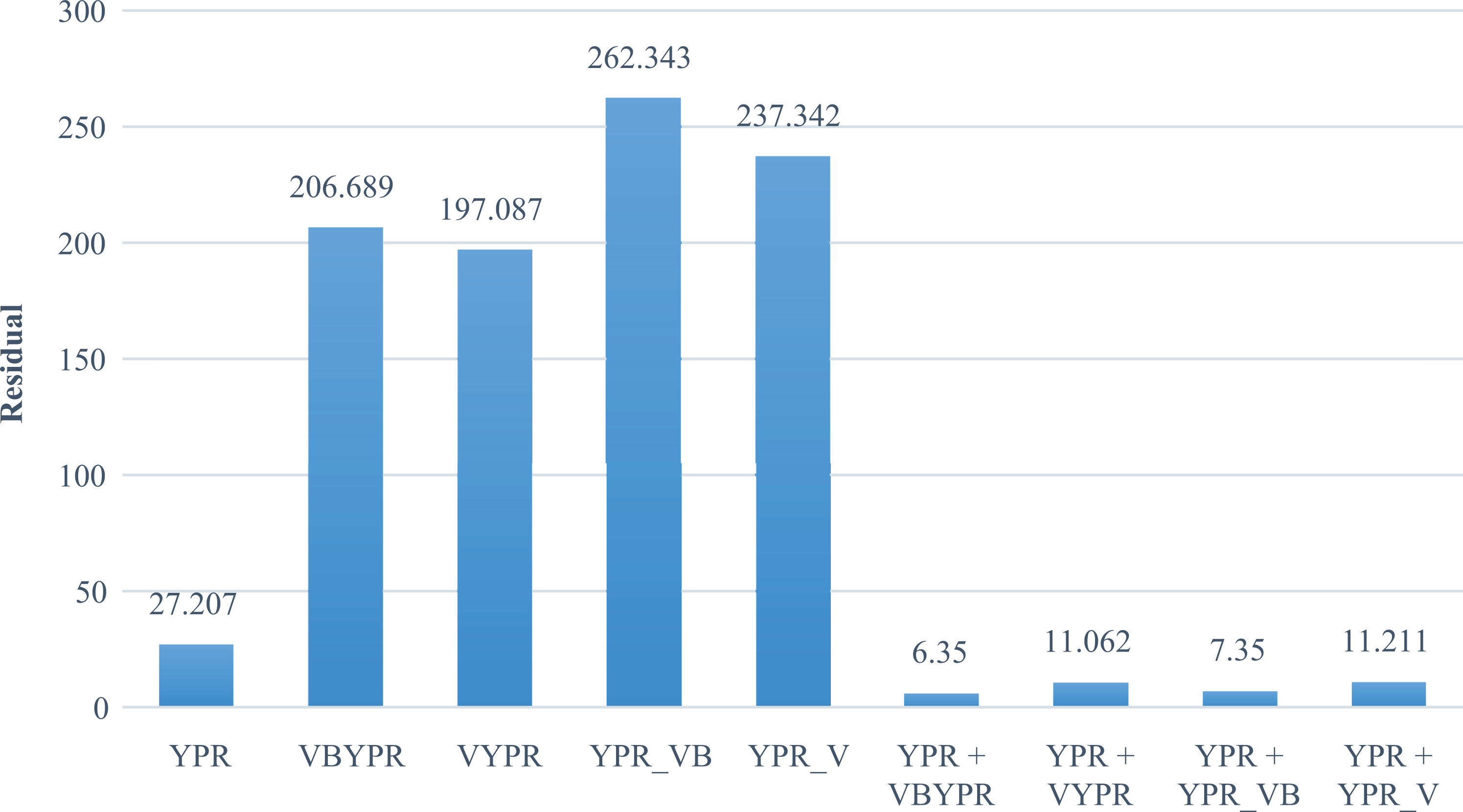
Error rate of parameter update method.
Table 3 shows how the values of Fov and lens K2 change after the optimization process. Because we tested with six cameras, we show six Fov and lens K2 values, respectively. The type in which six cameras use the same Fov and lens K2 each represents one value. In the case of YPR, since Fov and lens K2 are used as initial values, there is no change in the values, but the Fov and lens K2 values of VBYPR, VYPR, YPR_VB, and YPR_V are updated to values far out of the initial value through optimization. The above data are evidence that the values of Fov and lens K2 have changed to wrong values, which means that optimization did not find the optimal value. In conclusion, if the information is not searched based on the initial value presented in the article, the value of Fov or lens K2 will change in the wrong direction. The reason is that if you change the value of lens K2 according to the change of Fov, there is a way to reduce the error, and you can find a way to reduce the error even if you only change Fov according to the change of lens K2. We have confirmed through experimentation that we can greatly affect the matching performance by how to set the values of Fov and lens K2.
Comparison of changes of Fov and lens K2.

Fov: field of view.
The method of calling the proposed optimization procedure twice in this article is performed by setting the values of Fov and Lens K2 differently as shown below.
First, optimization uses Fov and lens K2 to set the initial value proposed in the article and update the YPR.
Second, optimization uses the four proposed methods (VBYPR, VYPR, YPR_VB, YPR_V).
The results of the four tests show that the best performance is achieved when calling VBYPR after YPR call, and the second best performance when calling YPR_VB after YPR call.
In summary, we set Fov and lens K2 as the proposed initial value and call the YPR optimization to calculate the camera position information corresponding to the initial value. When the initial values of approximate camera parameters are set, it is most effective to calculate the camera parameters (Fov, lens K2, yaw, pitch, roll) by calling VBYPR optimization or YPR_VB optimization.
Figure 16 shows the result of measuring the execution speed of the optimization. The execution speed was measured by the number of calls of the cost function. The number of calls was measured only by the method of calling the optimization process twice. Among the proposed methods, VBYPR, VYPR, YPR_V, and YPR_VB excluding YPR have no meaning to measure the number of calls of the cost function because the values do not converge or the value exceeds the allowable value. The method of calculating stable camera parameters is a method of repeatedly calling the optimization process twice. As a result of measuring the number of calls of the cost function of these methods, it showed the fastest processing speed when calling YPR_VB after calling YPR. The slowest method among the proposed methods is to call VBYPR after YPR call. However, this method has the lowest residual value. In conclusion, if accuracy is more important than speed, it is best to call VBYPR after YPR call, and it is most efficient to call YPR_VB after YPR call if priority is given to speed.

Number of cost function iterations of parameter update method.
Table 4 shows comparison of success rates with other solutions. It is confirmed that the proposed algorithm has a stable matching success rate with two optimization processes. However, the high success rate does not mean that the matching performance is high, and the matching success rate is insufficient to be evaluated only by the optimization method. Feature detection, feature matching, and many other factors can affect the results.
Comparison of success rates with other solutions.
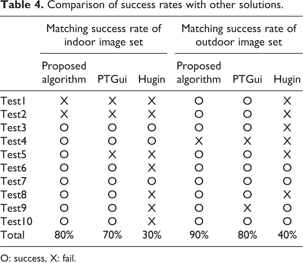
O: success, X: fail.
Since the transformation model used for 360-image matching can vary depending on the implementation method, absolute comparison with other solutions is difficult. Therefore, the purpose of this article is to provide a more stable method for updating the parameters of the current solution.
Conclusion
In this article, we have experimented various camera parameter updating methods and proposed an optimal method to improve the matching performance of 360-degree images. Even though there are initial Fov and initial lens K2 values, there is a problem that the values of Fov and lens K2 greatly change in the optimization process when the corresponding points are densified or linear. Also, if the position of the camera is not set based on the set Fov value, there is a problem that the camera parameter converges or diverges to the wrong value in the optimization process. To solve these problems and to obtain stable and accurate values of Fov and lens K2, we performed a second optimization to update the entire camera parameters after pre-optimization and obtained more accurate camera parameter values. Camera parameter update method calculates yaw, pitch, roll with initial Fov, lens K2 value and recalculates all camera parameters using calculated Fov, lens K2, yaw, pitch, roll values. By using the value of initial Fov to find the camera position information, it is possible to find the optimal camera parameter value with a small number of repetitions. In addition, since the optimization starts from the camera parameter value that is close to the correct answer, the subsequent process also proceeds with a small number of iterations. Assuming that all methods are going to the optimal solution, it is more likely that the number of iterations of the cost function that calls the optimization process twice is less than or equal to the number of iterations of the cost function that once called the optimization process. In conclusion, we confirmed the optimization method that can achieve high matching performance and fast execution speed through several experiments.
In the future, we will investigate other efficient method to calculate the solution of the Fov value stably. According to the experimental results of the article, it was confirmed that if the value of Fov is found without the location information of the camera, it goes in the wrong direction. In this way, if the Fov or lens K2 value going in the wrong direction can go in the right direction, it will be possible to obtain high matching performance with calling the one optimization process without calling the optimization process twice. Therefore, research on the Fov stabilization algorithm should be carried out to find the more objective and accurate direction. Also, a camera with a wide Fov value is difficult to match the images due to severe distortion of the lens, and it is difficult to find the Fov value for matching. Therefore, it is necessary to add a method to improve the matching performance for the wide Fov value.
Footnotes
Authors’ note
The data used to support the findings of this study are available from the corresponding author upon request.
Declaration of conflicting interests
The author(s) declared no potential conflicts of interest with respect to the research, authorship, and/or publication of this article.
Funding
The author(s) received no financial support for the research, authorship, and/or publication of this article.