
Abstract
Targeted therapy using magnetic microparticles and nanoparticles has the potential to mitigate the negative side-effects associated with conventional medical treatment. Major technological challenges still need to be addressed in order to translate these particles into in vivo applications. For example, magnetic particles need to be navigated controllably in vessels against flowing streams of body fluid. This paper describes the motion control of paramagnetic microparticles in the flowing streams of fluidic channels with time-varying flow rates (maximum flow is 35 ml.hr−1). This control is designed using a magnetic-based proportional-derivative (PD) control system to compensate for the time-varying flow inside the channels (with width and depth of 2 mm and 1.5 mm, respectively). First, we achieve point-to-point motion control against and along flow rates of 4 ml.hr−1, 6 ml.hr−1, 17 ml.hr−1, and 35 ml.hr−1. The average speeds of single microparticle (with average diameter of 100 μm) against flow rates of 6 ml.hr−1 and 30 ml.hr−1 are calculated to be 45 μm.s−1 and 15 μm.s−1, respectively. Second, we implement PD control with disturbance estimation and compensation. This control decreases the steady-state error by 50%, 70%, 73%, and 78% at flow rates of 4 ml.hr−1, 6 ml.hr−1, 17 ml.hr−1, and 35 ml.hr−1, respectively. Finally, we consider the problem of finding the optimal path (minimal kinetic energy) between two points using calculus of variation, against the mentioned flow rates. Not only do we find that an optimal path between two collinear points with the direction of maximum flow (middle of the fluidic channel) decreases the rise time of the microparticles, but we also decrease the input current that is supplied to the electromagnetic coils by minimizing the kinetic energy of the microparticles, compared to a PD control with disturbance compensation.
1. Introduction
Recently, magnetic micro and nanoparticles have attracted much interest in nanomedicine and nanotechnology [1, 2]. Their miniature size allows them to access deep-seated regions within the human body and execute targeted therapy and diverse biomedical applications [3–9]. Many researchers have proposed the utilization of biodegradable magnetic nanocapsules, nanoparticles, and microparticles (magnetic drug carriers) in drug delivery applications [10–14]. These carriers can be injected into the human body through the circulatory system, and external magnetic fields are applied to concentrate these carriers at a specific diseased cell. The miniature size of these carriers makes their motion control and positioning a challenge in the presence of flowing streams of a fluid; these problems are most likely to occur in biomedical applications and targeted therapy.
A few research groups have proposed a variety of self-driven [15–17] and magnetically-driven [18] mechanisms to overcome the flowing streams inside fluidic channels. Open-loop control of self-propelled microjets has been achieved inside fluidic channels against the flowing streams of hydrogen peroxide solution [15]. The control accuracy of these microjets has been improved using closed-loop control with microscopic image guidance. This control has enabled propulsion of the microjets along and against the flowing streams of the hydrogen peroxide solution [19]. Although these microjets can overcome the flowing streams of the solution and achieve non-trivial tasks, their locomotion mechanism does not allow them to be used in biomedical applications, because of the toxicity. No research has yet addressed the optimal path that allows the microjet to reach a reference position in minimal time or with minimal control effort. Positioning of ferromagnetic nanoparticles inside rats was achieved by Nacev et al. [20] by directing external magnetic fields towards a desired position without feedback. Belharet et al. presented a method for predictive control of magnetic microrobots in a in microfluidic arterial bifurcations using fluids with different viscosities [18]. Minimal input control of paramagnetic microparticles in three-dimensional (3D) space has been achieved using an electromagnetic system with closed configuration [21]. This optimal control might increase the availability of electromagnetic coils during the positioning of the microparticles in 3D space, as the input current to the electromagnetic coils is decreased. However, magnetic control has been achieved in a stationary fluid without flow. In this study, we achieve the following:
Modelling of the motion of paramagnetic microparticles in flowing streams inside fluidic channels;
Development of a robust closed-loop motion control system that allows for the positioning of the microparticles within the vicinity of a reference position in the presence of time-varying flow;
Finding the optimal path that enables controlled motion against the flow towards the reference position with minimal kinetic energy.

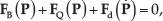
A controlled paramagnetic microparticle moving along an optimal trajectory against time-varying flow inside a fluidic channel. Maximum and minimum flows (
We analyse the motion of the microparticles in a low-Reynolds-number regime, and develop a model for their motion in a fluid with a time-varying flow rate (Fig. 1). This model is used in the design of a robust motion control system based on disturbance force estimation and compensation [22]. In addition, we find the path that allows the microparticles to move towards a reference position with minimal energy to decrease the kinetic energy of the controlled microparticles.
The remainder of this paper is organized as follows: Section 2 provides modelling of the motion of microparticles inside fluidic channels [23] and a comparison between the model and the experimental results. The designs of robust and optimal motion control systems are included in Section 3 using a disturbance observer technique and the calculus of variation theory, respectively. Section 3 also provides motion-control experimental results using a magnetic system with orthogonal electromagnetic configuration and under microscopic guidance. Discussions pertaining to the magnetic-based motion control of microparticles and the challenges that have to be overcome to translate them into biomedical applications are provided in Section 4. Finally, Section 5 concludes and provides directions for future work.
2. Modelling and Characterization of Microparticles Inside Channels
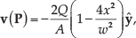
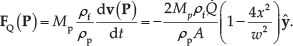
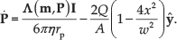
The motion of a magnetic microparticle under the influence of a magnetic field
where

where
where x is the x -component of the position vector

An electromagnetic system ① for the motion control of paramagnetic microparticles inside a fluidic channel ②. The inlet and outlet of the channel are connected to a dual pump (FIAlab-3200 Dual Pump Sequential Injection Analyzer, FIAlab Instruments Inc., Bellevue, USA). ③ to generate controlled time-varying flow rates. The inset shows that the magnetic field gradient holds a microparticle against a flow rate of 35 ml.hr−1. The reference position is indicated using the small blue circle. The red square indicates the position of the drug carrier and is assigned using our feature tracking algorithm. The red arrows indicate the direction of the flow. Please refer to the accompanying video that demonstrates a representative motion control of a paramagnetic microparticle against the flow of oil.
In (4),

where η is the dynamic viscosity of the fluid and

We study the motion control of paramagnetic microparticles inside a fluidic channel for the following cases: motion control in a stationary fluid, control against a unidirectional flow along a single axis, and motion control in the
2.1. Motion of microparticles in a stationary fluid
In a stationary fluid, as shown in Fig. 3,


A representative closed-loop motion control of a paramagnetic microparticle in the absence of flow. The red square and the small blue circle indicate the position of the microparticle and the reference position, respectively, and are assigned using our feature tracking algorithm [35]. Please refer to the accompanying video that demonstrates the motion control of microparticles in a fluidic channel with zero flow.
The motion of the microparticle is controlled by the magnetic field gradient. Fig. 3 shows the motion of a microparticle under the influence of the magnetic field gradient in a stationary fluid. In this representative experiment, the microparticle is pulled at an average speed of 80 μm.s−1 towards the reference position (small blue circle). Using (6), the magnetic force-current map entry (
2.2. Motion of microparticles in a fluid with constant unidirectional flow along a single axis
A constant unidirectional flow rate

The velocity
2.3. Motion of microparticles in a step-wise changing unidirectional flow along the xy plane
In this case, the flow is changed step-wise with N steps at times tn as follows:
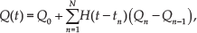
where

Therefore, the velocity
The model of the microparticle is used in the design of a closed-loop motion control system inside a fluidic channel with time-varying flow rates.
3. Motion Control Inside Fluidic Channel with Time-varying Flow Rates
Motion control of microparticles inside a fluidic channel is achieved using a PD control system, PD control with disturbance compensation, and an optimal control system.
3.1. Design of proportional-derivative control system
The magnetic field gradients are controlled using (2) to pull the microparticle towards a reference position and achieve positioning within the vicinity of the reference position against different flow rates. For this, we devise a PD control system. Therefore, (1) can be rewritten as follows:

where

where
where


Characterization of the average speed of the paramagnetic microparticle against five representative flow rates. This experiment is repeated using three current inputs. Input current of 2.4 A (black line) provides magnetic field gradient of 56 mT.mm−1 and magnetic field of 33 mT. Input current of 3.5 A (red line) provides magnetic field gradient of 122 mT.mm−1 and magnetic field of 48 mT. Input current of 4.7 A (blue line) provides magnetic field gradient of 221 mT.mm−1 and magnetic field of 65 mT. The average speed is calculated using five open-loop trials along the y-axis using microparticles with average diameter of 100 μm.
Fig. 3 shows a representative closed-loop motion control of a microparticle in a stationary fluid. The microparticle is pulled towards the reference position using the PD control input (first two terms in (12)). In this experiment, we observe that the microparticle is controlled at an average speed of 150 μm.s−1 and the steady-state error is 3 μm. The error dynamics (12) indicate that the gain matrices must be positive-definite to achieve stable position control of the microparticle. In a stationary fluid (
We apply flow rates of 4 ml.hr−1, 6 ml.hr−1, 17 ml.hr−1, and 35 ml.hr−1, and control the motion of the microparticle at each flow rate using similar control gains (12), as shown in Fig. 5. At flow rate of 4 ml.hr−1, the speed of the microparticle against the flowing stream of the fluid is measured to be 150 μm.s−1, whereas the steady-state error is calculated to be 10 μm. At flow rate of 35 ml.hr−1, the average speed of the microparticle against the flow is decreased to 125 μm.s−1 and the steady-state error is increased to 64 μm. Please refer to the accompanying video that demonstrates the closed-loop motion control of a microparticle against the four flow rates using the PD control system. The transient- and steady-state characteristics of the PD control system are affected by the varying flow rate. Therefore, this effect can be compensated using disturbance estimation and compensation.

A representative motion control result of a microparticle against flow rates of 4 ml.hr−1, 6 ml.hr−1, 17 ml.hr−1, and 35 ml.hr−1 using control law (12). The control gains
3.2. Design of proportional-derivative control system with disturbance estimation and compensation
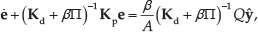
The drag force and the force due to time-varying flow rate exerted on the microparticle can be estimated using its velocity and the current inputs to the electromagnetic coils [22, 29, 30, 31, 32]. The estimated disturbance force
where g is the gain of the low-pass filter, and

The first three terms in (17) represent the PD control input with disturbance compensation. The estimated disturbance force is a positive-feedback loop that allows for the compensation of the disturbance drag force in the channel, whereas the second and third terms provide the outer loop that stabilizes the motion of the microparticle [22].
Fig. 6 provides a representative motion control result of a microparticle against flow rates of 4 ml.hr−1, 6 ml.hr−1, 17 ml.hr−1, and 35 ml.hr−1. Control law (17) is implemented with similar control gains for the mentioned flow rates. The control gains

A representative motion control result of a microparticle against flow rates of 4 ml.hr−1, 6 ml.hr−1, 17 ml.hr−1, and 35 ml.hr−1 using control law (17). The control gains
The PD control system with disturbance compensation allows the microparticle to overcome time-varying flow rates, as shown in Fig. 7. In this experiment, the flow rate is increased from 6 ml.hr−1 to 17 ml.hr−1 at time t =28 seconds. At time t =68 seconds, the flow rate is increased from 17 ml.hr−1 to 35 ml.hr−1. The disturbance caused by the time-varying flow is compensated by the additional control input (
3.3. Design of optimal control system
An optimal path has to be determined to pull the microparticle against the flowing streams of a fluid while minimizing a cost function, such as the time to reach a reference position, the input current vector, or the total energy [21]. We assume that the microparticle moves from the point

Therefore, the Hamiltonian function

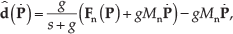
where λ is a vector of the co-states. The necessary condition on the optimal path is given by [33]

where

where


A representative closed-loop motion control of a paramagnetic microparticle against fluid with time-varying flow rate. The flow rate is increased at time t =28 seconds and t = 68 seconds to 17 ml.hr−1 and 35 ml.hr−1, respectively. The green line indicates norm-2 of the current vector to show the effect of the compensating control input. This input mitigates the effect of the time-varying flow and allows the microparticle to be localized within the vicinity of the fixed reference position (indicated by the red line). The control gains
Equations (20), (21), and (22) are solved simultaneously for the optimal path (

where w is the width of the fluidic channel and
Our control system assigns waypoints along the optimal path (small orange points), and the microparticle is pulled towards each of the waypoints, as shown in Fig. 8. In this representative experiment, the microparticle is controlled at an average speed of 386 μm.s−1 and is localized at the reference position with maximum error of 5 μm. The initial position of the microparticle and the reference position (small blue circle) are adjusted to be aligned along the centre-line of the fluidic channel. This adjustment subjects the microparticle to maximum flow (
Table 1 provides a comparison between the PD control system, PD control with disturbance compensation, and optimal control system in the transient (rise time and average speed) and steady state (maximum position error). The rise time (time taken by the microparticle to reach the reference position) of the optimal control system is greater than that of the PD control system and the PD control system with disturbance compensation. The optimal control system pulls the microparticle along the optimal path, as shown in Fig. 8. Therefore, the microparticle does not move along the shortest path and the rise time is increased compared to the PD control system. Nevertheless, we observe from the comparison in Table 1 that the microparticle reaches maximum speed under the influence of the optimal control system for all flow rates. We attribute this increase in the average speed to the optimal path taken by the controlled microparticle. This optimal path is quadratic (based on (23)) and allows the microparticle to avoid maximum forces due to drag and time-varying flow. The microparticle moves towards the walls of the fluidic channel where the flow is lower than that at the middle of the channel based on (3). The PD control system does not provide an optimal trajectory for the microparticle, but it does provide a magnetic force pulling towards the reference position regardless of the direction of flow, initial position of the microparticle, and reference position. Therefore, the microparticle is subjected to maximum force due to the time-varying flow in the channel.

A representative motion control along an optimal path (black curve) between the initial (at t=8.0 seconds) and reference position (small blue circle) of the microparticle. The orange points indicate waypoints that are assigned by our closed-loop control system along the optimal path. The optimal path is calculated using (23) and the microparticle is pulled towards the waypoints using the optimal input (22). The flow rate in this experiment is 35 ml.hr−1. The horizontal dark line indicates the edge of the fluidic channel. The dashed black arrows indicate the walls of the channel. Please refer to the accompanying video that demonstrates our motion control along an optimal path.
4. Discussions
The magnetic-based control systems presented in this study are fairly general, even though the experimental work is done using paramagnetic microparticles of spherical geometry. These control systems can be implemented on microrobots such as artificial helical flagella [38, 39], magnetotactic bacteria, superparamagnetic particles, ferromagnetic particles, and microparticles with irregular shapes. The range of flow rates used in this study is similar to that used in animal experimentation. Mouse carotid flow rates average approximately between 14.4 ml.hr−1 and 42 ml.hr−1 [20]. Therefore, the electromagnetic configuration and the magnetic-based control system hold promise for medical application. They allow us to navigate microparticles controllably against flow rates that are similar to those used in animal experimentation. Therefore, they can be used to implement targeted drug delivery using mice or test chemotherapeutic agents coated on the microparticles in vivo. However, the following challenges still need to be addressed in order to translate the targeted drug delivery using magnetic microparticles into in vivo experimentation:

Optimal motion control of paramagnetic microparticles along an optimal trajectory between the initial position of the microparticle and the reference position. The flow is applied along the y-axis and the initial and reference positions are collinear with the maximum flow within the channel. The controlled microparticle follows a quadratic path (23) towards the reference position (vertical red line) against flow rates of 4 ml.hr−1, 6 ml.hr−1, 17 ml.hr−1, and 35 ml.hr−1. The black and red arrows indicate the direction of the microparticle and flow, respectively. (a, b, c, and d) Motion of the microparticle against flow rates of 4 ml.hr−1, 6 ml.hr−1, 17 ml.hr−1, and 35 ml.hr−1, respectively. Please refer to the accompanying video that demonstrates our motion control along an optimal path.
The flow rates of blood in the aorta, arteries, capillaries, veins, and vena cava are higher than the flow rates used in this study and necessitate larger magnetic field gradient to move and hold the microparticles;
Clinical imaging modality must be integrated into the electromagnetic configuration to provide feedback to the control system, and its resolution has to be at the micro scale;
The biocompatibility and physiological conditions of the drug release must be studied and implemented experimentally.
The closed configuration of electromagnetic coils cannot be scaled up to the scale of in vivo devices. Therefore, the first challenge can be overcome using an electromagnetic system with open configuration [40, 41]. The second challenge can also be overcome using an electromagnetic system with open configuration, since it will provide larger space to incorporate an imaging modality, e.g., an ultrasound system [36]. The ultrasound probe can be moved using a robotic arm in relation to a permanent magnet that is fixed to the end-effector of another robotic arm. This configuration will enable motion control and positioning of magnetic drug carriers throughout relatively large workspaces and with higher field gradient than that provided by electromagnetic systems with closed configurations. The biocompatibility of the used microparticles and the amounts of drug required for the therapy should be optimized; the drug release per unit time should also be taken into consideration based on the binding and rebinding between the targeted drug and the microparticles they are immobilized on. This should be optimized first in vitro under similar experimental conditions to the physiological ones in terms of the amount of drug to be immobilized, pH, matrix, and flow rate.
Closed-loop control characteristics of the proportional-derivative (PD) control system, PD control system with disturbance compensation, and optimal control system. The average rise time, average speed, and maximum error are calculated from 15 motion control trials at each flow rate. Control laws (12) and (17) are used to implement the PD control with and without disturbance compensation, respectively. The optimal path and optimal control input are calculated using (23) and (22), respectively.

5. Conclusions and Future Work
This paper has reported an experimental demonstration of motion control of paramagnetic microparticles against flowing streams of a fluid using a PD control system with and without disturbance compensation. The PD control allows a controlled microparticle to move against flow of 35 ml.hr−1 at average speed of 125 μm.s−1, whereas the disturbance compensation achieves average speed of 375 μm.s−1. In the steady state, the PD control systems with and without disturbance compensation achieve positioning with maximum positioning error of 64 μm and 18 μm, respectively, against flow of 35 ml.hr−1. The robustness of the PD control with disturbance compensation is tested experimentally by applying time-varying flow rate of 14 ml.hr−1 to 35 ml.hr−1. The additional disturbance control input compensates for the increased drag force and force due to time-varying flow rate, and achieves maximum position tracking error of 18 μm at flow rate of 25 ml.hr−1. The optimal path between two points inside a fluidic channel has also been studied, using calculus of variation. We find that following a quadratic trajectory from the initial position to the final destination against the flow not only increases the speed of the microparticles (for all flow rates), but also achieves acceptable maximum position error compared to the PD control system with disturbance compensation.
In future studies, the motion control presented in this paper will be implemented in simulated body fluid, and our electromagnetic system will be adapted to incorporate a clinical imaging modality [36, 37]. In addition, the electromagnetic coils will be modified to generate magnetic field gradient larger than 220 mT.m−1 to enable the control of microparticles against flow rates greater then 35 ml.hr−1. We will also develop fluidic channels with multiple inlets to induce flow from arbitrary directions. This modification will enable us to study the robustness of the motion control system against arbitrary disturbance forces. The microparticles will be coated with chemotherapeutic agents and the physiological conditions of the drug release will be studied in the presence of time-varying flow.
Footnotes
6. Acknowledgements
The authors acknowledge the funding provided by the German University in Cairo and the DAAD-BMBF funding project. The authors also acknowledge the funding from the American University in Cairo (Faculty Support Research Grant).
The authors would like to thank Ms Heba Hassan for her assistance with the design of the optimal motion control system and for her valuable feedback during the preparation of this work.