
Abstract
Parallel robotic mechanisms are generally used in flight simulators with a motion-cueing algorithm to create an unlimited motion feeling of a simulated medium in a bounded workspace of the simulator. A major problem in flight simulators is that the simulation has an unbounded space and the manipulator has a limited one. Using a washout filter in the motion-cueing algorithm overcomes this. In this study, a low-cost six degrees of freedom (DoF) desktop parallel manipulator is used to test a classical motion-cueing algorithm; the algorithm's functionality is confirmed with a Simulink real-time environment. Translational accelerations and angular velocities of the simulated medium obtained from FlightGear flight simulation software are processed through a generated washout filter algorithm and the simulated medium's motion information is transmitted to the desktop parallel robotic mechanism as a set point for each leg. The major issues of this paper are designing a desktop simulation system, controlling the parallel manipulator, communicating between the flight simulation and the platform, designing a motion-cueing algorithm and determining the parameters of the washout filters.
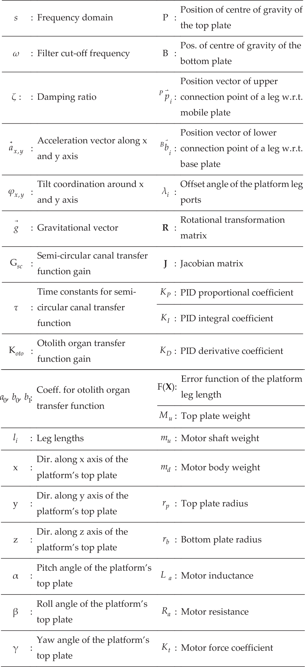
List of Symbols
Introduction
Flight simulators are necessary for studies related to vehicle design and tests, and simulator systems help us understand pilot behaviour that is close to reality. Flight simulators provide an economical and secure way of testing new technologies for implementing in aircraft. Several universities and industrial laboratories are undertaking research for new generation prototypes and vehicle dynamic models.
Simulators create a realistic flight feeling using motion information feedback [1], and are completely reliable, realizable and easy to implement. It is proposed to increase this reality by improving the software, hardware and physical abilities of simulators. To get closer to the real flight feeling, it is important to employ a robust motion-cueing algorithm [2].
Simulators are generally human in the loop(HITL) processes and include an intensive code algorithm. For instance, in a Level-D simulator there are numerous code arrays, which are expensive software systems. Because of their complex structure and high cost, simulator design is quite a difficult task [3].
In simulator systems, examining which factors cause the differences between real and virtual data is needed. These factors are generally separated into three categories:
human motion perception (vestibular) systems
the problems that may occur in visual flight simulation
audio feedback
The questions possible in applications targeting human motion perception are:
What does human perception depend on in real-time applications?
How is it possible to improve human perception by changing the parameters of a flight simulation system? [4]
Human motion perception systems are the basis of motion perception studies. Humans sense motion through the vestibular system located in the inner ear, which consists of semi-circular channels sensing angular motion and otoliths sensing translational motion. Mathematical models of the vestibular system were first represented in [5] and simplified transfer function models were presented in [6]. Then simulation studies became possible.
The otoliths are the human sensory system for translational accelerations and are stimulated by head position. There are three semi-circular canals for sensing angular acceleration or rotational motion. Corresponding signals are sent to the neural system through nerve fibres by the otolith organs' receptor cells and semi-circular canals. The utricle and saccule are the otolith organs in the ear. The utricle senses horizontal motion and the saccule senses vertical motion. The vestibular system is associated with other organs responsible for sensing motion and it plays a major role in the balance of a human body [7, 8].
The otolith organs sense acceleration and the effect of gravity on the tilt of the pilot's head. Since the otoliths, acceleration and tilt are associated with one another, this term is called tilt coordination and it improves the accuracy of any simulation. The tilt effect is performed by passing the aircraft translational acceleration through a low-pass filter. Additional low-pass filters are added into the motion-cueing algorithm in the pitch/surge and roll/sway modes [9] to integrate the tilt coordination into the motion-cueing algorithm.
Visual scaling results in differences in image perception. The optimal level of visual scaling affects the image perception positively. Changes in visual feedback were studied under different visual scale factors in [10].
Additionally, image depth and slope play a significant role in motion perception. Studies performed by Jamson confirmed that to create an accurate motion perception, the horizontal size of the image needs to cover 120°. In [10], the pilot was asked to move at a certain speed and simulation accuracy was tested.
Naturally, visual feedback in a simulation plays a significant role in motion perception. Image workflow, resolution or deflections in frequency adjustment create problems.
Initially, it was discovered that the image a pilot senses is based on differences in the optical workflow, which is a dynamic model the brain uses to solve a specific motion and helps the pilot predict absolute velocity, distance and relative spatial range. This image signal is effective for understanding major tasks like velocity of the vehicle, distance from objects and lateral control [4].
Audio feedback is less effective in motion perception. Sound is based on simulation acoustics and the number of sounds supplied. Sound-emitting objects in the virtual environment make it easier to get an accurate space. Research has showed that sound is not effective in velocity control and it has been proved that rotation, lateral and yaw motion play a major role in sound vibration [4].
Inertial cues are very important for simulators. Without them, the pilot has no information about aircraft acceleration or rotation. Unlike real vehicles, motion platforms have limited workspace for rotation and acceleration. Motion-cueing algorithms are called washout filters and can be classified into several categories. These filters produce motion commands to be sent to the motion platform [11].
There are four algorithms in the literature for motion cueing:
classical approach
optimal algorithm
adaptive base algorithm
model-predictive approach
The classical algorithm was founded in the NASA Ames Research Center by Conrad and Schmidt in 1969 and Conrad, Schmidt and Douviller created the rotating coordinate filter in 1973. Generally, the classical approach consists of a combination of high- and low-pass filters in which the cut-off frequency and damping ratio are initially set. While examining the acceleration effect, integrating the gravitational effect into the acceleration change in the vertical direction is also an important issue. First, translational accelerations and angular velocities are scaled and angular velocities are passed through high pass filters. To return the simulator to its initial position, second- and third-order filters are used. If the effects are scaled and limited, then just the second-order filter is sufficient [12].
Because of the workspace limitations of a simulator, an adaptive algorithm was developed by Parrish, Dieudonne, Bowles and Martin in 1975, which is implemented in the frequency domain to eliminate the limited workspace problem. In this algorithm the coefficients are different [13] and motion perception is considered a tracking problem [14]. The acceleration that is obtained from the simulator should be tracked [15].
By applying an adaptive filter in a classical algorithm, the adaptive classical motion-cueing algorithm was developed. The adaptive gain is obtained by minimizing a cost function [12] and the high-pass filter gain is changed. The purpose of this algorithm is to minimize the cost function. Defusing the wrong cues at the actuator extensions and providing a smooth simulation environment is an advantage of the adaptive algorithm but due to the varying structure of the algorithm, there are sometimes gaps in motion perception. Adaptive motion-cueing structures also provide dynamic stability to the system in case of exposure to any distorting effects like parameter changes [16].
In [17], the developed adaptive algorithm structure was also examined. This structure was implemented as an alternative method to keep the simulator in the limits of the workspace. It has a single DoF motion-limit calculator block, which calculates the kinematics and the central point coordinates of the platform together. Corner frequency, damping ratio, gain, cost and adaptive step size as filter parameters are adjusted to keep the translational motion in the limited workspace. Initial cost values are determined based on experience. After the classical filter design, implementing a trial-and-error method is sufficient to determine the necessary parameters [18].
There are several studies comparing use of classical algorithm on three, six and eight DoF simulation platforms. On three DoF platforms, the translational feedback of the system was quite good. On six DoF platforms, motion was felt more intensively because of its freedom; eight DoF platforms showed similar performance [19].
The results of comparing platforms with different DoF are:
The rotation effect must as small as possible.
If the rotation coordination effect is unavoidable, the pilot's head must be taken as the reference point.
A small washout corner frequency must be chosen.
Filter parameters must be chosen so to decrease the washout signal levels.
To handle the phase delay between the visual simulation and the platform, the software must be flexible and cost effective. There are also methods of compensation available (i.e., fuzzy logic systems, adaptive models and nonlinear solving) but most require closed-loop control [20].
The model-predictive algorithm is a novel motion-cueing algorithm approach and is presented in [21]. Model predictive control (MPC) is an advanced control technique where the provided control actions are optimized according to a determined system model as well as set of constraints on state evolution, input and input rates. MPC computes the control action by solving a finite horizon open-loop optimal control problem. Finally, by using the current state of the system for the initial state of the plant, the optimization process gives an optimal control sequence [11]. Using an internal model of the plant in MPC is thought of as a limitation, but it can also be considered an advantage for allowing the controller to understand system dynamics [22].
The MPC algorithm structure was tested in a Loughborough simulator and the results of MPC and the classical algorithm were compared. The Loughborough simulator is an electrically actuated Stewart platform. It has sensory feedback, three computer screens, a wheel torque feedback system and three speakers. The first two screens create the image and the last provides a real-time simulation application. Actuators of the simulator in the study had 600 mm stroke and ±20° angular motion capabilities.

Representation of experimental system for motion perception based on sub-components. Through the motion controller the pilot's commands are transferred to the platform and tracked visually. To transfer commands into the simulation software, an advanced flight vehicle control device (Thrustmaster Hotas Warthog) is used in this study.
In some cases, motion-cueing algorithms give good results but in others actuators may reach the maximum limits, which may disrupt the system that the adaptive algorithm has nonlinear filters for [23].
To reduce the cost function, the optimal control theory including the human vestibular system model was implemented by Sivan, Ishsalom and Huang in 1982. The optimal control theory is based on a problem of how to control the system as close to the desired value of specified vestibular system dynamics and constraints [24]. The linear motion perception model was suggested by Hosman and Van Der Vaart in 1981. In this algorithm, the Riccati equation is adjusted in real time using Newton Raphson method. It is observed that the optimal motion-cueing algorithm is more effective than the classical and adaptive algorithms [25].
Many types of washout filters are studied in the literature. In [26], the human vestibular system-based senseless manoeuvre optimal washout filter was proposed to decrease pilot sensation errors.
The human motion perception threshold values are presented and the platform is similar to an inverted pendulum.
The control strategy is separated into two controls: a conventional control such as PID and an advanced control such as MPC [27].
Studies on motion perception are based on linear filtering and optimal control. Recently, studies on the MPC algorithm have been performed and were associated with optimal control. It was observed that the MPC algorithm is more effective than the classical algorithm for similar conditions. In the MPC algorithm, the acceleration obtained from the simulation is converted to the acceleration sensed by the motion perception system. This acceleration value is used as a reference for operating the MPC algorithm. The MPC signals are obtained and transferred to the simulator. In the literature, the MPC algorithm was designed, separating the problem into two. Actuator lengths were used instead of Cartesian quantities to keep the platform inside the maximum limits of the workspace [28].
Pouliot suggested two approaches in looking at motion [29], the comparison of:
simulator and air vehicle in terms of angular velocity and some produced forces; and
angular velocity and jerk.
In [29] suggested approach is to compare:
translational acceleration or angular velocity of simulator with vehicle data; or
rotational acceleration or angular velocity with vehicle data.
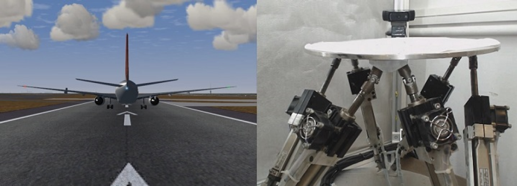
In this study, a desktop flight simulation system is introduced with components including flight simulation software, a desktop-parallel robotic manipulator and a motion-cueing system. Human motion perception is summarized. Inverse/forward kinematics of the system and the real-time solution is explained. The communication problem between the simulation and the platform is addressed and, finally, the results from the hardware are discussed. The hardware used in the simulation and the real-time experiments is summarized in Figure 1.
The parallel robotic system as a simulator has six DoF—three translational and three rotational motions. It was first designed in 1965 by D. Stewart, and mounts top and bottom plates and connects with six parallel legs that move linearly [30].
The flight simulator components are:
Simulated vehicle
Visual feedback system
Vehicle control system
Motion simulator
Actuators and drivers
Sensors
Motion-perception software
Motion-cueing algorithm
Human perception model
Flight simulation software
Simulators have a visual interface on which the simulation of aircraft motion is performed. In this study, FlightGear 3.4 flight simulation software is used, which is an open-source software including several aircraft models. Because of the heavy workload of flight simulation, separate processors are allocated on separate computers to generate flight data, control signals and visual feedback of the flight. An HP z230 workstation computer with eight GB RAM and Nvidia NVS 510 video card with four display ports are used to obtain uninterrupted visual flight feedback.
Motion simulator
The system is on a 6×6 parallel desktop manipulator and is driven by linear DC motors (Linmot PS01-23X80 / 0150-1201). Linear motors have a motion capacity of 110 mm; multi-axis motion control of the motors is performed via Linmot E210-VF model motor drivers, Figure 2. Figure 3 illustrates the joystick used and the flight simulation software.

Motion system block diagram

(a) Flight simulation software (b) joystick (Thrustmaster Hotas Warthog)
Because the internal control algorithms of linear motor drivers are extensively active in velocity mode, the force mode of drivers is selected so the authors can apply external control algorithms effectively. Position data are obtained via internal linear encoders of the motors with a sensitivity of 10 μm. Platform parameters are listed in Table 1.
Parameters of 6×6 parallel manipulator mechanism

In flight simulators, all linear actuators are driven simultaneously to move the six DoF (x, y, z—roll, pitch, yaw) parallel manipulator to any desired position. Required positions of actuators are recalculated at each sampling time and the position error of the legs is kept to a minimum. The major issue in flight simulators is that the software has infinite space and platform has a limited one. A washout filter used in the motion-cueing algorithm eliminates this issue, which constrains the position data the platform receives and, most importantly, attempts to move the platform to its initial position under the driver's perception of motion level.
The motion perception algorithm consisting of high-pass and low-pass filters is applied to reduce the translational acceleration and angular velocity values obtained from the FlightGear flight simulation software via a communication protocol to an acceptable limit of the platform workspace. Translational accelerations are filtered from high-frequency data and noise using a third-order (first-order high-pass washout and second-order low-pass washout) filter and angular velocities are filtered from high-frequency data and noise by a second-order washout filter.
As shown in Figure 4, the translational motion channel is responsible for simulating the aircraft translational motion. The channel's input is the translational acceleration of the aircraft in the flight simulation software. The rotational motion channel simulates the aircraft rotations. Its input is the angular velocity of the aircraft. The tilt-coordination channel uses a tilt-coordination algorithm to estimate aircraft inertia along x and y axis. The output of this channel is summed with the rotational motion channel establishing the final rotational cue.
Filtered signals are transmitted to motor drivers, taking the double integrals of translational acceleration inputs and the single integral of the angular velocity inputs, creating position information via the platform's inverse kinematics.

Motion perception structure for a flight simulator
Platform velocity is kept lower than the human perception level during the washout process. Thus the pilot does not feel the washout motion presence. The combination of movement creates a real flight feeling. As shown in Figure 5, the classical algorithm has a simple structure, yet it is not adaptive due to its constant parameters.
In the algorithm, the first-order high-pass filter is as follows:

The second-order high-pass filter is:

The first-order low-pass filter is:

ζ is the damping ratio of the second-order filter. In this study, the damping ratio is one. If necessary, this factor can be reduced.

Motion-cueing realization for x-axis motion
ω is the filters' corner frequency. In this experimental study, the factor is chosen according to the system performance and platform workspace boundaries.
Figure 6 illustrates the tilt effect used to simulate translation acceleration using the rotational motion of the platform while the platform is motionless. Since motion simulators tend to have limited workspace, it is necessary to simulate translational acceleration using the Earth's gravity and rotational motion of the platform when the platform is motionless. In a motion-cueing algorithm, the tilt coordination formulation can be shown as:
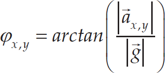
In Figure 6, the aircraft accelerates along the x axis and is tilted about y axis. φ x and φ y are the tilt angles of platform. a x,y shows acceleration in the x and y directions of the platform and g is the Earth's gravity. Since the tilt effect is a low-frequency motion, the simulation of translational acceleration can be easily simulated by using the Earth's gravity [31]. However, high-frequency acceleration is simulated by the translational motion of the platform. The axes of the aircraft are represented in Figure 7.
The human perception system is the basis for human perception studies. The vestibular system is shown in Figure 8. The dynamics between sensed angular velocities,

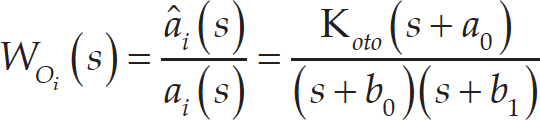
In the transfer function between translational acceleration sensed in the ear,

Tilt effect on platform caused by acceleration on x axis

Motion axes of the aircraft
a0, 1/τ1 is b0 and 1/τ2 is b1 by using time-constant coefficients of otoliths. K oto is the gain of the system.
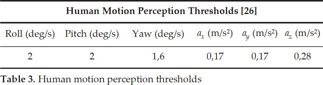
Index i shows the rotational motions in Euler angles (roll, pitch, yaw). Human motion perception system parameters are shown in Table 2 and human motion perception threshold parameters are shown in Table 3.
A human detects acceleration and angular motion through the inner ear's vestibular system. Because of insensitivity at low speeds, motion perception algorithms simulate the acceleration of the platform and attempt to return the platform to its initial position at these low speeds. When high frequency motion signals move the platform, low frequency motion signals are transformed into angular motion. The major issue in this motion is the loss of the acceleration's low-frequency content. To eliminate this issue, the idea of tilt coordination was developed. The gravitational acceleration is g = 9.78033 m/s2 which is the z component of the gravity vector. If an amount of roll motion is given as input to the simulator, the x component of the gravity vector can be adjusted to the level of the pilot's motion perception.
Human motion perception model coeff.

Human motion perception thresholds

Relationship between vestibular system and human perception
As in serial robots, kinematic analysis of parallel mechanisms should be examined in terms of inverse and forward kinematics. Inverse kinematic analysis helps to find the leg lengths, (L1, L2, L3, L4, L5, L6), given the position and orientation of the end effector when the position and rotation of top plate, (x, y, z, α, β, γ), is known. Forward kinematics is the problem of finding the position and orientation of the top plate with respect to the fixed base when the leg lengths are known. Forward kinematics analysis is important in terms of all the conditions the platform may have in specific leg lengths. The contrast between serial and parallel robots continues here. When a specific trajectory need to be followed, it is necessary to solve the inverse kinematics in real time. The forward kinematics solution of a parallel mechanism is not unique in that there are several possible configurations of leg lengths. In inverse kinematics, the solution is unique, which means one position/orientation of the top plate refers to certain leg lengths.
Inverse kinematic analysis
Inverse kinematic analysis for parallel mechanisms is simple to solve compared to forward kinematics. Inverse kinematics of a robotic system can be used to plan a specified trajectory that uses leg lengths by providing any specified position of the centre of the platform top plate. The platform is shown in Figure 9.
{P} demonstrates the position of the centre of gravity of the top plate and {B} demonstrates the position of the centre of gravity of the bottom plate. Λ can be defined as the angle between the forthrights drawn from the origin of axes, {B}, to successive two corners of the fixed plate. λ is the angle between forthrights drawn from the origin of axes, {P}, to two successive corners of the moving plate.


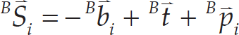
The position of points P
i
are defined by equation (7) and position of B
i
points by equation (8). Leg length l
i
can be obtained by calculating the magnitude of the


Experimental system and modelling of the parallel manipulator
By integrating (9) into (11), the leg lengths are calculated according to the translation and rotation of the top plate. After successive regulations, the final inverse kinematics equation is obtained as follows:

There are several approaches on forward kinematics solutions in the literature. In this study, Newton–Raphson method is used and an equation in the form of F(x) = 0 is solved.
In this equation, x0 is considered as initial point and if F(x) has a derivative at x0, the tangent of the function at related point can be expressed as follows:

Next, x 1 can be found by replacing x in the equation and zero instead of Y.


x1 in equation (16) will be closer to the solution. To achieve a more absolute solution with the same method, iterations are applied and solutions of x 1 , x 2 , x 3 …x n can be obtained. When the desired solution sensitivity is reached, iterations are terminated.
For the forward kinematics solution of the Stewart platform mechanism, Newton-Raphson method is applied as follows:
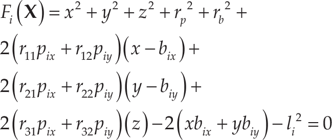

Because the function contains more than one variable, the derivative of the function used in Newton-Raphson method can be found by taking the partial derivative for each variable as follows:
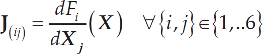
Then, the unknowns are calculated by the following equation:

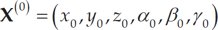
The initial conditions are:
As a result of this iterative approach, a sufficiently accurate result is obtained. When approaching the solution, an ɛ value of sufficient accuracy should be defined as:
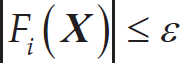
When equation (21) is confirmed, the iterations are terminated and last
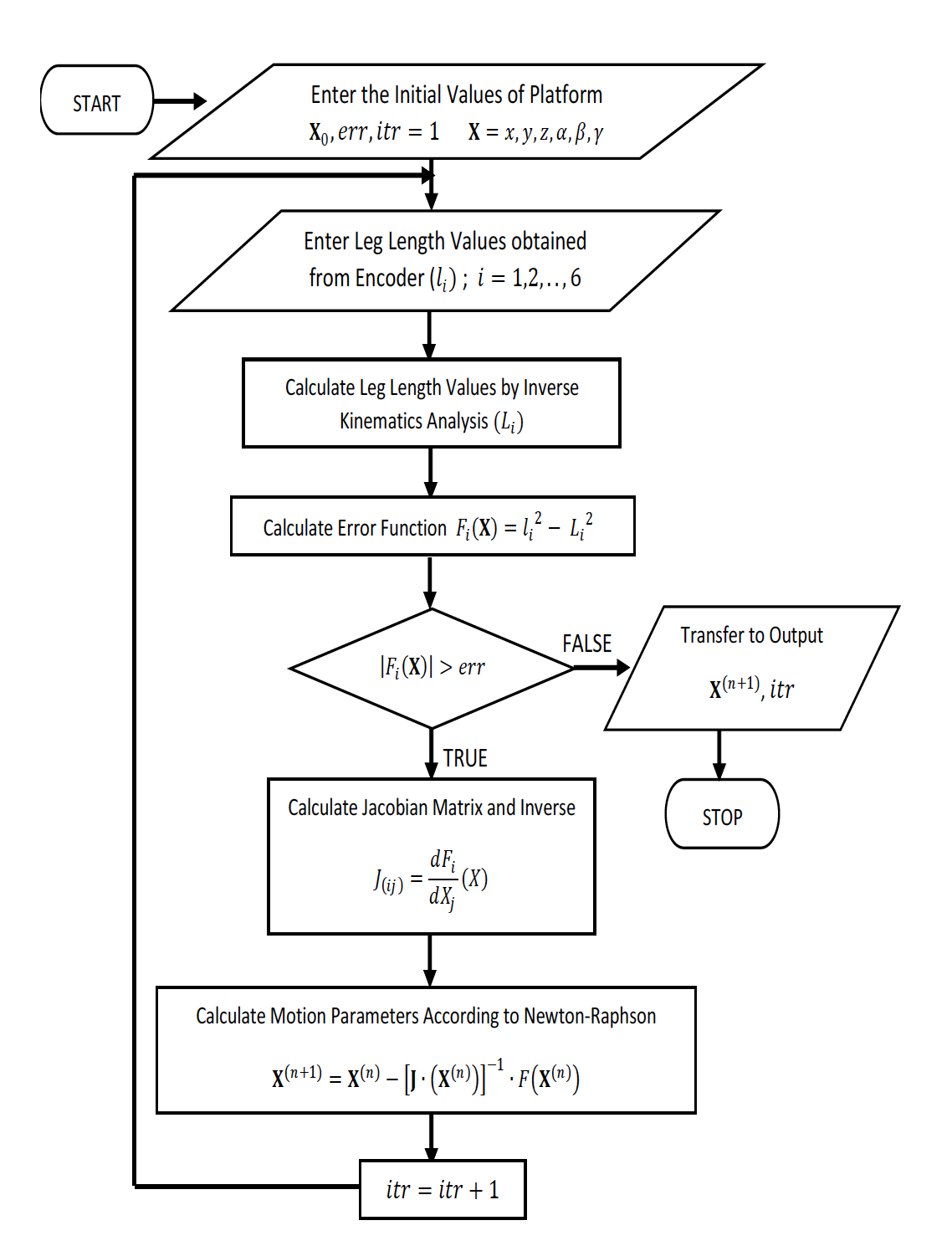
Flowchart of forward kinematics analysis [30]
To maintain signal transmissions between control/flight computers and the simulator in real time, the system's communication is treated to preserve true motion feeling. Flight data is fed to the control computer to generate the necessary trajectories of the platform based on motion-cueing algorithms [32].
Communication and software
The mathematical model of the simulated aircraft is hidden in the visual simulation software, FlightGear, and the motion of the aircraft is commanded using an external professional joystick system. These mathematical models produce motion variables for the flight, which are transferred to the control computer. A generic protocol is used on the input/output port of the visual simulation software. The flight parameters produced by the flight simulation software's mathematical models are transmitted via generic protocol as data packages and delivered into the platform control computer employing the TCP/IP protocol. During this process, data to be transmitted are defined by creating an XML script file. Thus, six parameters including translational accelerations of the simulated aircraft at different pilot positions and angular velocities are transmitted to an external port (Table 4).
FlightGear sample data output

FlightGear sample data output
The created XML script is kept in the visual simulation software's setup folder and is run here in real time. The XML script is shown in Figure 11.

XML script file and last expression
It is determined that a sampling frequency of 240 Hz is sufficient for visual simulation. Thus, the visual simulation external communication frequency is chosen to be 120 Hz based on the Nyquist criterion. Flight data obtained from the flight simulation software are transmitted to the defined port of motion control computer via a TCP/IP protocol (Figure 12). A server in an m-File is created to receive incoming data in a Matlab environment.

TCP/IP Protocol connection codes
Received data should be transformed into an appropriate format in the control computer's Matlab environment. Incoming data obtained as a result of the transformation process are first extracted then assigned into an array to perform the transformation process. Members of this array are transmitted to the simulator control model in a Simulink environment in real time as aircraft motion parameters. The final part of the protocol is the format variation code structure, which is shown in Figure 13.

Format variation code
The parallel manipulator is controlled in two stages:
Force (current) control of linear actuator drivers
Individual leg position PID controllers implemented in a Simulink control model over the Q8 card
The overall structure of the control model is represented in Figure 14, in which each leg's control signal is generated and fed separately. The output of the PID controller is an analogue input to the motor drivers as ±10 V, which is considered to be a current set point since the drivers are used in force-control mode. The linear actuator inner control model is shown in Figure 15. This input relationship is shown in Figure 16. Thus, ±10 V refers to ±3A in the driver controller, which results in force control over the linear actuator. Drivers of the linear actuators are set to provide auxiliary encoder output in 10 μ resolution (over the possibilities of 1, 5, 10, 20 and 50 μ), which provides the best performance for the setup used. Since set points regarding FlightGear data is compared with actual encoder readings, the difference between them is considered to be the error supplied to the controller structure. Flight Simulation by FlightGear 3.4 can be run in 5–10 Hz; 5 Hz is employed in this application because of the general acceptance by JAR standards for level D simulators.
Because of the nonlinearity and complexity of the platform kinematics, PID parameters are selected based on Table 6.

Simulink model of the simulator

Linear actuator driver control model
Platform mathematical model controller coefficients

Coefficient properties of PID

Washout filter parameters are chosen as in Table 7 using trial-and-error method in which 18 parameters are present and motion range, limited workspace, obtaining logical motion behaviour and the security of the platform are the considerations. By varying the parameters with small intervals, the motion of the platform has been observed and best results are chosen based on above criteria.
Simulation tests are performed on the desktop simulator system. Boeing 777-300ER model aircraft is prepared for departure from a specified airport in FlightGear 3.4 visual simulation software. The acceleration effect on the aircraft during departure is simulated as an amount of motion in the x-axis (forward) direction (Figure 17).
The aircraft moved through x axis with 4 m/s2 acceleration and the platform moved 0.08 metres through x direction. The platform rotated 8° about the y axis simultaneously because of the tilt coordination to simulate continuing forward acceleration using a gravitational effect. The results are as shown in Figure 18.

Relationship between analogue input and supply current
Washout filter parameters of classical algorithm

Motion at 20th second
In the second case, the aircraft performed roll motion and moved about the x axis through a CCW direction with an alpha angle of −5° (Fig. 19). Then the following motion about the clockwise direction with a 7° alpha angle (Fig. 20) is performed. Results are as shown in Figure 21 and Figure 22.
In the third case, the aircraft descended with an angle of 10° about the y axis (Fig. 23.) and lifted its nose with 15° about the y axis (Fig. 24.). Results are as shown in Figure 25. In this motion, the platform moved through z axis for perceived g-force of aircraft. The platform moved −0.05 metres when the aircraft dived. Secondly, the platform moved 0.1 metres in a z direction when the aircraft lifted its nose.

Aircraft acceleration, filtered acceleration and platform motion

52nd second of flight, roll motion about anticlockwise

Motion at 56th second
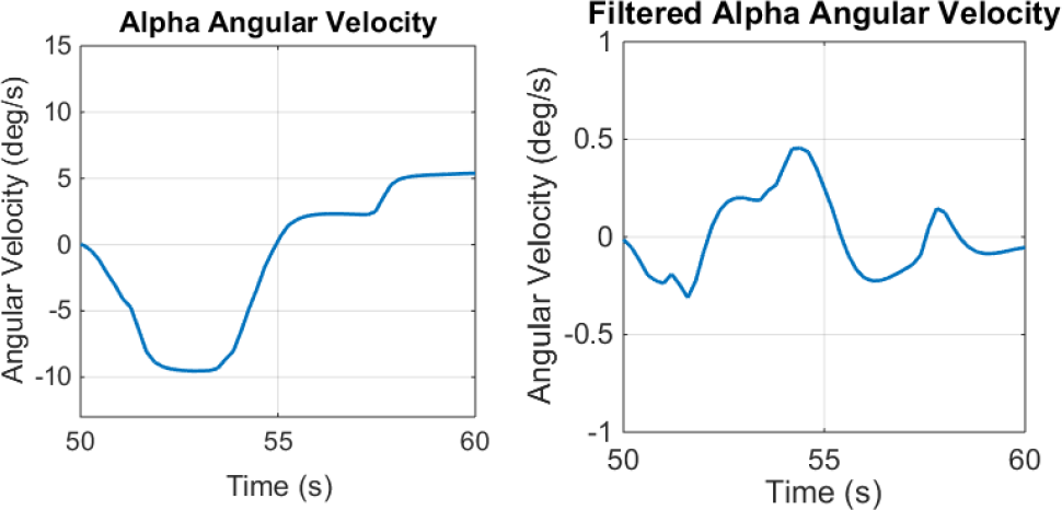
Angular velocity and filtered velocity of the aircraft
The results of the simulation on a desktop simulator are considered to be satisfactory and the desktop system is proven to be more economic to use in trials of various washout filters. As a further analysis, the pilot's perception of motion is to be analysed using the provided vestibular model and forward kinematics of the platform. Since the results obtained are based on a classical washout algorithm, further investigation is to be performed using extensive algorithms like adaptive, optimal and model predictive washout structures.

Rolling performance of platform

Motion at 167th second

Motion at 169th second

Diving and lifting-nose accelerations of the aircraft and motion of the platform
This paper presents a novel and economical desktop flight simulator system. When compared to similar systems, it can be seen that the proposed system is more convenient for motion-cueing studies because it is simple and economic to apply developed motion-cueing algorithms.
The FlightGear package programme uses XML as a data protocol to provide communication between FlightGear and MATLAB via TCP/IP protocol so an XML script file is necessary for this system.
The development of other motion-cueing methods (optimal, model predictive, adaptive) is also being performed using this system. The main goal is to optimize the algorithm giving the best results to use in a full flight simulator system (FFS, Level D), which is already constructed and in use.
Footnotes
Acknowledgements
This article is a revised and expanded version of a paper entitled Experimental Motion Cueing Studies Employing Desktop Flight Simulation System presented at 14thInternational Conference on Circuits, Systems, Electronics, Control & Signal Processing (CSECS '15), Konya, 2015. This work is supported by the Ministry of Science, Industry and Technology of Turkey under grant 0563.STZ.2013-2 and by Scientific and Technological Research Council of Turkey, TUBITAK. The information provided in this article does not reflect the ideas of the Ministry.