
Abstract
This paper summarizes the development of a robotic system for the analysis of aircraft dynamics within and beyond the nominal flight envelope. The paper proposes the development of a parallel robot and its motion cueing algorithm to attain a reasonable workspace with adequate motion capabilities to facilitate the testing of aircraft stall and fault manoeuvrability scenarios. The proposed design combines two parallel mechanisms and aims to provide six degrees of freedom motion with a much larger motion envelope than the conventional hexapods in order to realize the manoeuvrability matching of aircraft dynamics near and beyond the upset flight envelopes. Finally the paper draws a comparative evaluation of motion capabilities between the proposed motion platform and a conventional hexapod based on Stewart configuration in order to emphasize the significance of the design proposed herein.
Keywords
1. Introduction
In recent years, with a great number of fatal aircraft accidents and failures, investigations to prevent these fatalities have become of great importance for the research community. Typically, aircraft accidents are attributed to aircraft loss-of-control [1] that may involve sensor failure, actuator failure or pilot errors. Upon losing control, the aircraft may quickly deviate beyond the nominal flight envelope into a disturbed condition, causing control to become even more difficult [1–2]. As a consequence, the analysis of aircraft dynamics near and beyond the nominal flight envelope is a focus of extensive research nowadays. Aircraft dynamics have already been well established for cruise and glide scenarios [3–10] through various methodologies for the analysis under these nominal conditions. However, specific circumstances beyond the nominal or safe flight envelope have not been investigated in as much detail so far.
In order to understand and devise methodologies for the prevention of loss-of-control situations, we aim to develop a robotic-test-bed that may include a dynamically scaled aircraft cabin [11] for exploring the dynamics and control of general transport aircraft. In order to obtain the experimental model of a transport aircraft, we capture the complex nonlinear behaviour of a Boeing 777-200 within and outside the nominal flight envelope using X-Plane (a commercially available flight simulator package), a versatile tool that allows engineers to explore the behaviour of aircraft dynamics under nominal and abnormal flight conditions. Though extremely useful, the X-plane package does not provide closed-form equations that represent the dynamics of the aircraft, however, it outputs flight data with practical environmental conditions at real-time, providing an effective opportunity to conduct real-time hardware-in-loop simulations. Therefore, we use the flight data obtained from X-plane as reference input to simulate our proposed dynamical model for manoeuvrability matching.
In-flight simulations are considered to be one of the most reliable and practical ways for the evaluation of the manoeuvrability of an aircraft, that is required to simulate nominal and abnormal flight scenarios. Thus, the goal of this paper is to propose a robotic system (a multi-DOF motion platform), that achieves the desired manoeuvrability matching under nominal and upset flight situations in the presence of environmental disturbances (gust disturbance) which are inevitable in the real world.
The rest of the paper is structured as follows: after a description of our proposed design of the motion platform in section 2, the mathematical modelling is described with the aid of forward/inverse kinematic model. Section 3 provides a brief overview of a real-time simulation model and our motion cueing framework using SimMechanics and Simulink. Section 4 provides the results of closed-loop dynamic simulations and analysis performed for a test flight plan. Concluding remarks are given in section 5.
Literature Review and Related Work
Most of motion platforms found in literature are typically based on Stewart configurations [12]-[17]. Though these typical hexapod configurations provide 6-DOF motion however, these motion platforms suffer from their limited motion envelope and because of their motion constraints imposed by the closed kinematic chains they are incapable of achieving large linear and angular accelerations and rates. Researchers have also studied parallel manipulators with less than six legs [36] & [37] to reduce interference between links and simplify the forward kinematics problem.
In contrast, the strategy of exploiting serial manipulators as motion platforms has drawn attention for possible improvement in the motion envelopes [18–24]. Though, a serial six DOF manipulator provides large motion workspace, higher dexterity and the capability to carry heavy loads with much higher accelerations and velocities in comparison to parallel robots. However, exploiting serial manipulators as motion platforms for flight simulation also involves issues such as the unavailability of appropriate kinematic solution and washout filters [25].
In the past few years researchers have proposed double parallel manipulators [11, 12] which are designed with a central axis stacking the two parallel mechanisms. The motion of each parallel mechanism is decoupled and restricted by a common central axis to enlarge workspace and avoid singularities [33]. Generally in a double parallel manipulator each parallel mechanism with two or three linear actuators independently generates the positional or orientation workspace to reduce the interference between links enlarging a compound positional workspace as a consequence. The architecture of a double parallel mechanism is quite different from a conventional Stewart-Gough platform and there are many problems related to the formulation of its kinematics and dynamics which still require further research and investigations.
Another related study [34] describes a double parallel mechanism with its kinematics and addresses the main issues related to the design and manufacturing of double parallel mechanisms. For example, the design of a spline shaft of the central axis which resists torsion loads involves the force and moment analysis at its passive joints which is quite complicated.
A much more recent research study [35] has described a new attempt to facilitate the practical usage of a double parallel robot by proposing different combinations of the two parallel mechanisms. A composite six DOF parallel robot is introduced which is a composition of one planar 3-RPR mechanism and another 3-UPS mechanism, combined together using a serial connection. Although these research studies propose a robotic platform with a remarkable advantage in the compound positional workspace compared with the conventional Stewart-Gough platform, the double parallel robots are a little too far away from the parallelism to take advantage of the large workspace, but compromise on the stiffness. Moreover, the torsion stiffness is very serious in actual practice and must be improved for a better architecture.
Therefore, here we aim to propose the closed-loop control of a motion platform comprised of hybrid architecture with an attempt to achieve a reasonable motion envelope which conventional hexapods are incapable of achieving. Although our approach can be applied to a large number of vehicles and aircraft dynamics with some changes, we selected the flight dynamical model of a turbo jet airplane (Boeing 777-200) as a testing scenario for obtaining experimental evaluation through dynamic simulations.
2. Design and Modelling
This section outlines the basic kinematic architecture of our proposed design perceived from the double parallel mechanism idea and develops the forward/inverse kinematic solution for a real-time motion cueing algorithm.
2.1 Architecture of Motion Platform
The architecture consists of a ground plate represented by a fixed coordinate system and a motion plate represented by a moveable plane in 3D space. Joints G1-G6 belong to the ground plate and are actuated revolute joints. Joints M1-M6 belong to the motion plate and are also actuated revolute joints. The motion plate is connected to the ground plate through six actuators forming a closed kinematic chain, further illustrated in Figure 1. The joints B1-B6 are passive universal joints.

Model of the Proposed Motion Platform
The novelty of the structure lies in the kinematic configuration of this composite architecture (combination of two parallel mechanisms) using a leg design that is composed of two parts: the upper part of the leg constitutes a linear actuator with one actuated revolute joint (θe) and one actuated prismatic joint (le) while the lower part of the leg constitutes a three DOF serial manipulator with two actuated revolute joints (θb, θc) with their motion axes sharing a common plane, further illustrated in Figure 2. The selection of the joints on the ground plate and the moveable plate is based upon the research study conducted in [11].
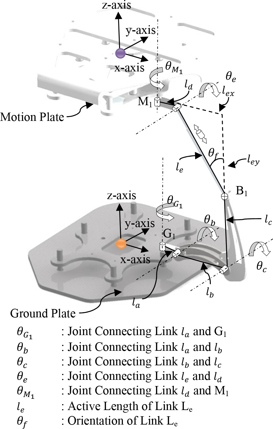
Kinematic Configuration of a single actuator
2.2 Mathematical Model
The objective here is to determine the forward and inverse kinematic equations of the proposed kinematic structure so as to find the appropriate joint rotation angles and active lengths of linear actuators for a required pose.
2.2.1. Forward Kinematic Model
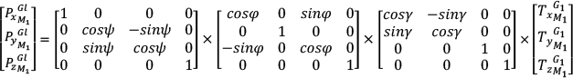
From Fig. 2, the position of M1 joint on the motion plate with respect to the ground plate coordinate system can be obtained using homogeneous transformation matrices and Denavit-Hartenberg convention as given by (1).

Where,


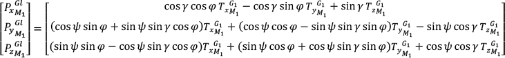
Substituting (3) & (5) into (1) yields the position of M1 with respect to G1 as given by (6)

In order to completely describe the moving points Mi of the motion plate in the global frame of reference, the angular rotations of the motion plate in 3D space must be brought into consideration. Body rotations about the three axes are set as shown in Fig. 1 where, psi(ψ) is the rotation of the motion plate about global x-axis and is termed as pitch, gamma(γ) is the rotation of the motion plate about global z-axis and is termed as yaw and phi(φ) is the rotation of the motion plate about global y-axis and is termed as roll. Using general homogenous transformation matrices, the position of a moving point M1 on the motion plate in the global frame of reference can be expressed by (7) which can be further simplified to (8). In global frame of reference, let ψ, φ, γ represent the rotation of motion plate about x-axis, y-axis and z-axis respectively. Thus, the transformation from the moveable frame of reference to the global frame of reference can be described by a homogeneous transformation expression (pitch-roll-yaw orientation) as given by (9).

2.2.1 Inverse Kinematic Model
The objective of the inverse kinematic model is to determine the appropriate joint rotation angles in order to achieve the desired motion of the motion plate. Joint angles of a leg are computed using the manipulator inverse kinematic equations as described by (10) and (11).
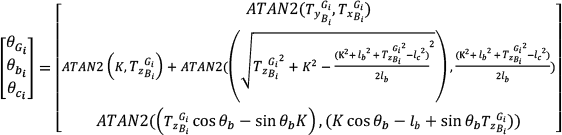

Where,
In order to actuate the prismatic joint in each leg, its active length le can be obtained from the expression given in (12).

Where,
3. Simulation Model with Motion Cueing
The goal and contribution of this section is to describe a closed-loop simulation setup with a motion cueing algorithm in order to generate reference motion trajectories over the motion platform via the kinematics described earlier. Through literature review [19, 20, 25 & 26], it is well understood that motion cueing algorithms using wash out filters have been designed to filter the motion of a high fidelity dynamical model to adequate levels so as to make the motion profiles compatible for a given workspace. Typically the algorithms related to washout filters with tilt-coordination methods are used for reproducing low-frequency motions using control frameworks [23–32]. These methods are considered to be the only feasible alternative as motion cueing algorithm and are still considered to be the most effective because of their design simplicity, robustness and implementation. Their working is as follows: aircraft dynamics specified in terms of rates and accelerations is split into components of high and low bands, simulating the platform with the high-frequency components and exploiting the local gravity vector to realize persistent acceleration that is not achievable otherwise [25]. However, due to the motion limits of motion platform, it is realistically impossible to reproduce sustained accelerations larger than 1g and angular motions beyond the rotational motion limits of the motion platform. The simulation model as shown in Figure 5 captures the complex nonlinear behaviour of the aircraft within and beyond the aircraft's nominal flight envelope and simulates the captured motion cues over the motion platform for advanced simulation, testing and analysis of generic flight dynamics under non-ideal circumstances. The physical model of the motion platform as shown in Figure 4 is translated from its CAD form into Simulink using SimMechanics toolbox.

Views of the motion platform in different poses.

A) Physical model of the overall motion platform. B) Physical model of a single leg.
By exploiting the roll-rotations of both the motion and the virtual planes, large roll angles and rates can be obtained along angular trajectories. Similar can be achieved with the pitch and yaw rotations in the angular trajectories and heave, surge sway along the translational trajectories. Using the previously described kinematics model, our proposed motion cueing scheme is illustrated in Figure. 5. The linear accelerations of the aircraft [ẍiA, ÿiA, z̈iA]
T
are passed through a high-pass filter. These linear accelerations expressed in the aircraft frame of reference are first scaled to obtain
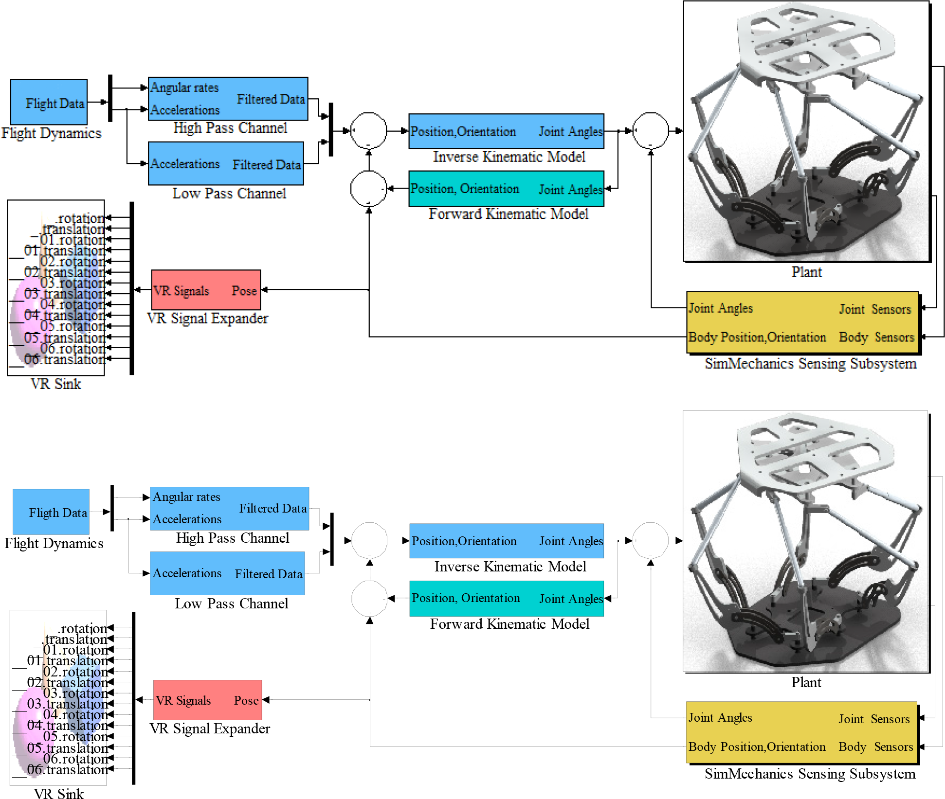
Block diagram representation of our motion cueing framework.
4. Experimental Evaluation and Results
The flight dynamical model of an aircraft (B777-200) suitable for a Level-D type flight simulator was first simulated in real-time over a conventional hexapod (Moog 6-DOF2000E) using the simulation model described in Figure 6. Figure 7 shows a view of a conventional hexapod in SimMechanics environment while, Table 1 enlists its motion specifications. In the second run, the same test was repeated using the simulation model of our proposed motion platform. The main focus of this work is to evaluate the motion capabilities of our proposed robotic setup for the functional evaluation of aircraft dynamics beyond the nominal flight envelopes, therefore, the data acquisition methods are not discussed here in detail. In summary, data acquisition was achieved using serial interface RS-232 from sensors and UDP interface for inter-network data processing.
Motion specifications of Moog 6-DOF 2000E[33].


Simulation model of a conventional hexapod (Stewart-Gough configuration with linear actuators).

A view of a conventional hexapod in SimMechanics.
The abnormal scenario for testing was chosen as follows. A normal trim condition was found at a low-speed (52 knots) cruise condition, with a zero flight path angle. Because 52 knots is at the low end of the nominal safe speed for a B777-200 cruise flight, decreasing the speed or increasing the angle-of-attack at this condition induces a fault scenario. To generate a fault condition during the simulation, a control surface failure was replicated by first locking the elevator at −3.2 degrees beyond the desired trim condition followed by the failure of the aircraft's left aileron. The failure trajectory was first simulated over a standard hexapod and then using our proposed motion platform in real-time for manoeuvrability matching and comparative analysis. The trim condition for the low speed near-fault cruise flight was specified by the simulation model as described in Table 2.
Trim conditions for the tested fault scenario

The fault was simulated as follows: at 70 seconds into the flight, the elevator control surface failure occurred causing the elevator to lock at 5.1°, that is 3.09° beyond the nominal trim condition. The resulting simulation showed that after the failure the aircraft first tilted upwards with an increased angle-of-attack causing the aircraft to stall for about 55 seconds and then unexpectedly roll towards its right followed with a decreasing pitch angle. By three minutes into the simulation, the aircraft headed towards a crash under these abnormal flight conditions. Using the real-time X-Plane 3D animations in conjunction with the Simulink simulation model, Fig. 14 illustrates the graphical representation of the extreme behaviour of the aircraft along the fault trajectory.
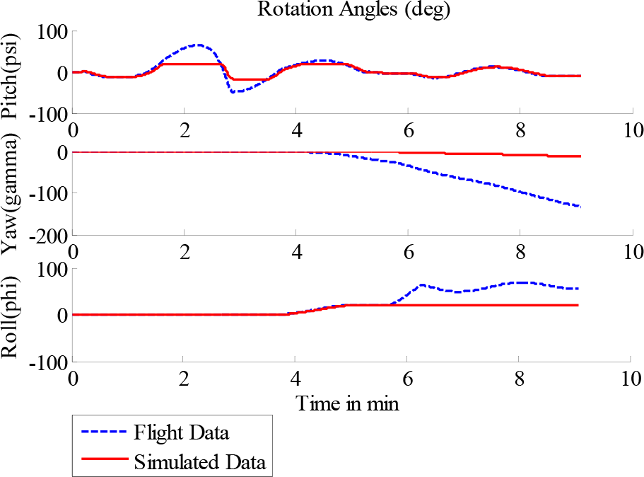
Comparison of rotation angles
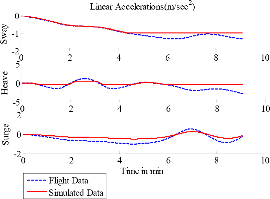
Comparison of linear accelerations.

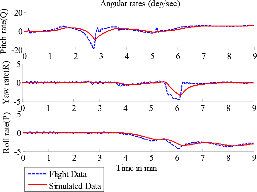
Comparison of angular velocities.

Comparison of rotation angles in the second test.

Comparison of linear accelerations in the second test.
Comparison of angular velocities in the second test.

Graphical representation of the fault flight scenario simulated using a standard hexapod.
Figures 8, 9 and 10 show the plots of various flight parameters for the simulated fault flight scenario. As apparent from the figures, the system maintained trim conditions from t = 0 to t = 20 seconds, before the fault was induced. The locked-elevator fault was induced at about t = 70 seconds causing the aircraft to gain pitch angle. Since the set throttle (30%) was insufficient to provide the aircraft with the necessary lift, the pitching-up situation continues without vertical lift for about the next 25 seconds causing the aircraft to stall. The decreasing pitch angle as shown in Figure 8 shows that the autopilot tried to recover the aircraft from the stall situation, but unexpectedly the failure of the aircraft's left aileron subjected the aircraft to an abrupt roll towards the left which is evident from the increasing roll angle's profile as shown in Figure 8.
The comparative analysis of the reference flight data and the actual simulated data returned by the onboard sensors explain that the hexapod was unable to simulate the required pitch angle during the stall situation since the maximum attainable pitch by the hexapod was 22° as illustrated in Table. 1. Similarly, during the complex motions, the solid plots in Figures 8, 9 and 10 clearly exhibit that the simulated motion cues do not match the reference flight data. Thus, the hexapod was found to be inefficient in investigating and realizing such a fault flight situation at low speed.
In contrast, the real-time simulations carried out using the simulation model of our proposed design with its motion cueing framework resulted in significant improvement in manoeuvrability matching as apparent from Figures 11, 12 and 13. The close matching of the reference flight data and the simulated motion cues over the motion plate concludes that the proposed kinematic architecture is suitable for simulating flight scenarios with disturbed situations requiring large motion envelopes and improved dexterity. As apparent from Figure 11, the motion platform was able to simulate the high pitch angle during the stall scenario and was also successful at simulating the extreme roll angles near the final crash.
5. Conclusions and Future Work
This paper presents a complete framework for the development a multi-DOF motion platform using the characteristics of a hybrid kinematic configuration. The chief inspiration behind this work is an effort to design a motion platform which may offer a much larger motion envelope in comparison to standard Stewart platform with an opportunity to simulate any potential cabin posture possible within its, an attempt to simulate abnormal flight scenarios which require these enlarged workspaces. This evidently signifies a promising perspective for appliance of motion simulators in the analysis and investigation of aircraft dynamics during upset conditions. In order to take full benefit of such a kinematic architecture, the requirement of a unique inverse kinematic approach and the development of a motion-cueing framework customized to the particular kinematic design was also our focus in this paper.
Simulations were carried out using the proposed motion cueing system in an upset flight scenario. This flight scenario involved challenges namely: extreme pitch and roll rotations and unexpected rates during stall situations. The performance of the controller has been found satisfactory as validated by the comparative analysis of the motion cues simulated by the motion platform and the reference input. The design proposed in this paper is still subject to several enhancements which include the incorporation of an adaptive control algorithm for the cautious regulation of the motion-cueing system to further enhance simulation realism. The development of the first actual prototype and the construction of a closed cabin with a cockpit have been planned and under future work which is anticipated to contribute in the overall improvement of the simulation fidelity.
Footnotes
6. Acknowledgments
The authors would like to thank the anonymous reviewers for their detailed and pertinent comments.