
Abstract
Humanoid robots are versatile robot platforms that can carry out intelligent tasks and services for humans, including intimate interactions. For high mobility, a robust stabilization of motion including biped walking is crucial. This paper employs and elaborates on sensory reflex control to stabilize standing motion and biped walking using basic sensors such as an inertial measurement unit (IMU) and a force-sensing resistor (FSR). Specifically, normalized zero-moment points processed from FSR data are used in the reflexive control of a simple motion of swinging the whole body while standing, and the measured inclination angle of the trunk, filtered from IMU data, is used for biped walking on a sloped floor. The proposed control scheme is validated through experiments with the commercial humanoid robot, ROBOTIS-OP.
Keywords
1. Introduction
Humanoid robots are designed and manufactured to resemble the human body, which is advantageous for providing effective human and robot interaction (HRI), intelligent services and displaying emotions through expression. Considering the scope of tasks to be carried out by humanoid robots, motion stability must be guaranteed irrespective of motion types, including dynamic motion like biped walking and static motion such as providing a food plate to people while standing.
Most research on the stability control of humanoid robots has concentrated on biped walking from two perspectives: pattern generation and motion stabilization control. The pattern generation of walking is conducted offline using the stability principle with a zero-moment point (ZMP) [1, 2] and a human-like two-stage gait pattern generation [3]. Motion stabilization control employs an inverted pendulum control [4], a central pattern generator [5], neural networks [6] and a fuzzy control [7] for the real-time adjustment of joint angles during biped walking, using all the sensory information available.
Despite the fact that the humanoid robot spends the majority of the time performing various tasks while standing erect, stability control for static motion has rarely been studied with experimental validation.
Sensory reflex control (SRC) is an inclusive and nature-inspired control strategy combining pattern generation and feedback control with a sensory reflex [8]. The analysis of humans' natural walking method has been verified as an elegant mixture of inherent efficient patterns and rapid reflexive actions. Li et al. improved SRC by planning the ZMP trajectory and designing dynamic balance control with sensor fusion and fuzzy logic [9]. However, 10 joint actuators installed in the legs were controlled by single sensory information, which limited the control and performance of walking.
In this paper, two types of SRCs—one based on ZMP and the other on trunk inclination angles—are proposed with novel control schemes to stabilize humanoid motion while standing and during biped walking. The standing motion is to swing the whole body back and forth by rotating just the ankle joints following a sinusoidal trajectory. Since the magnitude of the body swing angle is 10° with a high velocity, the robot may fall down uncontrollably. ZMP-based SRC (ZSRC) is applied to this standing motion by limiting the ankle joint inside the marginal angles measured by ZMP and adjusting the knee and hip joints in a stabilizing direction.
As for the biped walking, reference joint patterns are generated offline for the robot to walk on level ground using an optimization method, which traces the referent ZMP trajectory and swing foot trajectory [10]. Humanoid robots often walk on a slightly inclined road or office floor, which requires minute changes in leg joint angles according to the inclination. During biped walking, ZMP dynamically flows in compliance with the walking direction and rightward or leftward according to the current supporting foot. Therefore, pitch and roll angles of the trunk are used in the application of SRC to the adaptation of both ankle and hip joints during walking on an inclined floor. The humanoid robot platform used in this paper is ROBOTIS-OP, a commercial, small humanoid robot, with which motion experiments are carried out with and without SRC for validation of the proposed control scheme.
This paper is composed of six sections; Section 2 introduces the SRC and the measurement of posture stability using FSR. Section 3 describes the optimal pattern generation of biped walking and, employing a global optimization method, uses reference ZMP and foot position trajectories. In Section 4, the proposed SRC based on ZMP and trunk angle are explained with control principles and equations. Section 5 provides experiment results for the two types of SRC, and Section 6 concludes the present work.
2. Motion Stabilization Control
2.1. Sensory reflex control
In everyday life, humans balance the whole body skilfully with the rapid coordination of the spinal cord as a controller, the cochlea as an inclination sensor, and lots of muscles as actuators. SRC mimics this balancing principle in that the dynamic motion pattern,

Structure of the sensory reflex control for a humanoid robot

When SRC is applied to the motion control of the humanoid robot, sensory information acquired from each sensor module plays a crucial role. IMU and FSR are basic sensors installed in humanoid robots. The IMU, composed of three-axis rate gyros and three-axis accelerometers together, has long been developed and applied to produce a precise trunk inclination angle. FSR consists of conductive polymer sheets and outputs the current pressure point inside the foot sole area using information from force-sensing buttons located on the corners of the foot. IMU measures the trunk angle,
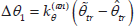
While a robot is performing various motions in an uncertain environment, it is often difficult to determine an appropriate and instantaneous desired angle,
2.2. Measure of posture stability using FSR
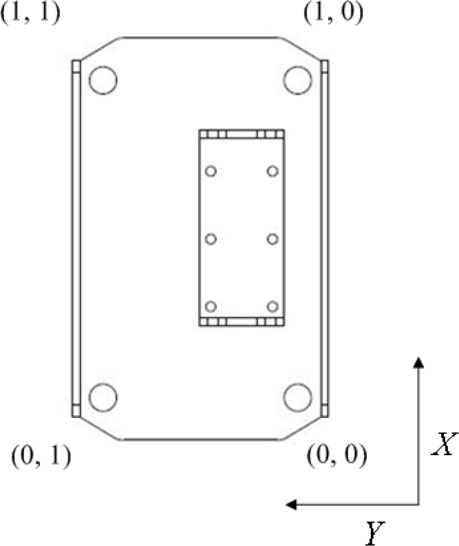
Inside the sole area of the supporting foot, the FSR installed in ROBOTIS-OP maps the current pressure point on which the whole body exerts its weight. The commercial FSR module produces a two-dimensional integer coordinate of ZMP ranging from 0 to 254 in the asymmetric coordinate frame as shown in Fig. 2. Therefore, the raw FSR data is transformed from integer values to real numbers between 0 and 1, which is called normalized ZMP (NZMP) by the following relationship:

Local FSR coordinate frames of each foot

where left(right)_fsr_x(y) represent the FSR data acquired from the left (right) foot in the local x-axis (y-axis), respectively, as defined in Fig. 2.
Figure 3 shows the resultant two-dimensional
Global normalized ZMP coordinate frame of both feet transformed from the local FSR coordinate frame
As a stability measure, the distance of the actual ZMP from the nearest boundary of a desired stable region (DSR) is proposed in the conventional SRC as shown in Fig. 4 [8]. If a ZMP of the current posture is located inside the DSR, the posture is regarded as stable. However, if it begins to escape out of the DSR, the stability is considered proportionally weakened. The distance of the current ZMP,

Desired stable region in the sole of the support foot
In the present paper,
3. Pattern Generation of Stable Walking
3.1. Humanoid robot model
The Denavit-Hartenberg (DH) convention is the standard method for the kinematic modelling of robots [11]. However, it is difficult to solve inverse kinematics with the DH method because of the numerical instability occurring at the inversion of
In the present work, a humanoid robot has a total of 20 DOFs including 11 pitch joints with variables from θ1 to

3D Stick diagram of the humanoid robot viewed from the sagittal plane and the coronal plane
3.2. Optimization of the biped walking pattern
To ensure reliable biped walking, the walking pattern should be deliberately designed, which satisfies the constraints of dynamic stability. Huang et al. [8] generated a dynamic walking pattern based on the ankle angle constraints of the swing foot and smooth hip trajectory with the largest stability margin using third-order spline interpolation. However, they only dealt with lower body joints rotating in the two-dimensional sagittal plane, which is not realistically implemented in an actual robot. The roll joints of the ankle and hip play a key part in sustaining the whole body in a single support phase, thus stabilizing angular trajectories for the roll joints should be included in the walking effort. In addition, the swing foot trajectory needs to be high enough to avoid obstacles in case of encountering rough terrain.
In [10], the optimal biped walking pattern is automatically generated using a global optimization method called particle swarm optimization (PSO) [13], which produces optimal variables that satisfy the four constraints: knee/ankle limitation, positive swing foot height, the tracking reference ZMP trajectory, and the following reference swing foot trajectory. The reference ZMP trajectory for a periodic step is depicted with a piecewise linear function as shown in Fig. 6, where the white rectangle represents the left supporting foot and the grey ones denote the movement of the right swing foot.

Reference ZMP trajectory for a periodic step [10]
The equation of the linear function for the reference ZMP position
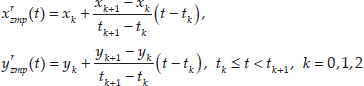
where the triplet
The reference swing foot trajectory used in the fourth optimized walking constraint is depicted with a three-segment blending polynomial as shown in Fig. 7, which is similar to a human's swing foot profile. A blending polynomial is produced by attaching multiple trajectory segments—expressed with a low order polynomial function such as cubic spline—and specifying each segment by its terminal via points [3]. Applying the condition of continuity in the function value and the derivative at each via point, the shape of the overall trajectory becomes sufficiently smooth for use in the joint angle trajectory of a humanoid robot.
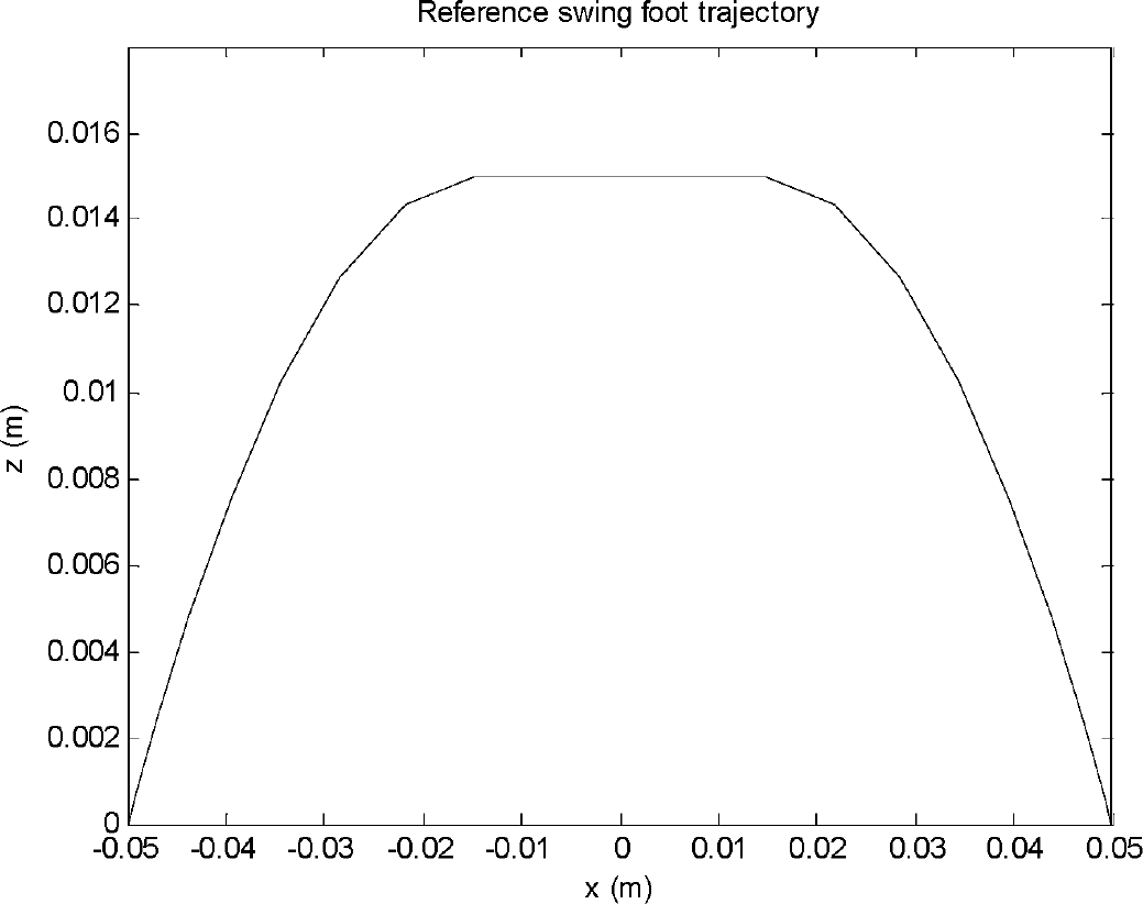
Reference position trajectory of the swing foot during the walking phase
The overall cost function for stable biped walking is described with the following equation:

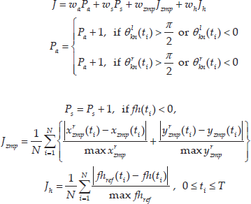
where
Figure 8 shows the Matlab simulation of the optimal walking method for the left support attained after performing PSO and Figure 9 displays the reference and optimized trajectories of the ZMP and swing foot position. The advantage of this approach is that one can shape a desired trajectory by simply changing some parameters of the blending polynomial.

Matlab simulation of optimal biped walking in left support

A comparison of the reference and optimized trajectories of ZMP and swing foot position attained by PSO
4. Sensory Reflex Control
4.1. Sensory reflex control based on ZMP
In the present paper, the ankle, knee, and hip joints in the sagittal plane are controlled with ZSRC, considering the effect of each joint on posture stability.
For the ZSRC of the ankle joint, maximum and minimum limit angles are temporarily set from the current ankle joint angle when the measured ZMP escapes from the frontal boundary or the rear boundary of the DSR respectively. This is due to the fact that
The rule of setting maximum and minimum limits on the ankle angle derives from the definition of rotation shown in Fig. 5, where the left and right ankle pitch angles,

where
Unlike Huang et al. [8], this paper additionally proposes a posture stabilization scheme for knee and hip joints that employs ZSRC. To compensate the knee joint in the supporting leg, a mathematical relationship between the change of knee joint angle,

where
Replacing θ2 and X2 with

When the robot is tilting forward

Substituting (8) with the term in (7) and rewriting it leads to the following equation:

where
The third strategy of ZSRC is to let the hip joint in the support leg rotate adequately to resume the erect trunk quickly. The trunk pitch angle
As the robot tilts forwards,

where
In this paper ZSRC is not applied to control of the roll ankle and hip joints in the support leg because of the high sensitivity of FSR outputs in the Y direction.
4.2. Sensory reflex control based on trunk angle
When a humanoid robot walks on an uneven and/or inclined floor, FSR often fails to provide precise information on the current posture stability. In this case, the inclination angle of the trunk is a good resource to indicate the stability of the robot. Fig. 10 illustrates the moments when a humanoid robot is on the verge of falling back and to the left supported by the edge of the foot. In both cases, the absolute angles of the supporting foot deviating from the ground are α and β respectively.

Situations of standing on the edge of a single foot
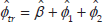
In case of Fig. 10(a), the X-axis NZMP reaches its lower boundary of 0 and thus an urgent control scheme for the ankle joint is necessary to prevent the robot from falling. Including the pitch deviation angle of the support foot from the ground, α, the actual pitch angle of trunk has the following relationship:

where
Let

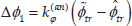
From observing (12), the output of SRC for the ankle pitch joint is described as:
where
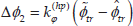
In the same manner, the hip pitch joint can contribute to quickly restoring the trunk to an upright position by replacing

where
In the case of Fig. 10(b), the robot is prone to falling to the left, and thus the ankle roll joint must rotate in a anticlockwise direction to restore the trunk angle to an upright position. Including the roll deviation angle of the supporting foot from the ground, β, the actual roll angle relationship of trunk is described as
where
Let
where
5. Experiment Results
5.1. Pitch swing control
A majority of tasks assigned to humanoid robots will be serving people with repeated standing and stooping postures. As the robot lowers its trunk, the ZMP will move forward, weakening the posture stability. To this end, the ZSRC described in Section 4.1 is applied to the whole-body pitch swing motion while standing, which is commanded by rotating both ankle joints in a sinusoidal waveform of magnitude 10°.
Fig. 11 shows the average NZMP profiles when the robot performs sinusoidal swinging in a standing position. Since the humanoid robot stands on one leg or on both, the NZMP needs to be averaged in case of a double support phase. As shown in the figure, without the ZSRC for the pitch ankle, knee, and hip joints, the NZMP stays momentarily at the extreme boundaries of 0 and 1, when the robot is ready to fall down. However, the NZMP trajectory attained from the result of ZSRC is detached from the upper bound and shortly stays at the lower bound instead.

Average NZMP trajectories with and without ZSRC when the humanoid robot swings back and forth within ±10° while in a standing position
Fig. 12 displays the trajectories of the trunk pitch angle, where the trunk swings more than ±20° without ZSRC but less than ±10° with ZSRC. Fig. 13 shows the three pitch angle trajectories during the experiment. It is worth noting in the case of ZSRC that the resultant pitch ankle joint rotates inside the upper and lower boundaries determined by the measure of ZMP stability.
Trunk pitch angle profiles with and without ZSRC

Pitch angular trajectories with and without ZSRC for the ankle, knee, and hip joints in the left leg while the robot swings back and forth in a standing position
It is apparent from the experiment's results that the proposed ZSRC is quite effective in posture stabilization of the robot for the excessive pitch swing motion in a standing position.
5.2. Walking control
Since most floors of buildings and offices have slight inclinations, walking on an inclined floor is significant for the high mobility of humanoid robots. In this paper, ISRC is applied to the walking experiment of a humanoid robot on the floor with an angle of 7°.
Fig. 14 shows photos of a walking experiment carried out by ROBOTIS-OP on an inclined wooden plate. It walked two steps with a step length of 5cm. Despite low friction between the feet and the board, it can walk up it stably by virtue of ISRC. However, the humanoid robot without ISRC fails to walk on the floor because the gravitational force causing backward rotation of the robot has not been compensated for in this case.

Photos of ROBOTIS-OP's two-step walking on an inclined floor
Figs. 15 to 17 plot sensory data for NZMP, the trunk pitch angle, and the ankle pitch angle for the comprehension of the robot's status. Fig. 15 plots measured NZMP profiles with and without ISRC during the experiment. It is apparent in the figure that NZMP with ISRC tend to stay near to the centre position longer than without ISRC, which retreats to 0 because of the inclination of the floor. This aspect of NZMP implies that the ISRC enables the humanoid robot to walk with enhanced posture stability.

NZMP trajectories with and without ISRC when the humanoid robot walks up a sloped floor

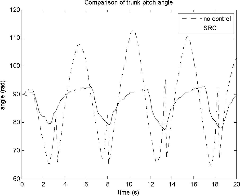
Profiles of the trunk pitch angle with and without ISRC
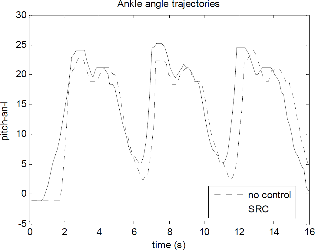
Profiles of the ankle pitch angle with and without ISRC
Fig. 16 compares the trunk pitch angle profiles for the two types of walking. Without ISRC, the gait pattern optimally generated for normal flat ground makes the trunk angle rotate more than an upright angle, which definitely leads to a fall backwards. Figure 17 magnifies the trajectories of the ankle joint angle with and without control, where the ankle joint rotates more in the case of ISRC to adjust the trunk angle upright from the ground.
All the experiments were carried out using only FSR and IMU sensors installed in ROBOTIS-OP and the experiment's results validate the effectiveness of the proposed ISRC for walking on a slightly sloped floor, which is impossible without the compensation of pitch joint angles.
6. Conclusion
This paper proposes an effective ZMP-based sensory reflex control scheme for balancing a humanoid robot statically moving in a standing position and an inclination-based SRC scheme for biped walking on a slightly inclined floor. In regards to ZSRC the ankle pitch joint is controlled to rotate inside the limit angles set online so the current ZMP does not flow out of the desired stable region, and the knee and hip joints help the humanoid robot quickly resume an erect trunk angle.
In the case that ZSRC is not available in the walking phase, the second control scheme, ISRC, is applied to adjust the pitch and roll angles of the ankle and hip joints in proportion with the measured trunk angle. The effectiveness of the proposed SRCs has been validated through experiments with a small humanoid robot ROBOTIS-OP.
Footnotes
7. Acknowledgements
This research was supported by the MSIP (Ministry of Science, ICT and Future Planning), Korea, under the ITRC (Information Technology Research Center) support program (IITP-2016-H8501-16-1017) supervised by the IITP (Institute for Information & communications Technology Promotion), and partly by the Human Resources Development of the Korea Institute of Energy Technology Evaluation and Planning (KETEP) grant funded by the Korea government Ministry of Knowledge Economy (No. 20154030200030).