
Abstract
This paper presents a novel solution for the classical leader-follower formation problem considering the case of nonholonomic mobile robots. A formation control strategy is proposed in a discrete-time context by considering the exact discrete-time discretization of the non-linear continuous-time kinematic model of the vehicle. The geometric formation of the robots allows us to derive an alternative model that describes the time evolution of the relative distance and angle between the robots. These variables are obtained in real-time by a vision-based localization system on board, in which the follower robot is equipped with a Kinect device, together with a recognition board mounted on the leader robot. The boundedness of the relative position error is formally proven by considering a feedback law that is delayed by one sampling period of time. Numerical simulations and real-time experiments are presented to verify the performance of the control strategy.
1. Introduction
The formation and cooperation of mobile robots are found in different fields: for example, in the aerial environment for navigation, exploration tasks, recognition of hostile terrain, aerial photography, terrain mapping or in the search and capture of ground targets [1, 2]. They are also considered for tracking and obstacle avoidance, patrolling an environment to prevent intruders in arbitrary topologies, 3D mapping, archaeological exploration and terrain recognition [3, 4]. In general, in order to perform such tasks, it is necessary to have a measuring device on board as in [5], where encoders and a compass on board are used to maintain the formation. In some cases, multiple devices are required to accomplish recognition of the environment: usually a laser system or a video camera [6, 7]. A special case is the detection of a leader robot or a particular pattern mounted on the robot [8].
The leader-follower formation problem has been analysed by considering several control strategies, mainly by means of the feedback linearization approach [9–13]. In [9], an on-board camera is used to estimate the orientation and the distance between the robots, and in [11], three different controllers are proposed and a camera is used for measuring the distance and angles between the vehicles, verifying the controller's performance by numerical simulation. Lyapunov-based control strategies have also been considered; for instance, in [14], two different controls are proposed using a camera fixed to the ceiling, while in [5, 15], the strategy is complemented by a receding horizon approach together with a single camera mounted on the ceiling. In addition, backstepping strategies have been implemented in the solution of the leader-follower problem; for example, in [16], the leader-follower formation is assured using Cartesian coordinates to avoid singularities that appear in polar coordinates. Backstepping and cascade system theory is used in [17] to control multiple robots and in [18], the method is complemented by a bioinspired dynamic to avoid impractical velocity jumps. The backstepping is merged with a fuzzy control strategy in [19] to perform an obstacle avoidance strategy. Game theory is used in [4] for terrain patrolling tasks, modelling the problem as a set of two players developing an optimal strategy for the solution of the problem. In [20], the leader-follower formation is analysed by measuring the relative distance between the vehicles from a mobile frame located on the follower robot, which is allowed to adopt a variable position under an input-constraints strategy.
One important aspect of the problem is the real-time implementation of the mentioned solutions. In this sense, there are two main approaches. The first one is based on a camera mounted on the ceiling of the working space as in [5] or [15], and the more general approach that considers an on-board camera used to estimate the orientation and the distance between the robots as in [9] and [21], in which observer-based solutions are proposed. In [22], the solution is based on an entropy segmentation that provides the relative-position estimation of the robots.
The objective of this paper is to analyse the leader-follower formation problem using a discrete-time approach: an approach that has not been considered in the literature. The consideration of a discrete-time strategy is based on the necessity of a practical implementation of the solution of the leader-follower problem stated in this work, which should be carried out, in general, by means of microprocessors or computer-based platforms. In addition, the discrete-time nature of the vision system seems to be more suitable for the approach proposed. In particular, a leader-follower formation based on relative distances between the robots is suitable for outdoor environments where an absolute localization system is difficult to implement. An exact discretization strategy based on direct integration, such as the one used in [23], is considered here.
The control of nonholonomic mobile robots of the type considered in this work is a challenging problem due to the fact that they do not satisfy the well-known Brocket's rank condition [24], which prevents the existence of a smooth time-invariant feedback for the solution of the stabilization problem. This problem is related to the control of the vehicle's posture. The standard formation problem is addressed in a discrete-time context assuming that the leader robot follows a free trajectory; it is intended that the follower robot tracks the leader within a specified distance using only a camera on board as a sensor. In this form, the solution does not depend on positions and velocities measurements, and only considers relative measurements between vehicles. To solve this problem, and following [16], a coordinate transformation is considered in which the relative time evolution of the position and angle between the robots is used.
Instead of a standard video camera, a Kinect device is used to estimate the relative distance and the angle between the leader and the follower robot. The solution of the problem is based on a non-standard discrete-time feedback that is retarded by one sampling period of time, which produces a closed-loop perturbed system. It is formally proven that the follower tracks the leader by using bounded tracking errors. The proposed formation strategy is evaluated by numerical simulation as well as real-time experiments by means of two differentially driven mobile robots.
The rest of the work is organized as follows. Section 2 describes the discretization procedure and the mathematical preliminaries that are used throughout the document. In Section 3, the leader-follower formation problem is geometrically stated and the control objective based on the relative errors is described. In Section 4, the solution to the leader-follower formation problem (the formation-error analysis and the main procedure to obtain the control law) is shown. The numerical and experimental evaluation of the proposed formation strategy is described in Section 5 and some conclusions are given in Section 6.
2. Discrete-time Model of the Mobile Robots
A differentially driven mobile robot (type (2.0)), such as the one depicted in Figure 1, is considered. The kinematic model of this robot is given by [25],
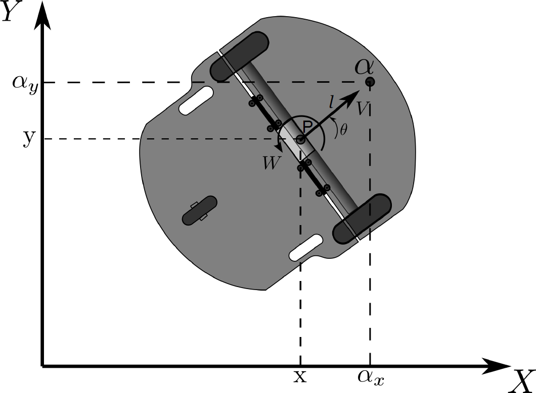
Representation of a mobile robot (2,0) in the plane

where x and y are the positions along the axes X and Y, respectively, and θ corresponds to the orientation angle of the vehicle. V and W are the linear and angular velocities of the robot.
The kinematic evolution of the point α, located at the front of the robot along the longitudinal axis, can be described by considering the changes to the following coordinates,

where

The linear and angular velocities of each robot are related to the angular velocity of the right wheel, wr, and the angular velocity of the left wheel, wl, by means of the relation,

where r is the wheel ratio and
The control of nonholonomic mobile robots of the type considered in this work is a challenging problem due to the fact that they do not satisfy the well-known Brocket's rank condition [24], which prevents the existence of a smooth time-invariant feedback for the solution of the stabilization problem. The use of Lyapunov techniques has provided solutions for a single robot by means of discontinuous feedback [26] or by means of time-varying control laws [27, 28]. Instead of considering the posture of the vehicle, in this work, controlling the Cartesian coordinates of the point α was preferred, while obtaining simultaneously the boundedness of the orientation angle.
2.1. Exact discrete-time representation
Taking into account the discrete-time nature of a real time implementation, an exact discrete-time representation of the kinematic equations (3) is considered. The non-linear kinematic model (3) can be discretized in an exact manner by considering a sampling period
Following [23], the time integration of the dynamics (3), with the initial condition evaluated at

where
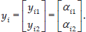
In addition to (5), the following output signals are considered:
Model (5)–(6) is used in the sequel to study a leader-follower formation problem.
3. Leader-follower Formation Problem
The configuration of a leader-follower formation is shown in Figure 2. The complexity of this formation is due to the difficulty of measuring the different relative positions and velocities that exist between the leader and the follower robot. The problem can be stated as follows.

Representation of the leader-follower formation of mobile robots type (2,0) in the plane

From Figure 2, it is possible to obtain the geometrical relationship between the leader and the follower robot. Note first that the distance l0 between the points

It is clear that the control objective (7) can be rewritten in terms of the evolution of lx and ly. That is, it is required that,
The time evolution of lx and ly can be obtained by considering a direct forward shift of equation (8), this is:


Substituting
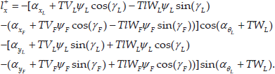
After a number of manipulations and substitutions of some trigonometric identities, one finds that the dynamics of lx can be written as:

where the orientation error between the vehicles eθ, is defined as
Considering equation (8), it is possible to rewrite equation (11) in the form:
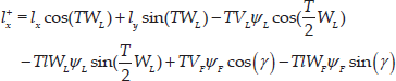
where
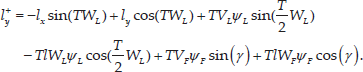
Applying a similar procedure to
The leader-follower formation problem can be alternatively described in terms of relative position errors, defined as

for a desired time-varying angle
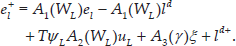
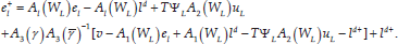
The time evolution of

which can be rewritten in the form:

Following a similar procedure for

4. Delayed Feedback Solution to the Leader-follower Problem
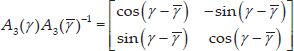
According to the definition of the leader-follower problem as stated in Section 3, the follower robot must be able to follow any path described by the leader robot while maintaining a constant distance with respect to it. Therefore, the design of the control strategy should be based on the follower's control signals VF, WF. In order to simplify the developments of the required feedback, equations (15) and (16) can be rewritten in the compact form:

where,

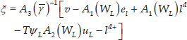
To obtain a solution to the leader-follower problem, the virtual control signals,
A feedback law can now be synthesized based on the virtual controls ξ as:
where the new input signal v is selected as:

where
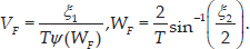
The original control signals VF, WF can be derived from ξ1 and ξ2, more precisely:
Let us now consider the formation error dynamics (18), together with the feedback (19); this is:
Note first that,
where

where

with

where

It is possible to show that the terms h1 and h2 are appropriated bounded functions. The term h1 can be majored as:

Then, due to the boundedness of matrices Δ, K and

The term h2 can be majored as:

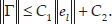
Since

for a non-zero positive constant C2. Hence, from (26) and (27), it is obtained that:
4.1. Formation error analysis
Based on the previous developments, it is now possible to state the main result on the evolution of the formation error, as follows.

is satisfied, then the formation error
Proof. The time evolution of the closed-loop formation error e can be determined by considering the solution of equation (24); this is:
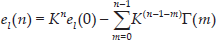
which can be majored by using bound (28) as follows:

Since the eigenvalues of the matrix K are all within the unit circle, one finds that:

Therefore, from equation (31), the ultimate bound can be obtained as:

Then, if condition (29) holds, the formation error
The result stated in Lemma 4 assures the boundedness of the formation error but it cannot determine the evolution of the orientation of the follower robot. This is an important issue since the control of the follower vehicle is carried out by considering the point

Since WL is an input to the leader robot that generates the tracking trajectory, it can be assumed to be bounded. Also, from (21) it is clear that WF is also a bounded function. Therefore, the evolution of the formation error is bounded. The evolution of

Then, by considering the last equation in (5) and the definition of γF, one obtains:
Equation (34) is the discrete-time counterpart of the continuous time nonholonomic restriction:

associated with the original system (3). The importance of equation (34) is that since the proposed leader-follower control strategy determines the evolution of the point
5. Experimental Evaluation
The solution proposed for the leader-follower formation problem (21) is initially evaluated by numerical simulations and by real-time experiments carried out using a pair of differentially driven wheeled mobile robots of the type Pioneer 3-DX from MobileRobots Inc.
5.1. Numerical results
A numerical experiment (NE) was carried out by considering that the leader robot follows a circular path with a radius of
Figure 3 depicts the evolution of the leader-follower formation on the Cartesian plane. It can be observed that the trajectory tracked by the follower robot is different from the one developed by the leader robot. This is a consequence of the control strategy that considers the control of the relative distance between the robots and not a specific path.

NE. Time formation evolution on the Cartesian plane.
The tracking errors

NE. Cartesian relative errors
5.2. Experimental platform
As mentioned above, two differentially driven mobile robots of the type Pioneer 3-DX that support loads of up to
Relative distance and orientation recognition using the graphical pattern and Kinect device
5.2.1. Vision-based localization system
This section provides an overview of the major steps of our method for detecting the leader robot from the visual information provided by the Kinect device that is on-board the follower robot for feedback purposes. The Microsoft Kinect device contains a depth sensor, an RGB camera and a four-microphone array. The Kinect device has the capabilities to perform 3D motion capture, and face and voice recognition [29]. The depth sensor consists of an infrared projector to differentiate depth by infrared vision. The infrared projector and a monochrome CMOS sensor in the Kinect device is combined to capture video data in 3D under any ambient light conditions. The vision sensor provides a maximum of 30 frames per second with a resolution of
The Kinect depth sensor can detect the distance of an object so that an autonomous robot can navigate while avoiding obstacles in an indoor environment [30]. The three-dimensional space is reconstructed by merging the two images obtained by the RGB and the depth camera. The RGB camera obtains the image of the environment while the depth camera obtains the depth information of each pixel in the image. A detailed analysis of the accuracy and resolution of the Kinect can be found in [31].
Before its use, the Kinect has to be calibrated to merge the data of the images obtained by the cameras and to process the raw data of the depth sensor. This calibration was done as in [32], following the procedure developed in [33]. The depth information obtained is linearly perpendicular to the longitudinal axis sensor. Thus, all the objects that are over the same line will have the same depth value, regardless of whether they are at the edge or at the centre of the image; this distance is denoted as
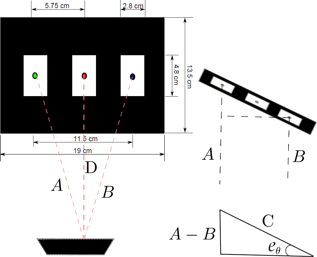
Figure 5 shows how the distance between the centre of the image and a centroid of the recognition pattern board is calculated; first by obtaining the depth information of the central point of the image and then by determining the number of pixels that exist between these two points at the same depth. The distance covered by each pixel is obtained experimentally using the approximate relation

Distances between the centre of the image to the centroid of the recognition pattern
Knowing the number of pixels
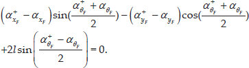
Figure 6 shows how the recognition pattern on the leader robot is used to obtain the orientation error eθ. Once the distance of the three centroids are determined from the Kinect information, the distances A and B (see Figure 6) are used to compute the relative orientation angle, eθ, between the robots. This error is calculated using basic trigonometry; since the distance between the external centroids on the graphical pattern (
From the geometric relation between the robots, as shown in Figure 7, it is clear that the relative distances lx, ly used to obtain the solution to the formation problem can be obtained as:

Geometrical representation of the alpha point and the middle point of each robot
5.3. Real-time results
Two real-time experiments were carried out in order to evaluate the proposed solution. The first one considered the tracking of a straight path by the leader robot, and a sinusoidal path for the second experiment. In both cases, the follower robot must track the leader vehicle at a constant distance of one metre
5.3.1. Straight path experiment (StPE)
Even when, in the presented solution to the problem, internal or external disturbances have not been considered, a disturbance was introduced on the straight path experiment as a practical evaluation of the robustness of the discrete-time strategy. At approximately
The evolution of the relative errors
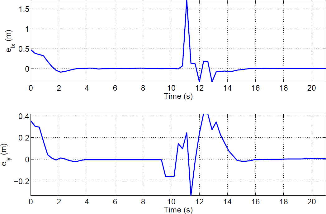
StPE. Behaviour of the relative errors

StPE. Evolution of the non-controlled error eθ.

StPE. Control signals VF, WF.
Note that the effects of the external disturbance are more evident in Figure 9, where eθ becomes an unbounded signal and, because of the physical characteristics of the experiment, this signal should have a magnitude between
5.3.2. Sinusoidal path experiment (SiPE)
The sinusoidal path described by the leader robot was obtained by considering:
The relative errors

SiPE. Behaviour of the errors

SiPE. Evolution of the non-controlled error eθ.

SiPE. Control signals VF, WF.
Finally, the disturbance terms

SiPE. Perturbation signals evolution
6. Conclusions
The leader-follower formation problem for nonholonomic differentially driven mobile robots is addressed in this work by considering the discrete-time representation of the kinematic models of the robots. To deal with the associated kinematics constraints, a control located at the front of the robot is considered. A solution to the problem is obtained by considering a single sampling time delayed feedback, based on relative distances and angles between the robots that are measured by an on-board camera mounted on the follower robot, together with a graphical pattern mounted on the leader robot.
It is formally proven that the relative Cartesian errors with respect to a desired relative distance between the robots are ultimately bounded. The main advantage of the proposed discrete-time strategy lies in its ease of implementation on microprocessors or computer-based platforms, and the consideration of the vision system that is of a discrete nature. The main disadvantage of the solution proposed is the closed-loop practical stability property of the convergence errors, since they converge to the origin only for constant angular velocities. The proposed strategy was evaluated via numerical and real-time experiments in a laboratory environment, using a low-cost measurement device. The use of relative distances between the leader and the follower robot has been previously used in the literature in a continuous time context; it is shown in this work that a discrete-time approach can also be exploited in the solution to the problem.
Footnotes
7. Acknowledgements
Part of the work of M. Velasco-Villa was done while on a sabbatical supported by Conacyt-México (No. 260936) at the SEPI of the ESIME-Culhuacan IPN.