
Abstract
This paper introduces a novel thruster fault diagnosis and accommodation system for open-frame underwater vehicles with abrupt faults. The proposed system consists of two subsystems: a fault diagnosis subsystem and a fault accommodation sub-system. In the fault diagnosis subsystem a ICMAC(Improved Credit Assignment Cerebellar Model Articulation Controllers) neural network is used to realize the on-line fault identification and the weighting matrix computation. The fault accommodation subsystem uses a control algorithm based on weighted pseudo-inverse to find the solution of the control allocation problem. To illustrate the proposed method effective, simulation example, under multi-uncertain abrupt faults, is given in the paper.
Introduction
Thrusters of UV(underwater vehicles) are one of the most common and most important sources of faults, and its faults always make direct effect in the control performance, therefore FTC(fault-tolerant control) for thruster of UV is a research hot topic nowadays (Gianluca, A., 2006). Some results of FTC about UV had been reported in recent ten years. A fault-tolerant system for use in an experimental AUV (Autonomous Underwater Vehicle) was outlined by Yoerger, Yang, Yuh, and Choi (Yoerger, D. & Slotine, E., 1991; Yang, K. & Yuh, J., 1998; Yang, C. & Choi. K., 1999). The system was subdivided into individual fault tolerant subsystems for dealing with thruster and sensor failures separately. The thruster subsystem consisted of a rule base for detection and isolation purposes, and a control law reconstruction algorithm was realized by eliminating the corresponding column. But only a whole (total) fault of the thruster was considered in these researches, and scope of actual applications and control effects of FTC are poor.
In order to improve control performance, the problem of optimal distribution of propulsion forces for over actuated UV is addressed in (Podder, K. & Sarkar, N., 1999; Podder, K. & Antonelli, G., 2000; Podder, K. & Sarkar, N., 2001) by Podder T.K. after 2000. The authors investigate how to exploit the excess number of thrusters to accommodate thruster faults. This approach resolves the thruster redundancy in the Cartesian space and allows the AUV to track the task space trajectories with asymptotic reduction of the task space errors. But only the whole(total) fault of the thruster was still considered, that was different from the actual fault situations of the thrusters.
In recent years, the method based on the SOM(self-organizing maps) was proposed in (Cuadrado, A. & Diaz, I.; Edin, O. & Geoff, R., 2004). The fault accommodation subsystem used weighted pseudo-inverse to find the solution of the control allocation problem (Fossen, T., 1995; Tondel, P., 2003). Two approximations (truncation or scaling) can be used to ensure feasibility of the solution. In the case of a partial fault, the thruster is typically allowed to continue operation with the restricted factor s ∈ (0, 1]. The numerical value of s depends on the type of the fault. Normal state and three different fault cases are considered(jammed, heavy jammed and broken propeller) in literature(Edin, O. & Geoff, R., 2004). However, in actual applications of UV, the degree of jammed is continuous and uncertain. So a new on-line identification algorithm which is much more closer to the actual condition is urgently needed to be designed.
This paper focuses on multi-uncertain abrupt time-variant faults situation, a novel approach to fault diagnosis and fault-tolerant control of thruster for a class of open-frame unmanned underwater vehicles is presented. In this approach, ICMAC neural network(Zhu, Q. & Kong, M., 2006; Zhu, Q. & Kong, M., 2007) is used to realize the on-line fault identification. The fault accommodation unit uses information of the fault provided by the neural network to accommodate fault and perform an appropriate control reallocation.
This paper is organized as follows in the second section, the basic control architecture, thruster configuration and force allocation are introduced. In the third section, fault diagnosis subsystem and fault accommodation subsystem is presented separately. To illustrate the proposed method, a simulation example, is given in the fourth section. Finally, some concluding remarks are made in the fifth section.
Thruster configuration
Control architecture
The UV (FALCON, seen Fig.1.) (Edin, O. & Geoff, R., 2004) are used to demonstrate the performance of the fault diagnosis and fault-tolerant system. This ROV has no other actuators except fixed direction thrusters, and the following discussion will be concentrated on this type of actuators, while more information about other types can be found in (Johansen, A. & Fossen, I., 2004; Fossen, I., 2002). It has four horizontal thrusters, denoted as i HT, i ∈[1, 4] and one vertical 1VT (not shown in Fig.1-bottom). Thruster configuration of the FALCON enables direct control of 4 DOF (Degree Of Freedom): surge, sway, yaw and heave.
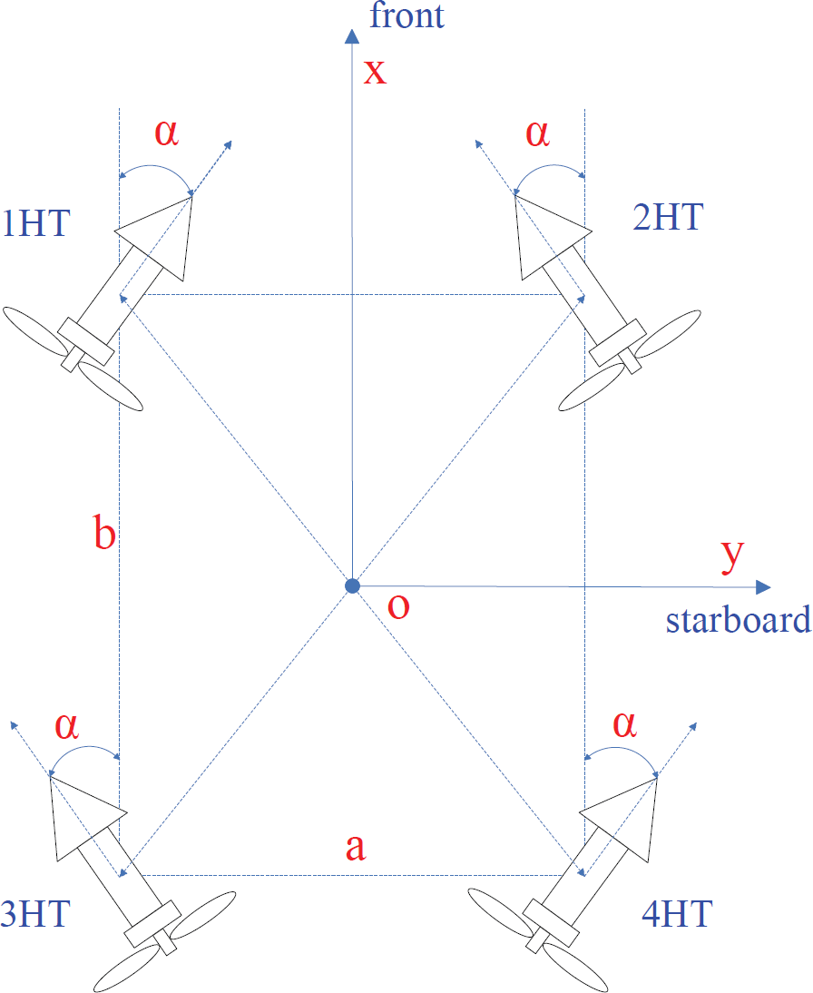
configurations of the horizontal thruster
Vector τ
d
can be decomposed into two parts as
In the paper only the horizontal plane motion control is discussed. Each thruster exerts thrust (force)

Where K is the motor control parameter, superposition of the A = (b/2)sin α + (a/2)cos α leads to total vector of propulsion forces and moments τ in the horizontal plane:

Where τ = [τ
X
τ
Y
τ
N
]T are represented as the motion of surge, sway and yaw respectively. Each component of the control vector is limited by constraint:

Where u
m
is the thruster maximum control velocity, from (1) and (2):


Constraint (3) represents thruster velocity saturation, because the thruster cannot rotate faster than its maximum velocity. So from(4) (5) (6), expression (2) can be rewritten in the normalized form (7), detailed can be seen in literature (Podder, K. & Antonelli, G.).
In (7), τ
m
= [τ
Xm
τ
Ym
τ
Nm
]
T
are represented as maximum values of the surge and sway forces and the yaw moment. Finally, the general constrained control allocation problem for open-frame UV can be formulated as: For given normalized

For formula(7), when the thruster fault-free, the motor control voltage u will produce the corresponding rotational speed n, and get the corresponding propulsion forces and moments τ; But at thruster fault situation, with the same motor control voltage u, the thruster can not produce the same rotational speed n, and do not get the corresponding propulsion forces and moments

Where formula (8)
In the paper formula (8) can be used to calculate the propulsion forces and moments
In the control system of UV with multi-thruster, a weighting matrix is designed and can be used to decide which thruster should be used primarily. The weighting matrix W
HT
(in the horizontal plane) is chosen to be a diagonal matrix:

In the fault-free case, all horizontal thrusters have the same priority and W
HT
is chosen to be equal to identity matrix. In the case of a partial fault, the thruster is typically allowed to continue operation with the new restricted usage:

The restricted factor value S
i
is 0 ≤ s
i
< 1, and depends on the fault value. s
i
= 1, which means that thruster has non-fault; When s
i
→ 0 means thruster has total fault, and completely ineffective; When 0 ≤ s
i
< 1, means that thruster has partial fault. s
i
can be calculated by (11):

Where n is normal shaft speed of the thruster, f
i
is the fault level which is the output of the neural network. In this paper an ICMAC neural network is used to realize the on-line fault identification. In addition to the change of the constraint bounds, the weight

Where:

The weight update (12) is introduced to penalise the faulty thruster, prioritise healthy thrusters and to compensate restricted usage of the faulty thruster in an optimal way.
Fault diagnosis subsystem
Thruster fault patterns are classified into two classes (Omerdic, E &Roberts, N), ①Internal faults (e.g. temperature of the winding is out of range, lose communication, drop in bus voltage, etc.), ②External faults (e.g. jammed or broken propeller). In two classes thruster faults, external faults is main and common. Thrusters usually work under the formidable circumstance. A thruster fault can occur due to various reasons. Some of these faults (partial faults) are not critical and the thruster is able to continue operation in the presence of a fault with the restricted usage. In literature (Edin, O. & Geoff, R., 2004) the restricted constraint bound s i is discrete. Only normal state and three different fault cases were considered (jammed, heavy jammed and broken propeller), however, in actual applications the number of faulty cases can be very much, and it is continuous change and uncertain. it is not suitable to regard the jammed fault f i as several fault states. In the paper the ICMAC neural networks (Zhu, Q. & Kong, M., 2006; Zhu, Q. & Kong, M., 2007) is used to online identify the jammed degree of the thrusters.
The basic concept of CMAC is to store the learning data (knowledge) into overlapped storage hypercube (remembering space), and its output is the addition of data in addressed hypercube. Two kinds of operating are included in the conventional CMAC, one is calculating the output result and the other is the adjustment of weight (the corrected amounts of errors). In the conventional CMAC learning scheme, the corrected amounts of errors are equally distributed into all addressed hypercubes, regardless of the credibility of those hypercubes values. But the correcting errors should be distributed in accordance to the hypercubes reliability, the only available information about hypercubes reliability is the current weight updating times of the hypercube. The more the hypercnbe updates, the more reliable the stored data are. So the learning times of the hypercube is seen as credit index. The more times the addressed hypercube have learned, the higher the credit assignment is, and the less the weight will be adjusted. In the ICMAC the proposed improved learning approach is to use the learned times of the addressed hypercubes as the credibility values of hypercubes learned, the corrected amounts of errors are proportion to the inversion of the learned times of the addressed hypercubes. The learning accuracy of ICMAC is higher than conventional CMAC and the error descent is very quick. The detailed algorithm and results can be seen in (Zhu, Q. & Kong, M., 2006).
The Fig.2 is structure of the fault diagnosis subsystem. Control signals given by Fault Accommodation Unit, can be transferred to normal thruster model and actual faults thruster respectively. The output of the model is desired output in every step. Actual thruster is simulated by a DC motor control system model with unexpected fault, where fault is assumed to be unknown. During the normal state, the nominal control signal drives the behaviour. Once an abnormal system behavior is detected by the fault detection subsystem, an online estimator initially starts to learn the failure by using the difference between the desired output and actual output as the desired target of the ICMAC network, and after some steps of training the network will output the forecast value of fault, no matter what kind of fault (i.e. some state range between jammed and heavy jammed), and the control law is computed exactly and reconfigured by the fault accommodation subsystem based on the current knowledge of the failure dynamics provided by the online estimator.

the fault diagnosis subsystem
A standard ROV control structure is shown in Fig.3. The description of the architecture will be given in two subsystem: fault diagnosis subsystem and fault accommodation subsystem. The desired vector of propulsion forces and moments

ROV control structure
For given

Where

Simulation of fault diagnosis and fault-tolerant control
A large number of open-frame underwater vehicles use DC motor to drive the propeller. It is well known that a DC motor can be modeled as a linear time-invariant system (Lingli, N., 2001), the nominal transfer function can be represented by equation (16):

Where n(s), u(s) denote the rotational speed and motor voltage in s domain, respectively. K
b
, K
m
, R
a
, J and d are motor constants. Equation (16) can be reorganized as:

Using the forward Euler approximation, the discrete time nominal model can be derived and shown in equation(18):

Wheren(k + 1) and u(k) represent the system output and control input at the time step k+1 and k, respectively. In the paper f
linear
= 0.9, g
linear
= 02. Under two unexpected abrupt faults modes f
i
(k) = U(k-T) q
i
(k), the every thruster system is represented by the following equations:

Where two unexpected abrupt faults are generated at the first thruster and third thruster respectively,

Let desired
The control objective in this experiment is to maintain the
Fig.4. shows the actual rotational speed of the four thrusters and the fault-free speed within the steps 600. When the unknown abrupt faults happen at the first thruster at the step 200, the third thruster at the step 40 respectively. As seen, only the speed of the first and third thruster performance degrades at the time steps 200 and 40 respectively, and the rest of the thrusters are fault-free. Fig.5. shows output of the forces and moments and the magnitude error without the fault-tolerant control unit. We can see the system performance degrades from the

The actual speed vs. fault-free speed of the motor without the fault-tolerant control

The actual output vs. desired output without the FTC and magnitude error
The magnitude error is generated after the time steps 40, and it becomes more large after the time steps 200. It is because the unknown abrupt faults happen at the first thruster after the step 200, the third thruster after the step 40 respectively.
Fig. 6. shows the control voltage of all thrusters, we can see that all thrusters have been accommodated according to the faults, the first and third thrusters with fault are penalized by increasing its weight, in order to maintain the balance of the forces and moments, and the corresponding thrusters are all changed according to the weighting matrix.

The control voltage of the fault-tolerant control
Fig. 7. shows output of the forces and moments and the magnitude error with the fault-tolerant control unit. Clearly that the system performance is greatly improved. The fault accommodation subsystem successfully drives the output of the unknown faulty system back to the desired state:

The actual output vs. desired output with the FTC and magnitude error
In this paper, the online fault accommodation for open-frame underwater vehicles system is investigated. An efficient online fault diagnosis subsystem and fault accommodation subsystem are presented. The online fault diagnosis subsystem ICMAC greatly improves the performance of the on-line faults identification. With the algorithm based upon weighted pseudo-inverse, the error has been greatly reduced. The fault-tolerant control system successfully drives the system back to the desired state with the unknown abrupt faults.
Footnotes
6.
This project is supported by the National Natural Science Foundation of China. (50775136), the 863 High-technology Research and Development Program of China (2006AA09Z210) and the Natural Science Foundation of Shanghai (07ZR14045).