
Abstract
A more suitable motion planning method for an omni-directional mobile robot (OMR), an improved APF method (iAPF), is proposed in this paper by introducing the revolving factor into the artificial potential field (APF). Accordingly, the motion direction derived from traditional artificial potential field (tAPF) is regulated. The maximum velocity, maximum acceleration and energy consumption of the OMR moving in different directions are analyzed, based on the kinematic and dynamic constraints of an OMR, and the anisotropy of OMR is presented in this paper. Then the novel concept of an Anisotropic-Function is proposed to indicate the quality of motion in different directions, which can make a very favorable trade-off between time-optimality, stability and efficacy-optimality. In order to obtain the optimal motion, the path that the robot can take in order to avoid the obstacle safely and reach the goal in a shorter path is deduced. Finally, simulations and experiments are carried out to demonstrate that the motion resulting from the iAPF is high-speed, highly stable and highly efficient when compared to the tAPF.
Keywords
Introduction
With the special mechanism of omni-directional wheels, the OMR performs 3 degree-of-freedom (DOF) motion on the two-dimensional plane, which can achieve translation and rotation simultaneously along arbitrary direction. Due to the agile performance (Pin, F.G. & Killough, S.M. (1994)), OMRs have been popularly employed in many applications, especially in omni-directional wheelchairs (Wada, M. & Asada, H.H. (1999)), soccer player robots considered in RoboCup competitions (Samani, A. H. et al., (2004)), and millimeters size micro-robot (Li, Z.B. et al., (2006)).
Different from traditional mobile robots, the maximum velocity and acceleration (Wu, J. et al., (2006)), and motion efficacy of the OMR are different while it moves in a different direction, this is called anisotropy. Especially owing to the different applications, the arrangements of the omni-directional wheels are not generally symmetrical, which makes the anisotropy much more distinct. Accordingly, the motion planning of OMRs along different directions result in different trajectories and motion efficacy.
Motion planning is an important branch of mobile robot research, and collision-free path planning also plays an important role for OMR study. Many motion planning methods were proposed. Felipe et al. (Felipe, H. & Miguel, T. (2006)) analyzed and compared three path planning methods for omni-directional robots, which are based on the Bug algorithm, the Potential Fields algorithm and the A* algorithm. Suzuki et al. (Suzuki, T. & Shin, S. (2005)) used the descendent gradient of a navigation function to find a shorter and safer path for OMRs. To achieve a high-speed navigation, Brock et al. (Brock, O. & Khatib, O. (1999)) considered the agile performance of OMRs, and proposed a global dynamic window approach. Moore et al. (Moore, K.L. & Flann, N.S. (1999)) described a multi-resolution behavior generation strategy for a novel omni-directional autonomous robot, and the strategy is characterized by a hierarchical task decomposition approach. But due to the anisotropy of motion characteristics, the former motion planning applicable for traditional mobile robots is not suitable for OMRs. All of them considered the OMR as an isotropic problem and therefore the potential of OMRs were not fully exhibited.
There are also many papers on the trajectory control of OMRs, which have taken into consideration, the motion characteristics. Balkcom et al. (Balkcom, D.J. et al., (2006)) considered a kinematic model of the vehicle and placed independent bounds on the speeds of the wheels, and derived the fastest trajectories between configurations. Wang et al. (Wang, S.M. et al., (2007)) solved the time-optimal control problem as a constrained nonlinear programming (NLP) problem according to the kinematic model. Kalmar-Nagy et al. (Kalmar-Nagy, T. et al., (2004)) made use of the characteristics of OMRs to simplify the control problem, and presented an algorithm for a near-optimal dynamic trajectory generation with low computational cost. Koh et al. (Koh, K. C. & Cho, H. S. (1999)) considered the dynamic constraints for a smooth path tracking to avoid wheel slippage and mechanical damage based on “bang-bang” control. Wu et al. (Wu, J. et al., (2006)) proposed the novel concepts of Velocity and Acceleration Cones for determining the kinematic and dynamic constraints, and studied the motion planning of OMRs without obstacles. Wu (Wu, J. (2004)) presented the research about motion planning of OMRs in his Ph.D. dissertation. Using the ability of translation along arbitrary directions, a coordinating velocity in the vertical direction of motion was introduced to accommodate maneuvers for a safe route.
Due to its simplicity and mathematical elegance, APF is widely used for collision-free path planning. Originally the APF developed by Khatib (Khatib, O. (1986)) was used in a stationary environment. However, because environments are dynamic in most real-world implementations, APF has been improved to suit the extensive environments in the past decade. For examples, Luh et al. (Luh, G.C. & Liu, W.W. (2007)) proposed a potential field immune network. Also, an artificial coordinating field was introduced to APF by Jing et al. (Jing, X.J. et al., (2004)), i.e. a coordinating force was used for coordinating the APF. For an optimal control system, Shimoda et al. (Shimoda, S. et al., (2005)) considered the dynamic constraints and dynamic environments into APF. Guldner et al. (Guldner, J. & Utkin, V.I. (1995)) introduced a sliding mode control strategy for tracking the gradient of an artificial potential field, which obtained good results.
Although, APF has been studied for OMRs, for example, Ge et al. (Ge, S.S. & Cui, Y.J. (2002)) proposed a new APF method in dynamic environments where the goal and the objects are moving, and made a motion planning for OMR with the method. Samani et al. (Samani, A. H. et al., (2004)) described an omni-directional soccer robot system, in which APF was used for the trajectory planning. There have not been any APF that takes into consideration the characteristics of OMRs. And the anisotropy of OMRs was also not taken into account. Because the motion planning of OMR along different directions results in different trajectories and motion efficacy, to achieve a high-speed, highly stable and highly efficient navigation, it is necessary to improve the APF for the application to OMRs. Due to the agile performance and anisotropy, considering the effects of the dynamic environment, based on tAPF, the study on an improved motion planning algorithm which will result in a short-trajectory, high-speed, highly stable, highly efficient, collision-free path is the main objective of this paper.
Most work on motion planning for OMRs focused on the time-optimality, and there are few studies on the stability and the motion efficacy by analysis of kinematic and dynamic characteristics. For optimal motion planning, making a proper trade-off between time-optimality, stability and efficacy-optimality is very important. Therefore, a novel concept of an Anisotropic-Function based on the analysis of kinematics and dynamics of OMRs is proposed, which synthesizes the velocity, acceleration and motion efficacy. By regulating the weights of the Anisotropic-Function, we can obtain a proper trade-off between time-optimality, stability and efficacy-optimality. And the “Variable Motion Direction Area (VMDA)” for a collision-free path and shorter path are defined according to the information of the robot, obstacles and goal. Considering the characteristics of an OMR, we introduce the revolving factor into tAPF to coordinate the resultant force direction of APF. Finally, an improved motion planning method which can fully exhibit the advantages of OMRs is proposed. With the ability to translate along any arbitrary direction, the trajectory in this research is composed of a piecewise translation motion, i.e. the orientation of the robot will not change.
The improved motion planning algorithm based on Anisotropic-Function presented in this research was applied to the OMRs developed in our laboratory, with much better Obstacle avoidance and efficacy of capturing the target. Simulations and experiments were carried out and the results were promising.
The present paper is organized as follows: Section 2 presents the anisotropy of OMR, including kinematic analysis, dynamic analysis and motion efficacy analysis, and the novel concept of an Anisotropic-Function is proposed; Section 3 describes the “Variable Motion Direction Area”; based on the Anisotropic-Function, an improved APF is proposed in Section 4; Section 5 illustrates the effectiveness of the improved motion planning by performing simulations and experiments; finally, conclusions are drawn in Section 6.
Anisotropy analysis for OMRs
Kinematic Modeling and Maximum Velocity Analysis
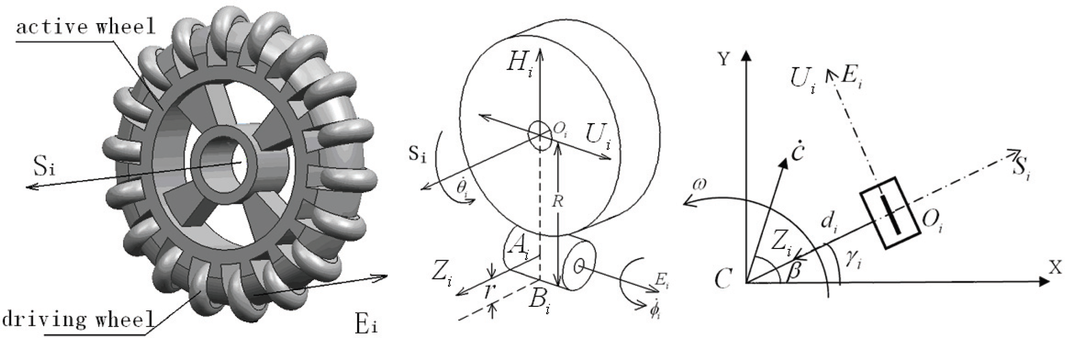
There are many kinds of omni-directional wheels (Ferriere, L. et al., (1996)). In this paper we discuss the omni-directional wheel designed ourselves which is shown in Fig.1. The wheel is composed of driving roller and passive rollers, and the passive rollers are symmetrically distributed around the driving roller. It is obvious from Fig.1 that the axle (S i ) of the driving roller intersects the axle (E i ) of passive rollers, and the angle is 90°. The wheel is driven by the motor in a direction orthogonal to the wheel axle, and the passive rollers slip in a direction parallel to the wheel axle. The OMR in Fig.2 uses these omni-directional wheels.
Omni-directional wheel

Omni-directional mobile robot
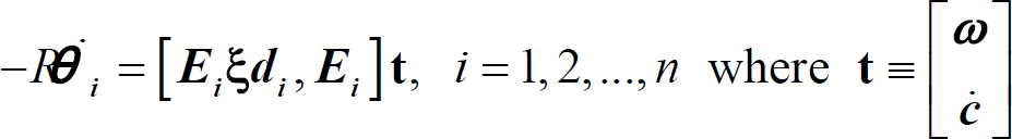
To design a robot with good performance, it is necessary to build the kinematic model for analyzing the velocity characteristics of the OMR. According to the velocity relationship of the driving roller and the passive roller as shown in Fig.1, the velocity of the driving roller centre
The maximum velocity of the robot is a criterion for


evaluating the design in our case. Taking into consideration, the special mechanism of the omni-directional wheel, analyzing the maximal magnitude of velocity is important for designing a robot with good performance. It can also be used consequently to define the arrangement of the omni-directional wheels, e.g. how many wheels will be used and in what direction it should be arranged, etc. Therefore, it is an indispensable step for studying the omni-directional mobile robot.
With the ability of translate along any arbitrary direction, the trajectory can be composed of a piecewise translation motion, therefore we only take into account the translational velocity, i.e.

To work out the maximum velocity in some direction (β) of the robots, the problem can be described as determining the maximal magnitude of

maximum velocity curve
It is important to analyze the maximum velocity in different directions that the robot can achieve for high-speed motion planning. According to the maximum velocity curve, it is obviously better to coordinate the robot to move around the range of 0 degrees or 180 degrees.
Slip is a familiar phenomenon during the motion, so it must be taken into account for better control of OMRs. As we known, slip often appears during the period of acceleration of the wheel. Due to the special mechanism of omni-directional wheels, the maximum acceleration in different directions are different, to avoid slippage, and it is necessary to work out the maximum acceleration while the robot moves along some direction. We also need to avoid exceeding the maximum acceleration to prevent “skipping”. By performing practical experiments, we can obtain the conclusion as follows: if the motion can achieve a much higher maximum acceleration along some direction, it can achieve much less slip and stable acceleration in this direction; however, more slippage occurs. Meanwhile, for the purpose of high-speed motion planning, it is important to move in the direction with higher acceleration. In summary, analysis of the maximum acceleration along different direction plays a significant role in the motion planning of OMRs. To exhibit the superior performance of the omni-directional wheel, it is assumed that the motor can offer the torque needed for maximum acceleration.
Based on the theory of vehicle dynamics (Yu, Z.S. (1990)), while the OMR accelerates, the tangential force caused by the contact deformation between the driving wheel and the ground is the traction of the mobile robot. Rolling resistance couple resulting from the deformation of the wheel counteracts the rotation of the driving wheel, and the passive wheel is also subject to effects of the tangential force and resistance couple. The unitary force diagram and the force during the accelerating period of OMR are shown in Fig.4.

Analysis of forces acting on the OMR
Parameters are defined as follows:
According to the force diagram (Fig.4), the dynamic model of driving wheel and passive wheel are defined by equation (5) and (6) (Yu, Z.S. (1990)), Where m
d
is the mass of driving wheel, and m
p
is the mass of passive wheel.


There are two kinds of slip for the omni-directional wheel, which are the driving wheel slip and passive wheel slip. But for practicality, the slip of the driving wheel always occurs earlier than for the passive wheel. Therefore, only the slip occurring on the driving wheel is discussed in this paper.
Due to the symmetry of the omni-directional wheel arrangement, it is obvious that:

During the acceleration, J
p

Maximum acceleration in different directions
The maximum acceleration in the direction vector 30° is minimum according to Fig.5, therefore, we should avoid the motion in this direction to achieve a high-speed and highly stable motion plan. And it is commended to let the robot move in the direction vector 90°.
In our case where the omni-directional wheel is used for the OMR, the load condition is distinct when the robot moves along different directions, which results in differences in the motion efficacy. For an autonomous mobile robot, the power is usually supplied by a battery. It is very important to take the motion efficacy as a control indicator for the motion planning of an OMR.
Under the same conditions, we work out the motor consumption to compare the motion efficacy when the robot moves in different directions in this paper. The motor consumption is determined by motor torque T in equations (8) here for simplification, where W
a
and W
v
are the energy consumption in accelerated motion and uniform motion respectively, T
a
and T
v
are the motor torques in accelerated motion and uniform motion respectively, t
a
and t
v
are the time consumption in accelerated motion and uniform motion respectively, ε is the angular acceleration, and ω is the angular velocity in uniform motion.

When the direction of acceleration α is subjected to 0 < α < 30°, the force diagram is shown in detail in Fig.6, where
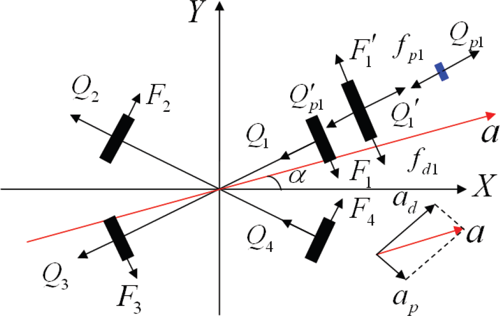
Forces acting on the OMR
During the acceleration, as mentioned above
Due to the symmetry of the omni-directional wheel arrangement, we know

When analyzing the uniform motion of the OMR, the forces are the same as shown in Fig.6, and we set a = 0 in equation (9).
To compare the motion efficacy while moving along different directions, we determine the motor consumption during accelerated motion and uniform motion along different directions under the same conditions, i.e. the initial velocity is 0, acceleration is

Energy Consumption in different directions
According to the analysis above, the maximum velocity, the maximum acceleration and the motion efficacy are anisotropic for the OMR. Therefore, the motion effects along different directions are distinct. We must consider these special characteristics synthetically in order to gain a better motion plan.
Considering the effect resulting from the anisotropy, first of all, we convert the value of maximum velocity (Fig.3), maximum acceleration (Fig.5) and energy consumption (Fig.7) into [0, 1], and especially convert the energy consumption curve into the motion efficacy curve by getting the reciprocal of the energy consumption value. Then we can deduce that V(β), A(β) and E(β) as the anisotropic characteristics of velocity, acceleration and efficacy, respectively. Finally, we introduce the Anisotropic-Function as shown in equation (10), where, k1, k
2
and k3 are functional weights of velocity, maximum acceleration and energy consumption in Anisotropic-Function respectively, so we can define k1 + k2 + k3 = 1.

The Anisotropic-Function value is an indicator to weigh the motion effects in the corresponding direction, where the higher the value, the better the motion effects in this direction will be. There will be different motion effects in the same direction with different weights denoted by the Anisotropic-Function, i.e. different trade-offs can be achieved by varying the weights. To highlight the impact of motion efficacy, we can increase the functional weight k3, for example, we take k1 = 25%, k2 = 25%, k3 = 50%. Therefore, the direction corresponding to the maximum value of the Anisotropic-Function is the optimum motion direction for the expected motion effect. Based on the motion direction worked out by tAPF, according to the Anisotropic-Function value of each direction, we regulate the motion direction to achieve the optimal motion planning. According to the Anisotropic-Function and the analysis above, we can get the Anisotropic-Function curve shown in Fig.8.

Anisotropic-Function Curve
According to the Anisotropic-Function of OMRs, we can achieve optimal motion by regulating the motion direction worked out by tAPF. Whereas, to achieve collision-free motion planning, not only the characteristics of the OMR be considered, but we also need to take into account the information of dynamic environment, obstacles and goal. Because the motion along the optimum direction may not result in the optimum path plan, the VMDA that the robot can avoid collision must be determined. Meanwhile, the path length will directly influence the speed and efficacy of motion planning, so the VMDA for the shorter path must also be determined.
VMDA for Collision-free Path
While regulating the motion direction according to the Anisotropic-Function, we did not consider the influence of the obstacles; therefore, it is possible to achieve high-speed motion planning without obstacle avoidance.
In order not to take into account the influence of avoiding obstacles for high-speed motion planning, when the threat of obstacles is big, the range for the robot to regulate the motion direction will be small, i.e. the threat of obstacles determine the variable of motion direction.
At the relative velocity
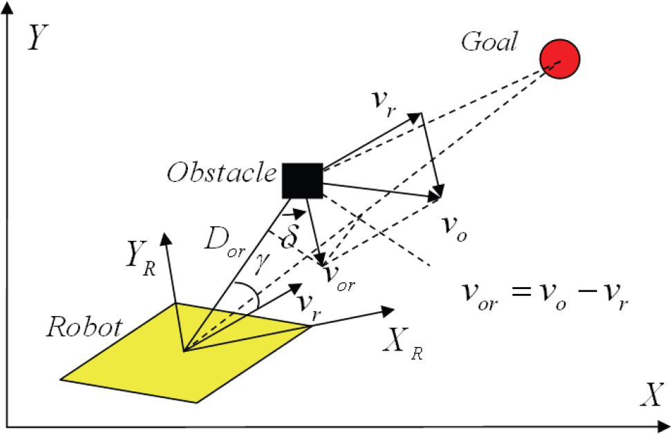
Effect on APF caused by relative movement
The threat of obstacles is determined by the relative position and velocity between robot and obstacles. In other words, the time mentioned above can be considered as a key factor that determines the threat of obstacles (Cao, Q.X. et al, (2006)). Therefore, the time is noted as an impact factor to define the variable angle in this paper. According to analysis, the variable angle βo can be modeled as shown in equation (11). Where k
a
and k
b
are the coordinating parameters.

Varying the direction in the range of βo calculated by equation (11) will not influence the avoidance effect, which is called the VMDA for collision-free path. When there is more than one obstacle, taking the minimum of the VMDA as the final safe area is the area we can vary the motion direction.
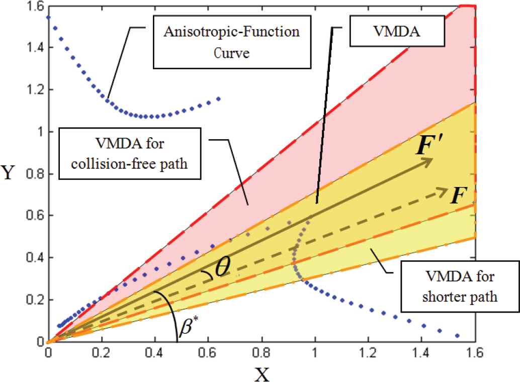
The maximum velocity in each direction is shown in polar coordinates, and the line V 0 V 90 is the maximum velocity curve from 0~90° (Fig.10). For example, the length RA is the maximum velocity in the direction of β. For high-speed motion planning, the length of the path is the important indicator. Accordingly, to achieve optimal motion planning, it is necessary to ensure that the path varied by the Anisotropic-Function is shorter than the one resulting from tAPF. As shown in Fig.10, RA is the motion direction resulting from tAPF, G is the goal, and GB is the vertical of V 0 V 90 , therefore, when the robot moves along RB, the distance between the robot and the goal will be the minimum. GC is the symmetrical line of GA with regard to GB, it is obvious that if the robot moves in the angle range of β s , the distance between robot and goal will be nearer than the one in the direction of β, i.e. the motion along the direction in the shaded region (βs) will achieve a shorter path, and βs is called the VMDA for a shorter path.

VMDA for a shorter path
Traditional APF (tAPF)
Motion planning is to determine a collision-free path from the start position to the goal. The basic principle of APF is to construct attractive potential fields around the goal to attract the robot and to construct repulsive potential fields around the obstacles to force the robot away from it. There have been a lot of classical research on APF, with different kinds of attractive and repulsive potential fields that has been introduced. In our study, we take the APF proposed by Khatib (Khatib, O. (1986)) as reference to derive the suitable motion planning for an OMR, and the artificial potential field is defined in equation (12).
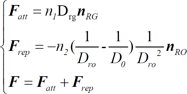
Where
With the characteristics of anisotropy, the motion in different direction results in different motion effects. APF is widely used in the motion planning for mobile robots, but the application of tAPF to OMR, cannot fully exhibit the motion advantage of OMR. Therefore, considering the characteristics of an OMR, we introduce the revolving factor into tAPF to coordinate the resultant force direction of APF. In this algorithm, the optimal motion direction we need is worked out in the VMDA determined according to the collision-free and shorter path principle.
Generally speaking there are two main approaches in using the total potential field force to control the motion of the robots. One approach is to use the total force as the control input or as part of the control input. The other is to use the total force as steering control (Ge, S.S. & Cui, Y.J. (2002)). To exhibit the potential of an OMR, we use the latter, i.e. the motion direction is determined by the Anisotropic-Function and the VMDA.
In this paper, the improved motion planning can be derived from the process as follows. First of all, according to tAPF, the motion direction can be deduced, for example, it is denoted by the force


Motion direction resulting from iAPF
According to the analysis above, we introduce the equation (14) to obtain the new resultant force denoted as
The motion velocity is determined by the distance between robot and obstacles. When the robot is far away from obstacles, the velocity will reach the maximum. When the distance is less than some threshold (D
0
), the velocity will be reduced. At this moment, the velocity will be proportional to the relative distance between the robot and obstacle as it is no longer affected by the functional weight k1 of the Anisotropic-Function.

From the analysis we mentioned above, we can build the velocity model in equation (15), where, v max is the maximum velocity value in the motion direction. k o is the coordinating parameter.
Simulation Studies
With the guarantee of reaching the goal without colliding with any obstacles, high-speed and highly efficient are the main indicators for efficient motion planning. Therefore, in order to validate the effectiveness of the motion planning mentioned in this study, we carry out a simulation in Matlab to analyze and compare tAPF to our iAPF. In the simulations, we compare the time and the energy expended at the same initial condition while performing a similar task. In order to fully evaluate the improved motion planning model, the path length and the average velocity are also compared.
In the simulation by varying the k1:k2:k3, we can make a trade-off between the speed, the stability and the efficacy. So we take different sets of k1:k2:k3 to determine the optimal functional weights. The initial setup for the simulation is shown in Table 1, where all of the values are determined according to the real robot. The maximum velocities and accelerations in different directions are obtained according to the values shown in Fig.3 and Fig.5 respectively. In the simulation, the robot, obstacles and goal are assumed as unit masses, and the initial position of robot, obstacles and goal are fixed randomly. The speed of obstacles and goal are also random, and the initial speed of robot is zero. To obtain the universality, 1000 random simulation experiments for one set of k1:k2:k3 were carried out, and the path length, average velocity, time consumption and energy consumption are analyzed. Under the same conditions, the simulations with the traditional and improved motion planning are both carried out.
Setup for simulation (SI units)

Setup for simulation (SI units)
By varying the weights with an interval of 1 percent, we traverse all the values in (0, 1), and ensure that k1+ k2 + k3 = 1, i.e., we vary the k1, k2, k3 to take the weights from 1% to 100%. The simulation results are shown in Fig.12. In the Figure, every grid corresponds a set of k1, k2, k3, and the color of the grid records a percentage improvement of our iAPF over tAPF in the 1000 simulations. Where, the x-axis is k1, and y-axis is k2, and k3 = 1 - k1 - k2.
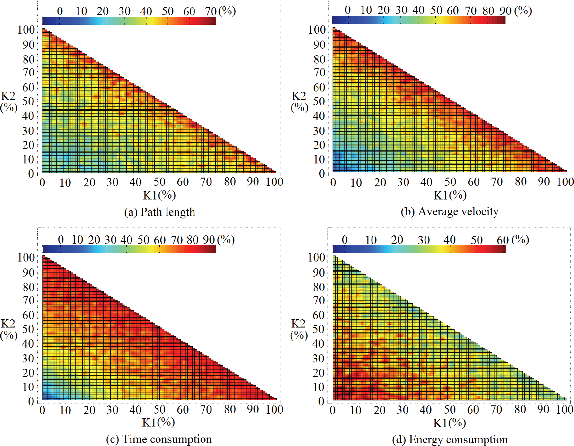
1000 random simulation results
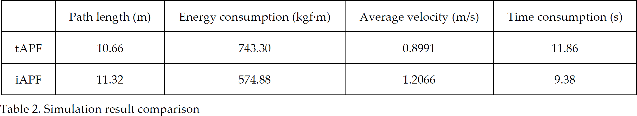
According to the Fig.12, we can select different sets of k1, k2, k3 for the iAPF to satisfy different objectives. For example, if speed of planning is weighed as more important than efficiency, we set k1 = 50%, k2 = 50%, k3 = 0%. Therefore, the results in Fig.12 can be used as a reference to obtain the motion plan that meets our pre-requisites. One of the simulation cases is presented in this section as shown in Fig.13, where k1 = 50%, k2 = 25%, k3 = 25%. The results of path length, energy consumption, average velocity and time consumption are compared between tAPF and iAPF in Table 2. From these data, we can conclude that with the right set of k1, k2, k3, the iAPF distinctly outweighs that of tAPF.

Trajectory comparison of tAPF and iAPF with same initial setup
Simulation result comparison
The acceleration variable in the Anisotropic-Function is to weigh the stability in different directions, but the simulation in this study do not consider the occurrence of skids, therefore, only the high-speed and highly efficient cases can be validated in the simulation, and the stability anisotropy will be validated in the experiments.
The simulation work cannot accurately simulate the practical cases due to the practical kinematic and dynamic constraints of the OMR robot. Therefore, we carried out some experiments to investigate the practical motion efficacy achieved using the improved motion planning method.
In the experiments, the omni-directional middle-size soccer robot (Fig.2) is used, and the omni-directional wheels are all side rollers (diameter 180mm) produced by our lab. The weight of the robot is about 15Kg, and the dimensions are 45×45×80mm.
For the omni-directional soccer robot, we use a laptop computer (CPU DuoT2130, Windows XP) as a higher level controller for the behavior-based control. The motion controller is composed of a DSP (TMS320LF 2407A) and a CPLD (Xilinx XC95144), used to control the robot velocity and to command the appropriate signal depending on the feedback encoder data to the motor drivers. Laptop computer and microcontroller are connected via RS-232 serial link in a 30 ms cycle at 19.2 Kbps.
The motors used for the omni-directional robot are Maxon DC motors (RE36 series, 24v, 70w), and the gearheads are Maxon's planetary gearhead series GP32A(Nominal reduction ratio 14:1). Three servo amplifiers (Maxon ADS 50/5 4-Q-DC) are applied between motion controllers. Each amplifier takes the analog output of the motion controller as its input and the output of the amplifier is then used to drive the motor. And the Maxon Photoelectric Encoder HEDL 5540 (pulse per resolution 512) is used for feedback in the robot.
The vision system of the robot is composed of Imaging Source DFK 21AF04 Color FireWire CCD Camera. In the experiments it tracks the object by the color at 30fps frame rate with a resolution of 640×480 pixels.
The experiment is carried out on the green carpeted field for RoboCup middle size robot play (12×8m, with reference to the RoboCup rules before 2007), where we take a red box put on a differential drive robot as the goal, 3 black differential drive robots as the obstacles. In the experiment the vision system of the omni-directional robot tracks the color of red and black to recognize either the goal or obstacles respectively. According to the simulation studies in order to achieve a high-speed and highly stable but with a low effiency motion plan, we set k1 = 50%, k2 = 50%, k3 = 0% in the experiment. Firstly, we let the goal move at an initial speed in the field. At the same time, the obstacles move at the set speed, and the omni-directional robot tries to catch the goal while avoiding collision with the obstacles in two different motion planning methods, the tAPF and iAPF proposed above.
Fig. 14 shows the experiment setup. The initial position and velocity of the robot, obstacles and goal of the experiment are set as shown in Fig.15, and the coordinates established, in which the centre of the robot is the origin, the front of the robot is Y axis.

Experiment scene with iAPF
The robot can reach the goal successfully while avoiding the obstacles in the experiment, and the efficacy of the iAPF is better than that of the tAPF. The results of the experiment are shown in Fig.15 and Table 3. In Fig.15, the theoretic trajectories are derived from the motion planning simulated by Matlab with the initial setup in Table 1, and the practical trajectories are the robot trajectories in the experiment. From the results shown in Fig.15, there are some obvious deviations between the theoretic value and experimental value, and the deviations are shown in Fig.16. And the reasons resulting in the deviations can be analyzed as follows. Firstly, although we tried the setup in Table 1 to approach a “real” case, there were also some deviations inevitably due to the uncertainty of the robot and the environment. Secondly, because of the characteristics of the omni-directional wheel, the robot tends to “skip” during motion, and the theoretical curves simulated by Matlab did not take the “skip” into account. Also we can obtain the following conclusion based on the data in Fig.16, and that is, there is less skip for the motion resulting from the iAPF than the one resulting from the tAPF to a certain extent, which validates the stability for the improved motion planning method analyzed in Section 3.
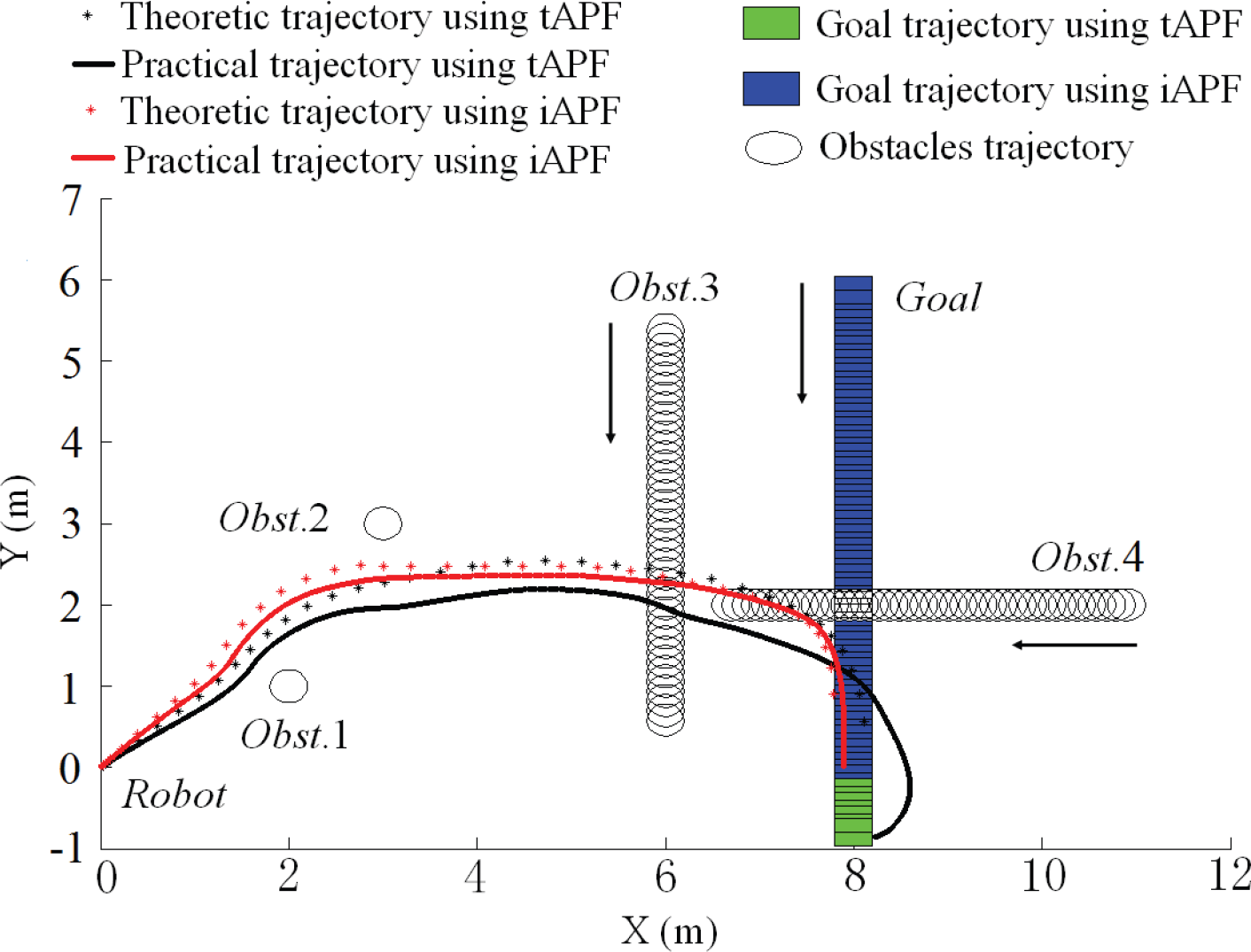
The theoretic and practical trajectory
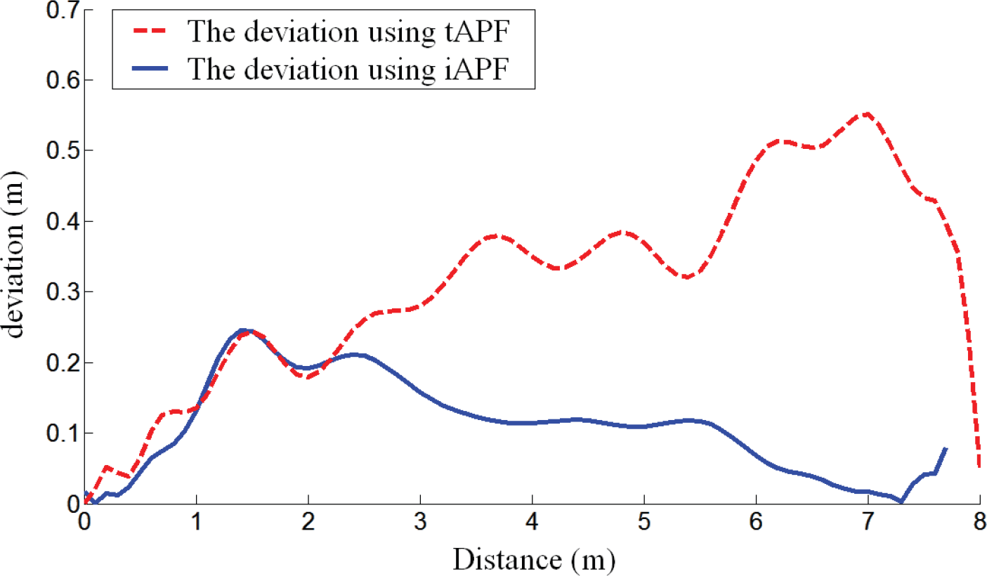
The deviations between the theoretic trajectory and the practical trajectory
Result data of experiment

In our experiment, we only took one set of values for k1, k2 and k3. However, according to the experimentation result we deduced that if other choices of k1, k2 and k3 are taken, different motion results will occur. Moreover, the results closely correlate to our simulation results.
Based on the analysis of the anisotropy of the velocity, acceleration and energy consumption, the Anisotropic-Function is proposed. Considering the collision-free path and shorter path as the pre-requisites of the motion plan, we determined the VMDR. And according to the Anisotropic-Function, the revolving factor is introduced into tAPF, so the motion direction is varied in the VMDA to achieve better motion results. Using the simulation data, we could vary the weights of the Anisotropic-Function to achieve the motion we need. The experiment results are coincident with the simulation. And both results validated the fact that the high efficacy of the iAPF concerning the path length, average velocity and time consumption. Also it is proved that the motion is much more stable according to our experiments while there was less energy consumption as proven in our simulations. Finally, an iAPF was proposed to exhibit the motion potential of OMRs.
But the practical factors, such as friction, were not considered during our computations of energy consumption. Therefore, in future research, it is necessary to take the friction model into account to obtain a more accurate energy consumption model for the Anisotropic-Function. Also, in this study the main objective is to find a high-speed, highly stable and highly efficient motion plan suitable for OMRs. Typical problems of tAPF, e.g. local minimum problem, are not addressed here, which is beyond the scope of this study. In our future research we will deal with these issues.
Footnotes
7.
This work is surported by the National High Technology Research and Development Program of China (863 Program), 2006AA04Z261, 2006AA040203, 2007AA041703.