
Abstract
It is shown how a holonomic and omni-directional mobile robot is designed towards indoor public services. Dual offset steerable wheels with orthogonal velocity components are proposed. The proposed wheel provides precise positioning and reliable navigation performance as well as durability. A fabricated prototype is introduced, then, an experiment is carried out.
Introduction
In recent years, there have been various trials to extend robotics technology to non-industrial applications, for examples, surgery, rehabilitation, floor cleaning, building patrol and so forth. A variety of technological achievements have been accumulated owing to the fast development of personal computers, sensors, and information technologies. A new mobile robotic system is under development towards indoor public services, as shown in Fig. 1. Major components are a mobile robot, a manipulator, a hand and trailers. A key concept of the mechanism is a reconfigurability based on the modularity. This paper mainly focuses on the development of the practical holonomic omnidirectional mobile robot. Among the many possible alternatives of the wheel mechanisms, the simplest one would be a differential steering nonholonomic mobile robot. In spite of the mechanical simplicity, control is difficult due to the nonholonomic mechanical constraint. A holonomic omnidirectional mobile platform provides control simplicity in various applications, such as autonomous navigation, mobile manipulation and trailer control. Easy development of control algorithm and the rich behaviour are major reasons why the holonomic omnidirectional mobile platform is desirable. Our target is limited to the indoor applications. The mobile robot will experience various kinds of floor dinditions such as concrete, carpet, tile and so forth. Therefore, reliability and durability is significant.
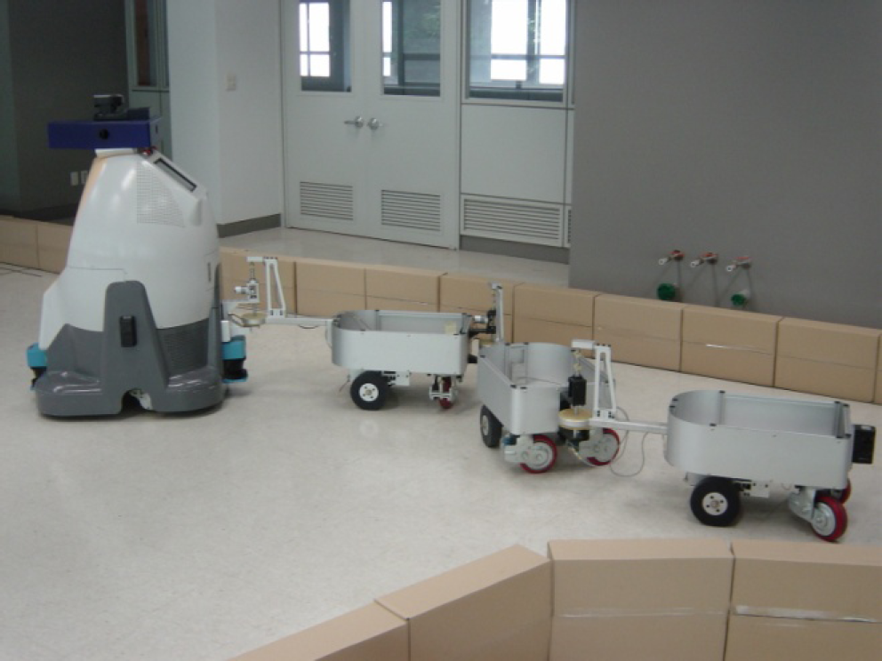
The prototype of a service robot.
So far, various kinds of omnidirectional wheel mechanism have been proposed. A typical approach is to use a universal wheel which is composed of a series of rollers along the rolling direction, for example, see (Muir and Neuman, 1987). Since using a universal wheel causes many problems such as vertical vibrations and inaccurate positioning due to the discontinuity of contact, there have been many challenges to solve the problems, for example, see (Pin and Killough, 1994).
A synchronous drive robot can be built by using centered orientable wheels or off-centered orientable wheels. Steering and driving motions of each wheel are mechanically coupled by chains or belts, and the motions are synchronously actuated. Therefore, wheel orientations are always identical. Therefore, omnidirectional motion, i.e. motion in any direction, can be achieved by steering wheel orientations to the desired velocity direction. However, the orientation of the robot chassis cannot be changed. Sometimes a turret is employed to change the body orientation. Most significant advantage of the synchronous drive robot is that the omnidirectional movement can be achieved by using only two actuators. Since the mechanical structure guarantees synchronous steering and driving motions, less control effort is required for motion control. Advantages include that the odometry information is relatively accurate and driving forces are evenly distributed by all the wheels. Drawbacks are: 1. Complicated mechanical structure 2. If there exist backlashes or loose coupling of chain transmission, velocity differences between wheels may take place. 3. In order to achieve omnidirectional movement, wheel orientations should be aligned to the desired velocity direction before movement, due to nonholonomic velocity constraints.
In spherical wheels, the rotation of a sphere is constrained by rollers which make rolling contact with the sphere. Roles of rollers are divided into driving rollers and supporting rollers. The sphere is driven by actuation of driving rollers. The rolling contacts provide nonholonomic constraints and the resultant motion of the sphere module becomes holonomic. This fact implies that the robot can be moved with any desired linear/ angular velocities at any time. By using the sphere wheel, a holonomic omnidirectional mobile robot can be developed and the robot achieves smooth and continuous contact between the sphere and the ground. However, design of a sphere supporting mechanism is difficult and payload is quite low due to a point contact. Another drawback is that the sphere surface can be polluted in a dirt ground condition and it is difficult to overcome irregular ground conditions. These drawbacks limit the practical application area of the sphere wheel. An example of using sphere wheels can be found in (Asada, Sato and Bogoni 1995) and (Ferriere, Campion and Raucent, 2001)
On the other hand, omnidirectional movement also can be achieved by using a conventional wheel. Many of the AGV's wheel module possesses centered steerable wheels which provides nonholonomic and omnidirectional movement. On the contrary, off-centered steerable wheels (offset caster type) provide holonomic features, i.e, arbitrary translational and rotational motions are available without changing wheel configurations. Examples of such mechanism can be seen in (Hanebeck, et al., 1999) and (Wada and Mori, 1996). Design issues of omnidirectional wheel mechanisms are well addressed in (Ferriere et al., 1996).
The rest part of this paper is organized as follows. Detailed illustration of the developed mobile robot will be given in section 2. A fabricated prototype and system configurations for the experiment will be introduced in section 3. Section 4 shows a result of the experiment. Finally, some concluding remarks and future works will be presented in section 5.
Robotic mechanisms for “movement” can be classified as legged robots, caterpillar or wheeled mechanisms for rough terrain, multi-body mobile robots and wheeled mobile robots. Wheeled mobile robots can be further divided into bi-directional or omni-directional and holonomic or nonholonomic mechanisms. Considering the classification of existing systems and target environments, design requirements for the mobile robot were summarized as follows:
Holonomic and omni-directional driving capability. Control simplicity. Reliable navigation regardless of floor conditions. Durability of the mechanism. Mechanical simplicity. Precise positioning performance.
Holonomic and omni-directional movements are essential requirements in order to achieve various mobile manipulations and trailer control applications. Control simplicity implies efficient design of path planner and tracking controller by excluding nonholonomic mechanical constraints. Reliability and durability issues are significant in practical applications. Complicated wheel structure and inaccurate positioning performances are major drawbacks of a universal wheel. It can be concluded that it is desirable to use conventional tires, which satisfy design requirements.
Passive holonomic omni-directional mechanism, which was our motivation and the starting point, can be seen everywhere in real life. Fig.2 shows offset caster wheel that provides holonomic and omni-directional movement. The aim is to build an active wheel mechanism that is similar to the reliable and simple passive caster wheels.

Passive caster wheels.
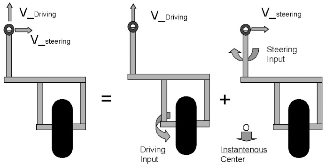
The easiest way to build an active caster wheel would be to employ two motors, one for steering and the other for driving as shown in Fig. 3. A driving motor is attached to the steerable wheel module, and the input is transmitted through a set of spur gears. In order to achieve holonomic driving capability, a longitudinal offset is nonzero.

An active caster design (example A). (top : front view, bottom : side view)
Kinematic relationships between the inputs and the resultant velocities applied to the mobile base at the pivot point (i.e. steering center of the wheel module) can be easily understood by Fig. 4. In Fig. 4, resultant velocity at the steering center can be represented by the vector summation. It is clear that the two velocity components are orthogonal.

Kinematic relations of an example A. Wheel offsets are seen from above.
Although the mechanism is quite simple, there are several problems. Major drawbacks are as follows:
The joint range of steering is limited by the length of the cable that is connected to the motor. A wheel becomes bulky due to the driving motor and large inertial torque is applied to the steering motor.
In this case, the robot motion should be carefully controlled because of the limited joint range of steering. In order to solve these problems, it is desirable to move the driving motor to the mobile base.
An example of such design is presented in Fig.5. Angular velocity of driving is transmitted using the shaft which goes through the center of steering axis. Accordingly, the resultant angular velocity of the wheel ω
d
is obtained as a following equation.


An active caster design to move the driving motor to the robot base. (Zero lateral offset: example B. Nonzero lateral offset: example C)
k g implies gear reduction of driving, ω d_motor is a driving motor input and ω s is a steering angular velocity. Equation (1) implies that the driving input ω d_motor is coupled with the steering angular velocity ω s . Suppose that the lateral offset is equal to zero. Then, the kinematic relations can be represented as shown in Fig. 6.

Kinematic relations of the example B.
From Fig. 6, it can be seen that the two velocity components are not orthogonal any more. This fact implies kinematic ill-condition between the input space and the output velocity space. As the instantenous center moves far away from the wheel position, both motors should make high speed rotation in order to achieve unit output velocity. Since it is not easy to increase maximum angular velocity of the motor, maximum speed of the mobile robot is decreased due to the velocity coupling between steering and driving inputs. The design issue is to decouple two velocity components, i.e. to make orthogonal resultant linear velocity of steering and driving by the appropriate design.
We propose a dual offset steerable wheel mechanism as shown in Fig. 7. Mechanical structure is similar to the case of Fig. 5. Fig. 7 illustrates the kinematics of the steerable wheel with both longitudinal and lateral offsets. Suppose that the longitudinal offset and the lateral offset is represented by a and b, respectively.
Kinematic relations of the example C (Proposed design).
Our purpose is to decouple two velocity components and the instantenous center of rotation should be located at the point which can be seen in righthand of Fig. 7. In such a case, the angular velocity of the wheel is determined as ω
d
= −k
g
ω
s
, from the equation (1). As a result, following equation can be obtained.

, where b is a lateral offset and r is a radius of wheel. Notice that the two velocity components are orthogonal for the dual offset wheel if the kinematic parameters satisfy the equation (2). This orthogonality implies well-conditioned kinematic model. With the limited maximum velocity of the motor, the dual offset wheel mechanism can be driven faster than the other mechanisms. Kinematic model of the example A and C are exactly same. Using the dual offset wheel mechanism, a mobile robot with two active steerable wheel is developed as shown in Fig. 8.
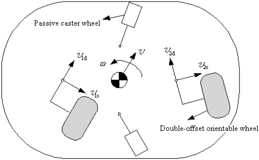
A mobile robot with two dual offset wheels.
There are two active wheels and two passive casters. Under the given translational and rotational velocities of the mobile robot, linear velocities at the pivot point which connects wheel and the mobile robot can be computed. Since we already have the single wheel kinematics, the kinematic model of the holonomic omni-directional robot in Fig. 8 can be derived easily. The minimun number of the wheel module is two. Additional active wheels can be added without any additional constaint.
A prototype is fabricated as shown in Fig. 9. Same wheel mechanisms are also adopted in the robot shown in Fig.1. There are two active dual offset wheels driven by blushless DC motors and two passive casters. Passive casters contain suspensions in order to assure stable contact with the ground. The maximum translational velocity is 1.5 m/sec. Control hardware includes onboard Pentium PC, customized signal interface boards and servo amplifiers. 18 ultrasonic sensors are equipped for detecting obstacles. Two ultrasonic sensor interface board are employed and the required sampling time for scanning is less than 110msec. Total weight of the system is approximately 80kgf and the size is 500 mm × 700 mm × 600 mm. Fig. 10 shows a prototype of the dual offset steerable wheel. A radius of the wheel is 66mm.

A prototype of the mobile robot.
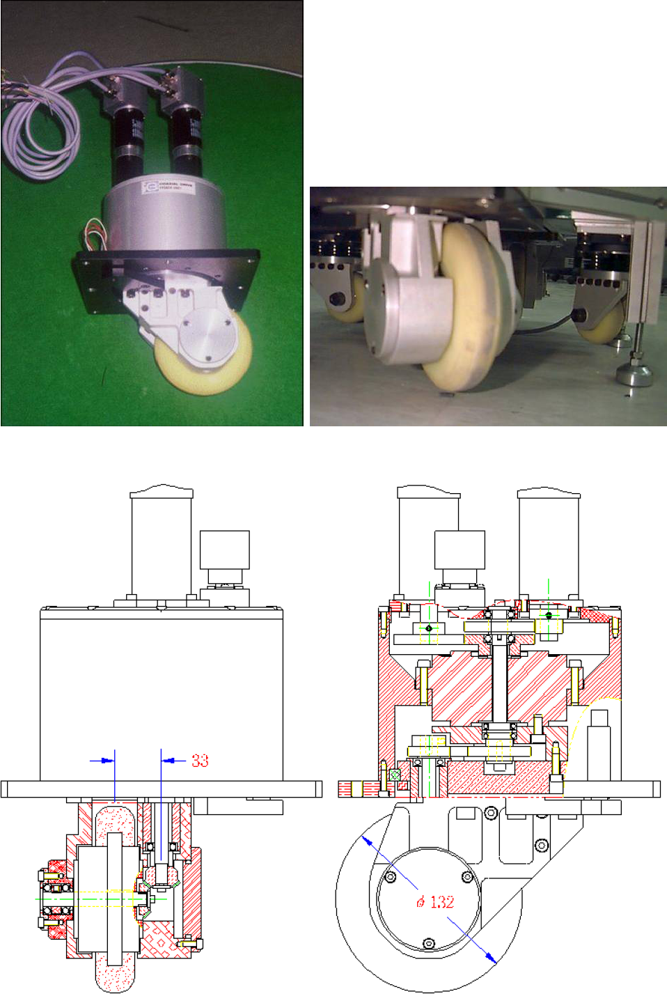
A prototype of dual offset active steerable wheel.
Our current system configuration for an experiment is presented in Fig. 11. Once user gives desired motion of the robot using the graphic user interface, inputs are generated by the off-line motion planner. Computed results are sent to the robot using the TCP / IP communications, then the robot is driven.

System configuration.
The position and the orientation of the robot is estimated by the camera attached to a ceiling, then Cognex vision system returns the result to the user interface. The camera view covers 2.1m × 1.6m of the robot movement on the ground. The estimation error is less than
Joint velocity control is carried out by applying the conventional PI controller. D gain could not contribute to improve velocity control performance in this case. After the appropriate gain tuning process, root mean squared tracking error was less than 3% of the reference inputs.
An experiment of driving was carried out. At this stage, the robot was driven by the programmed inputs without any path correction algorithm. The reference trajectory was set to be a rectangle (1.2m × 1.2m) and there was no change of the orientation. Fig. 12 presents the resultant trajectory of the experiment. Maximum positional error was approximately 8cm from the reference trajectory. The robot made constant acceleration and deceleration. The maximum speed of translation was set to be 0.3m/sec.
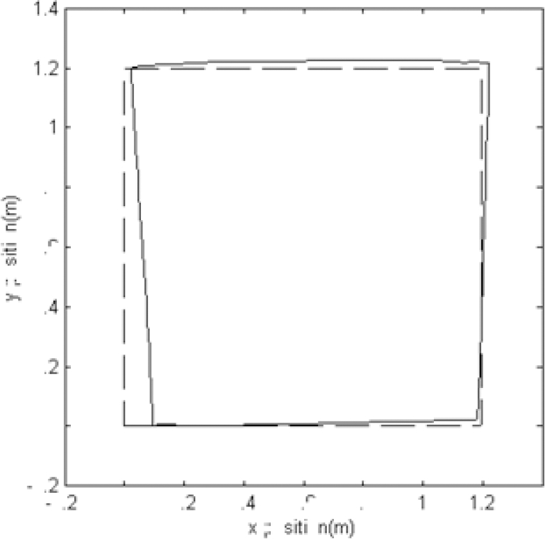
Resultant trajectory of an experiment.
The dominant source of error would be slippage and kinematic parameter modeling error. Analysis and systematic calibration for the odometry error are well addressed in (Borenstein et al., 1996) for the two wheel differential mobile robots. However, the analysis on the proposed mechanism is quite complicated problem and it remains as a future work.
In order to evaluate the effect of servo control performance, numerical computation is carried out. Fig. 13 shows four reference velocity inputs. Fig. 14 presents estimated joint velocities from the encoder signal. It is clear that the joint velocities are precisely controlled. A numerical integration was carried out using the estimated velocities, then the resultant trajectory is presented in Fig. 15. Fig. 15 shows the path from the robot's odometry. If there were neither slippage nor modeling error, the resultant trajectory would be Fig. 15. This result clearly shows the effect of slippage. This kind of error might be minimized by the careful motion control considering the mobile robot dynamics. Since dead reckoning errors are inevitable in practice, position estimation and path correction should be carried out, which remains as a future work.

Reference joint velocities.

Experimental joint velocities.

Odometry path under the open loop control inputs.
Design issues of holonomic and omnidirectional mobile robot were presented. The dual offset steerable wheel was proposed and it was shown that the proposed wheel mechanism has well conditioned kinematics. Prototype of the holonomic omnidirectional mobile robot was fabricated and introduced. An experiment was carried out and the effect of slippage was clearly evaluated.
Footnotes
6. Acknowledgment
This research was supported in part by the MKE(The Ministry of Knowledge Economy), Korea, under the National Robotics Research Center for Autonomous Navigation Technology support program supervised by the NIPA(National IT Industry Promotion Agency). This research was also supported by Basic Science Research Program and Mid-career Researcher Program through the NRF grant funded by the MEST. This work was also supported by the ITRC support program.