
Abstract
It is an important criterion for unmanned aerial vehicles (UAVs) to land on the runway safely. This paper concentrates on stereo vision localization of a fixed-wing UAV's autonomous landing within global navigation satellite system (GNSS) denied environments. A ground stereo vision guidance system imitating the human visual system (HVS) is presented for the autonomous landing of fixed-wing UAVs. A saliency-inspired algorithm is presented and developed to detect flying UAV targets in captured sequential images. Furthermore, an extended Kalman filter (EKF) based state estimation is employed to reduce localization errors caused by measurement errors of object detection and pan-tilt unit (PTU) attitudes. Finally, stereo-vision-dataset-based experiments are conducted to verify the effectiveness of the proposed visual detection method and error correction algorithm. The compared results between the visual guidance approach and differential GPS-based approach indicate that the stereo vision system and detection method can achieve the better guiding effect.
1. Introduction
With successful application in many areas, unmanned aerial vehicles (UAVs) have been a popular research topic in the field of robotic systems. Landing safely is an important process in the flight control of UAVs. Most traditional landing control methods are based around radio waves and the global navigation satellite system (GNSS). However, the UAV landing process is mainly remote controlled by experienced operators in environments where there is electromagnetic interference. In this eye-in-loop process, operators estimate UAV flight states using the human visual system (HVS). Since recovery mode depends on the experience of the professional operators, dangerous or fatal mistakes are inevitable when the operator's attention is required for one hour or more. It is therefore desirable to develop UAV autonomous landing technology by using vision-like technologies. The development of an UAV autonomous landing system involves many areas of knowledge. Although there has been significant research [1,2] on designing analogous systems and algorithms in the area of UAV autonomous landing, guiding UAV landing remains a challenging task.
The design of visual detection, tracking and vision measurement algorithms are key factors for constructing an autonomous guiding system using computer vision. Stereo visual localization is inspired by the human vision system (HVS) and supported by stereo vision measurement theory, which has been involved in many applications [3]. During flight, aircrafts often move through a cluttered background (e.g., cloudy sky, forest, mountain, the ground). Furthermore, rapid movement of UAV leads to significant background variation, which increases the difficulty of target detection and tracking. Even if the flying vehicle is automatically detected, measurement error still affects localization and guiding accuracy. This inaccuracy is particularly noteworthy in long-distance scenarios.
To address the issues noted above, this paper proposes and develops a saliency detection method combined with a filtering correction. This work is in accordance with the developed ground-based stereo vision guidance system [16]. The combination of computer vision and autonomous landing control can avoid the influence of electromagnetic interference, and increase the robustness of the landing system. The successful realization of the proposed visual guidance system primarily depends on the following two contributions.
A long-baseline architecture that separates binocular cameras is proposed for the ground visual guidance system. Specifically, two cameras are independently installed on the pan-tilt units on the ground to imitate the HVS shown in Fig.1. Under such circumstances, the ground stereo system captures sequential images of the flying vehicle. Algorithms of target detection and localization are developed to obtain spatial coordinates for the landing of the aerial vehicle. The ground system sends the coordinates to the on-board autopilot via the specified data link in order to guide the landing of the UAV.
A saliency visual detection algorithm inspired by the human eye is employed for detecting the flying vehicle from the captured images. Furthermore, an extended Kalman filter (EKF) is implemented to estimate the spatial coordinates of the UAV and to reduce localization errors.

Architecture for the ground-based fixed-wing UAV guiding system
The remainder of this paper is organized as follows. In section 2, works related to UAV landing technology and the saliency detection method are reviewed. Section 3 formulates the UAV autonomous landing problem and describes the architecture of the visual guidance system. A saliency-based target detection algorithm is proposed in section 4. Parameter initialization and tuning with typical scenarios is also considered. Section 5 develops the flying vehicle localization algorithm by fusing the detected image coordinates and the PTU angles. Moreover, a trajectory estimation and correction algorithm combined with EKF is also proposed for improving localization accuracy. Eventually, outdoor flight experiments are conducted to validate the effectiveness of the proposed algorithms in Section 6. Finally, concluding remarks and future works are presented in section 7.
2. Related Works
Developing autonomous landing technologies is an important trend for the runway-mode of take-off-and-landing UAV systems. Types of autonomous guiding systems that have been developed for UAV navigation include ground vision-based, onboard vision-based and ground radar-based systems. The success of flying aircraft navigation is mostly achieved by using on-board sensors [4–5] such as the global positioning system (GPS), inertial measurement unit (IMU), on-board cameras and magnetometers. In recent years, methods [6–12] using airborne vision-based navigation methods for UAV accuracy landing have also been proposed. The tactical automated landing system (TALS), based on millimetre wavelength ground radar, was developed by the Sierra Nevada Corporation for autonomous landing [13]. The TALS is an all-weather ground station. However, there are also some disadvantages to the aforementioned autonomous landing systems. (1) Compared to airborne guidance technology, ground systems possess stronger computational resources and save costs. The payload of the UAV is limited, which functions as a strong restriction to sensor selection, considering their weights. Moreover, external artificial auxiliary markers included in several studies [6–12] are mainly used for guiding the UAV to land on the runway. (2) A GPS-based system is limited to satellite signals. However, in some circumstances, a GPS- denied environment can be quite dangerous for the UAV closed-loop control system in terms of landing manoeuvres. (3) A radar-based detector primarily employs microwaves and is extremely sensitive. Furthermore, as an active range sensor, it cannot avoid detection. They are also much more expensive compared to a visual system. Therefore, taking into account the above considerations, we primarily focused on developing a ground stereo vision guidance system [15–17]. By using a ground binocular camera system to guide the UAV's landing, many researchers have expanded work in the area of developing vision systems [14–18].
Another purpose of this research is to develop detection and tracking algorithms for the vision-based UAV guidance system. A range of methods have been presented [19] for the detection and tracking of a target using visual information, e.g., feature-based tracking, mean shift tracking and tracking by detection. However, target detection in the cluttered environment has some shortcomings. For example, local point feature-based detection can receive many local features in a cluttered environment. To solve this problem, Chan-Vese algorithms were applied to flying object detection on the ground-captured sequential images in our previous works [16, 17]. In this paper, we mainly focus on inspiration gained from the HVS. In particular, HVS responds sensitively to high textural contrasts, which are generally derived from discriminative directional patterns. Visual attention facilitates our ability to rapidly locate the most important information in a scene. The visual selective attention mechanism, also known as the visual saliency mechanism, enables humans to focus on a few striking visual objects in a rapid fashion when faced with a complex scene and to carry out the priority processing on these objects. In the case of human eyes, the visual saliency mechanism [20] realizes highly efficient information acquisition and the processing of images. Such image regions are said to be salient because it is much easier for the salient regions to get the attention of HVS. The saliency detection method primarily originates from the biological implications of human vision [20–22], because it is easy for humans to judge interesting objects within their region of view using binocular vision. Motivated by the above, in this paper, we introduce a detection framework combined with a ground vision guidance scheme and a saliency detection algorithm.
3. Framework
The typical process of UAV landing on the ground can be divided into three stages: approaching, descending and taxiing. The ground stereo vision system usually works within the descending and taxiing stages, once the UAV's engine is turned off. The guiding system, consisting of two independent modules, is located symmetrically on both sides of the runway near the UAV landing point, as shown in Fig.1. Each module is equipped with one camera on an independent pan-tilt unit. The two modules are independently connected to the computer. By using two cameras, binocular vision has a function similar to human eyes and can obtain 3D information about the targets.
The binocular vision measurement system mainly consists of image capture, aircraft detection and tracking and aircraft position calculation modules. The workflow of the position calculation system and vision system are shown in Fig.2. The airborne navigation system guides the aircraft into the field of view of the stereo cameras and the aircraft turns off its engine. The visual system with its two cameras has a wide view of the sky. Captured image sequences from the two cameras are sent to the data processing computer at the same time. The detection algorithm extracts the UAV's image position from the captured sequential images. At the same time, the localization algorithm uses the calibration data, target image coordinates and the feedback angles of pan-tilt units to calculate the UAV spatial coordinates and restores them. Combining the current UAV's spatial position with previous position information, a more precise trajectory prediction result can be achieved by the filter algorithm. Finally, the landing position and control information are sent to the guidance system of the UAV. The PTU vision system updates its rotating angles and drives the pan-tilt motors to track the UAV and to keep the image of the flying aircraft at the centre of the vision field.

Workflow of the visual guidance system
4. Visual Detection Algorithm
Target detection is an important technology for guiding UAV autonomous landing. Many research methods exist for object detection, including the background-difference method, frame difference method, feature extraction based method, optical flow based method, etc. The main challenge for detection in UAV landing problems lies in finding the UAV within a varied background composed of sky and land. Furthermore, the binocular solution will use the UAV's image coordinates as the input. Inspired by human vision characteristics, in this paper, we propose a saliency method for target detection.
4.1. Saliency detection method
A good saliency algorithm should highlight the entire salient object. Several methods have been highlighted in object saliency research, e.g., methods pertaining to the frequency domain and time domain methods. The proposed saliency detection method in this paper belongs to the frequency domain.
The problem of finding all objects in a scene and separating them from the background is known as figure-ground separation. The natural images that HVS is interested in often contain special content. These contents are part of the image and sparsely distributed. Therefore the picture can be regarded as consisting of a background and the sparse distribution of salient targets.
A grey-scale image will, for example, exhibit the following structure:
This method primarily involves seven key steps, as shown in Fig.3. The full image processing results that applied this algorithm are also shown in Fig.3.
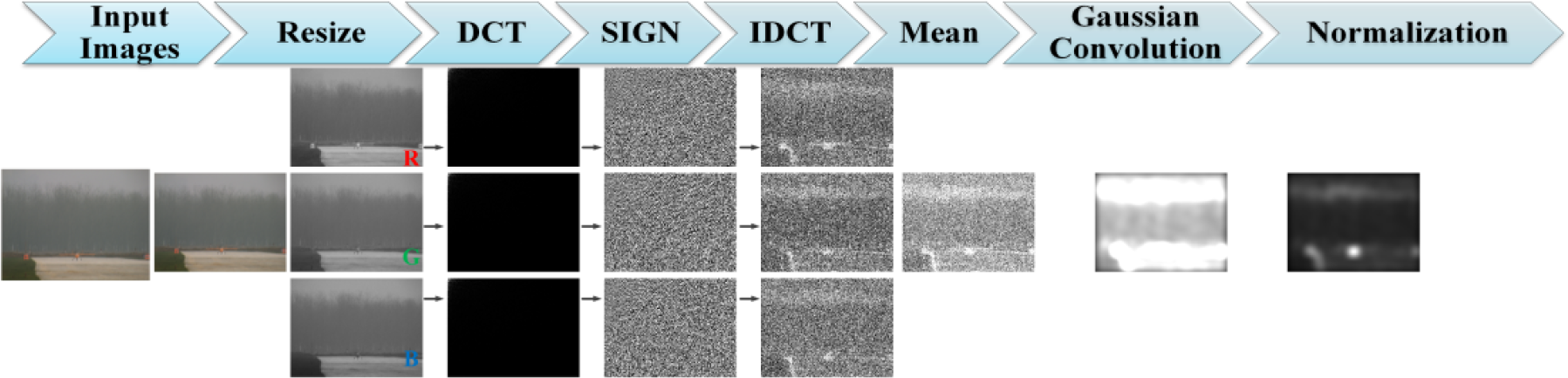
Process of saliency detection algorithm: resize, DCT, SIGN, IDCT, mean, Gaussian convolution and normalization
In this paper, we use the nearest neighbour interpolation algorithm to resize the initial input image
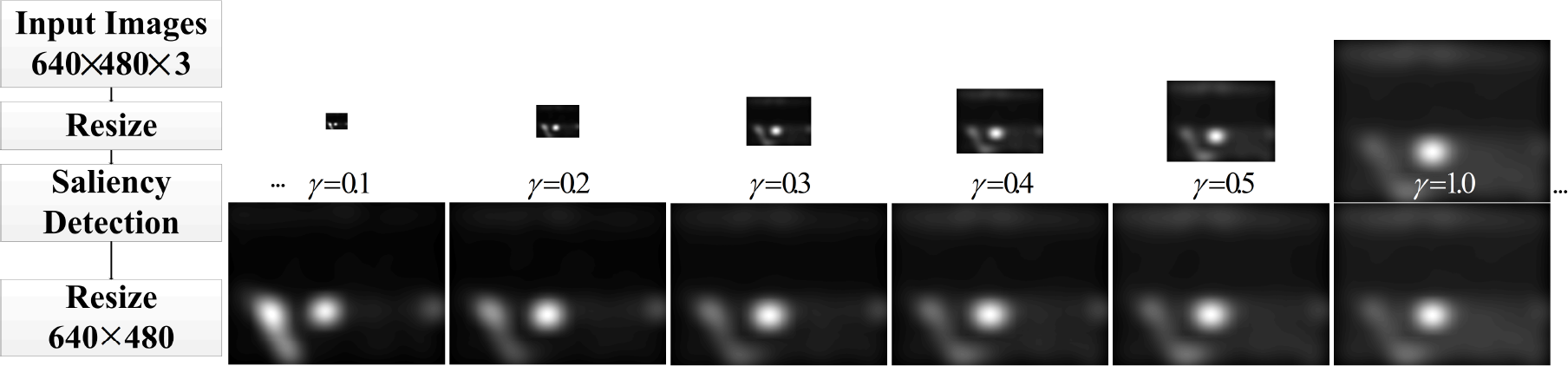
Saliency detection results and the algorithm running time for a different γ
The DCT is a type of orthogonal transformation that transforms data from the spatial domain to the frequency domain. The primary information of the signal is concentrated on a small number of low frequency coefficients. The definition of DCT can be described by:
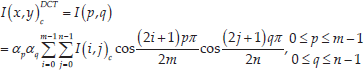
where
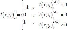
The sign operator, defined by Eq.(2), is applied to the transformed image
The IDCT of the image is defined by the following equation:

A mean operator is applied to the three image channels using the following definition:

Gaussian convolution is adopted to get rid of noise in the image after mean operation.

in which σ is the parameter of Gaussian variance and the convolution operator is defined by:

In this process, different σ will also have an effect on the final results, as shown in Fig.5.

Saliency detection results for different σ
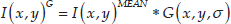
Finally, a normalization operator, defined in Eq.(7), is applied on the filtered images. Following normalization, the pixel value of images is re-scaled to the range
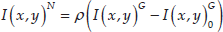
where
4.2. Index for parameter selection
When people observe a scene, the focus of the eye is constantly adjusted. However, the same scene is seen differently at an altered distance. Parameters of scale factor γ and σ are related to the detection results for imitating the distance factor. In this paper, the evaluation for acquired information can be realized by calculating entropy. Entropy can be used to discriminate different characteristics and texture structures in different regions of images. In this way, entropy is used to calculate the anisotropy of the image. We will choose parameters based on the variation trend of the entropy value. Particularly, the calculation of entropy can be realized by Renyi entropy [23], defined as follows:

where q is an adjustable parameter. When q reaches 1, Renyi entropy is converted to Shannon entropy. By choosing different value of q, the entropy corresponding to different regions becomes more obvious. Considering the complexity of the computation and full use of parameter q, the value of q is set to 3 in this paper.
4.3. UAV image coordinates solution
The result obtained by the saliency detection algorithm comprises a significant image region. However, it is necessary to know the precise location of the UAV during the guiding process. Obtaining the precise image coordinate position of the UAV is key to the process of UAV guidance. This paper primarily employs the threshold segmentation method and the saliency image to deal with this problem. The threshold algorithm, used for determining the position of the UAV from the saliency region, is defined by:

where δ is the threshold. The threshold is primarily selected by our multiple experimental experience on the image dataset.
In order to obtain a precise image coordinate of the UAV, this paper uses the following average method to determine the UAV image coordinates

in which a is the number of nonzero pixels in
4.4. UAV detection and image coordinates' solution algorithm
Algorithm detection and image coordinates solution
5. Spatial Position Calculation Algorithm
In order to guide the UAV's landing, the spatial location must be calculated from the image coordinates. In this paper, the calculation algorithm is based on the binocular vision measurement principle. On the other hand, UAV detection must ensure that the UAV remains in the FOV via real-time control of PTUs. Updated rotating angles are also given in this section.
5.1. Binocular vision calculation algorithm
As shown in Fig.6, the world coordinates system is located on the origin of the coordinate system

Simplified coordinates based on the landing process shown in Figure 1
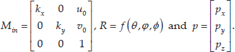
Based on the pinhole model, the relationship between the UAV's coordinates in the world frame

where λ is normalization coefficient,
Using the camera projective transform model (11), we can derive:

and

where

Hence, for any given point in
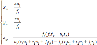
where fl and fr are the two cameras' focal lengths.
5.2. Rotation angles of the PTUs calculation algorithm
In this paper, we assume that the roll angles of the PTUs are 0°. Therefore, the pan angle θ and tilt angle φ of PTUs update parameters automatically to keep the flying aircraft in the centre of the vision field. The distance of the baseline between two PTUs is d, as shown in Fig.6. Based on the UAV spatial position's projection relationship, N is the projection of UAV on the

Eq.(16) can be used to determine the updated PTUs' angles:

5.3. EKF-based UAV spatial position fusion algorithm
5.3.1. EKF Prediction model
In order to improve the precision of our method, the data fusion algorithm, based on the extended Kalman filter, is discussed in this section. In the EKF design for this application, an estimation state vector is taken as follows:

where L and V are vectors describing the location of the UAV and the velocity in the world frame; Θ and Ω are vectors describing the angle and angular velocity of the PTUs.
Variables in Eq.(18) are defined by
More specially, EKF-based visual tracking methods estimate the UAV's state with given observations up to frame k. The relationship between the UAV's position and velocity is defined by
The relationship between the angular position and angular velocity of the PTUs is defined by

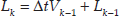
Then, the state transition equation is defined by

where
The estimated state covariance matrix at step k is defined by:

where
5.3.2. Measurement Model
In the binocular vision system, we can acquire the image data and the angles of the PTU. Thus, the measurement matrix is defined by

where
Based on Eq.(11), the measurement model is defined by:
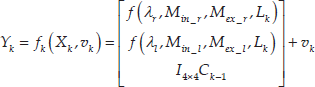
where
5.3.3. Correction model
Xk is updated by measurement Yk and covariance matrices. According to measurement model, the Jacobian matrix Hk of fk can be represented as:

Then, we get the Kalman gain Kk:

where Rk is the Gaussian noise covariance matrix of the sensors and


6. Experiments and Discussion
In order to verify the UAV guiding effect based on a binocular vision guidance system and the superiority of the saliency detection method, this paper adopts the fixed-wing UAV as flight test object and conducts offline and online experiments.
6.1. Experimental set-up
We constructed a set of ground-based guidance systems using a fixed-wing aircraft. The fixed-wing UAV applied in this paper is shown in Fig.7 and the parameters are shown in Table 1. The platform is installed using an IFLY-F1 controller. The control signal and position signal is transmitted to the UAV flight control system via radio stations on the ground.

Experimental equipment in the present work: (a) fixed wing UAV; (b) DGPS module inside UAV; (c) antenna used for sending signal; (d) two PTUs systems with camera
The parameters of the fixed-wing UAV

In addition, the UAV is equipped with a differential global positioning system (DGPS) module in order to ensure its flight safety. The DGPS signal is also easy to use for data comparison analysis. As the product manual of DGPS lists, the localization error of DGPS is less than 2cm 95% of the time. The frequency for recording DGPS signal data is 10 Hz, which is similar to the video recording frequency. When the UAV flight height is 60-100m and the distance from the PTUs is 400-500m, i.e., the approaching and descending stage, respectively, the system begins to prepare for landing guidance. The vision system uses a visible light camera. Two PTU systems select a stabilized biaxial gyroscope with high rotary speed (50 degree/sec) that supports the RS232 serial port in sending the command signal. Additionally, the real-time feedback status, including pan angle θ and tilt angle φ, can be achieved by the PTUs.
6.2. Analysis of target detection results
6.2.1. Parameters selection experiments
UAV visible light images captured by the camera are shown in Fig.8. A significant region for the UAV can be obtained at a speed of roughly 30m/s using the saliency method. A single image's initial size is 640*480 pixels. First, we need to determine the corresponding parameters in the saliency detection algorithm based on historical data. Using a set of flight tests, a sample dataset is collected. As shown in the Fig.8, we selected a typical source for sample data to analyse. The typical source includes the images that UAV appears in the different position of the air and the background is different.

Algorithm running time and Renyi entropy Re for different γ
In Fig.8, three typical images in different positions display the parameter selection process in order to conveniently describe the data processing results. The saliency detection algorithm in section 4.4 is applied to the image datasets using different scale factors.
In the parameter selection experiment, the range of scale factor γ is
Therefore, there are
Variations in entropy
Similarly, the corresponding saliency map is obtained according to Gauss convolution using different σ parameters. In the experiment, we also calculate entropy and entropy changes pertaining to the saliency map. For the all images in the dataset, the optimal size scale factor is set to 0.1. Parameter σ is in the range of

Saliency map and Renyi entropy Re for different σ: saliency map 1-6 for different images show when σ=0.01, 0.02, 0.03, 0.04, 0.05, 0.06
6.2.2. UAV detection experiment results
We applied the saliency detection algorithm to the flight experiments using parameters

Target detection using the saliency method and threshold algorithm: (a) the processing result for target detection of the UAV in the air; (b) the processing result for target detection of the UAV in the air with forest in the background; (c) the processing result for the UAV on the ground; (d) the wrong detection result for the UAV on the ground
We also found a wrong detection result, shown in Fig.10(d). A chair with same red color to the UAV is detected using the saliency algorithm. However, this algorithm was verified as suitable for detecting the salient region in an image. Thus, incorrect detection results may give rise to UAV spatial coordinate calculation errors. A filter (proposed in section 5.2) is needed to reduce errors based on recorded historical data.
6.3. Flight experiments
During the UAV flight test process, the ground control station transfers the physical coordinates of the UAV via antenna to guide the landing of the UAV at a speed of 30m/s. In order to verify the effectiveness of the visual detection algorithm, the ground control station records DGPS data, saliency automatic detection results and EKF- based estimation results during the landing process. As Fig.11 shows the comparison curves of the DGPS data, EKF estimation results and the UAV spatial coordinates attained by the visual method. The UAV begins to land about 250m away from the visual system.
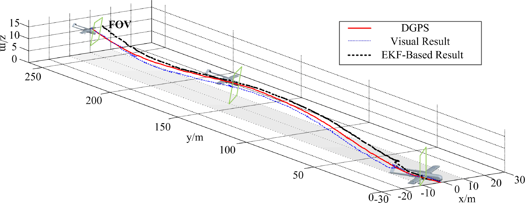
3D flight path results including the visual guidance result, EKF-based fusion result and DGPS data
In order to analyse landing precision, we define the absolute errors by
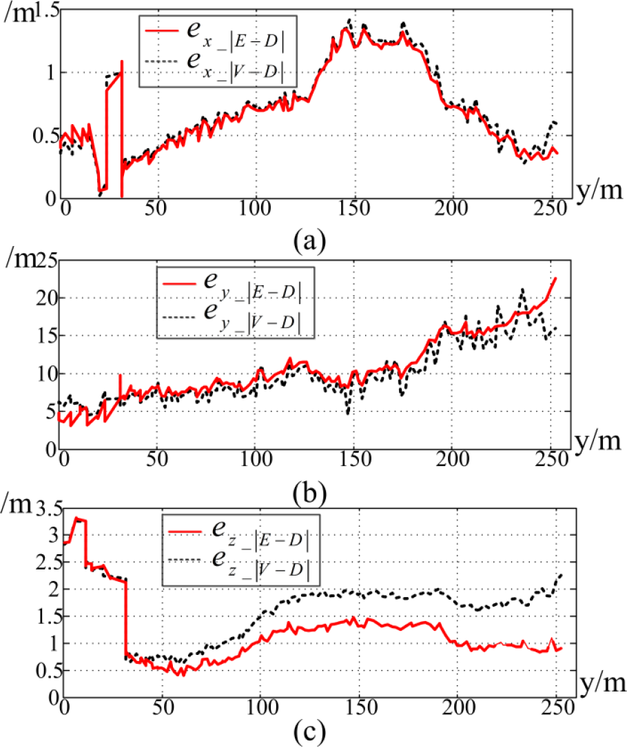
3D flight path errors between the visual guidance results, EKF-based fusion result and DGPS data
6.4. Comparisons with other works
Compared to existing research, we find that the autonomous landing results are similar to work presented in [6]. In Gui's work [6], an airborne vision-based navigation method is used for the accuracy of UAV landing. In addition, many additional infrared lamps are applied to increase landing precision. Our study attempts to imitate the HVS in order to avoid using additional auxiliary materials.
On the other hand, in our previous work [17], different visual algorithms were applied to this guiding system. To verify its effectiveness, we mainly compared the saliency-based calculation results with the methods proposed in [17]. A Chan-Vese (CV) model-based approach is proposed and developed for ground stereo vision detection and a region-of-interest (ROI) set-up is presented to improve real-time capabilities. We therefore primarily compared different detection-based calculation precision with detection algorithm running time. Fig.13 shows the running time for different detection algorithms running on a PC with 2.80 GHZ CPU and 6.00 GB RAM. The time for CV is longer than when using the saliency detection method. The iteration process increases the running time of the CV algorithm. By decreasing the size of image, the saliency method shows better detection efficiency compared to CV, snake and gradient vector flow (GVF) snake algorithms. The running time for the location calculation algorithm with EKF is 10 ms.

Running time for different detection algorithms
Table 2 shows the guidance calculation comparison results between the saliency and CV methods. It can be seen that the spatial coordinate's root-mean-square error (RMSE), based on saliency, is larger than the CV-based method. In [16], the detection region of the UAV is the region-of-interest (ROI), which is smaller than that detected by the saliency method. Thus, the calculated image coordinates for the UAV are more accurate than those identified in this paper. Detection errors decrease the accuracy of calculating the spatial coordinate. However, the EKF-based method used in the current paper improves the UAV spatial coordinates calculation results by 2.3%, 7.28% and 18.21%.
The root-mean-square error (RMSE) and precision improvement with EKF at each axis for different algorithms

7. Conclusion
Realizing aircraft self-recovery using bionic vision technology is an important indication for UAVs with high level performance. Addressing the UAV autonomous landing problem within a GPS denied environment, this paper constructed an UAV autonomous guiding system based on the HVS. Focusing on visual detection, tracking and the vision measurement problem, this paper proposed the saliency method and the UAV spatial position calculation algorithm by using the visual measurement principle in the UAV autonomous guiding system. In addition, according to the interference problem pertaining to UAV detection, this paper presented a method for forecasting and position correction based on EKF in order to reduce measurement errors. Finally, this paper carried out experiments using a fixed-wing UAV to test landing using this visual system. Experimental results and comparison results show that the proposed algorithm framework is simple and that the target detection effect is effective, which can satisfy the requirement of accuracy.
However, the shortcoming of this study is that salient regions selection depends on threshold parameters, which needs pre-training using historical data. Future work will aim to constantly improve the intelligent algorithm in order to raise the precision of the algorithm's position calculation within this framework.
Footnotes
8. Acknowledgements
The authors wish to thank Zhang Daibing, Niu Yifeng and Kong Weiwei for their assistance in developing the guidance system. We also gratefully acknowledge the support of the National Natural Science Foundation of China (61403410).