
Abstract
Inspired by biological systems, we seek to achieve natural dynamics and versatile locomotion for hopping or running robots by installing a series elastic actuator (SEA) in the joints due to its compliant property, passive adaptability and energy storage. However, robots equipped with these actuators have drawbacks in terms of substantial delay and limited bandwidth in their position control, especially when a robot has to choose its foothold while it is running at a demanding speed. To solve these problems, compliance control and adaptive position/torque control are introduced to a hopping- legged robot in this paper. The compliant performance of the robot can be improved through the intrinsic property of an SEA with a torque control algorithm. Combining the kinetics model and stochastic model of a 2-DOF robot, an adaptive position control with Kalman Filtering (KF) is developed to provide rapid convergent state estimation of the load on the robotic end-effector by solving the inverse dynamics. Validating the robustness and effectiveness of the proposed algorithm on our hopping-legged robot Tigger, the experimental results show very good position-tracking and disturbance-rejection, as well as flexible interactions while operating in a complex environment.
1. Introduction
In order to study and understand the principles of human and animal locomotion, lots of legged systems have been developed in the last twenty years. Roughly, these robots can be separated into two classes [1]. One class is of stiff-legged systems, which often have a rigid structure and many degrees of under-actuation, as well as use inertia driven movements to propel themselves forward. The rule for designing and controlling robots is ‘the stiffer the better’, which not only improves precision, stability and bandwidth of position-control [2], but also presents higher locomotion speed and lower vibration [3–6].
The other class of legged systems relates to those equipped with a force or torque sensor, such that a joint or the structure allows the robot to exploit natural locomotion with compliant control. There are two main methods to realize this feature. One is active compliance control of rigid bodies, in which a force sensor is mounted for real-time detection of external contact force on the robot joints or surface. Active compliant control is used to adapt the collision or impact, such as impedance control [7], position and force control [8], and current control [9]. For instance, the quadruped robots BigDog [10] and MIT-Cheetah [11], the humanoid robots COMAN [12] and KONG [13], and the single-legged robot Kenken [14] offer good stability and versatility. However, impedance control is difficult to achieve accurately in either position or force control, because position or force control has to switch mode according to different conditions, while current control needs the precision model of a robot.
Inspired by biology, an SEA is proposed by installing an elastic element between the gear unit and the load [2]. Compared with traditional joints, it has some advantages, such as precise force or torque control, low impedance and elastic energy storage [15,16], which have been widely used in some robots [17–19, 26]. In term of torque control, some of the literature has been expounded [22–24]. Besides torque control, position control also plays an important role in improving the performance of SEA-based robots in choosing the foothold or tracking the planned trajectory for versatile motions with visual sensors [27]. Lv [20] described an adaptive method for the position control in an SEA platform, while Zhu [21] designed a BP neural network to compensate for the non-linear characteristics of the spring of an SEA to realize the stable velocity control. But these research studies were only concerned with one joint.
For our research, we extended the principle of high compliance actuators, including non-linear spring and damping characteristics, as well as sophisticated low-level control to enable high fidelity torque control and precise position control. This paper presents a 2-DOF articulated leg robot called Tigger, which has been successfully developed for hopping and running experiments.
This paper is organized as follows. Section 2 introduces the basic structure of an SEA and also describes a torque control method. Section 3 establishes a dynamic model of a single-leg robot and proposes an adaptive position control method with KF. Section 4 demonstrates the leg platform and experimental results. Finally, in Section 5, conclusions and future work are discussed.
2. Compliance Control
The basic principle of an SEA is shown in Figure 1. The main difference between an SEA and a traditional actuator is that an elastic element is embedded between the gearbox and its load in the former, in which the deformation of the elastic element multiplied by its elasticity is equal to the output torque Tl as a feedback to the desired Td.

The block diagram of closed-loop feedback torque controller of an SEA [14], where
Consider the following damping term:

where ds is the damping coefficient. In order to improve the precision of the output torque, the velocity loop of the motor is used as the inner loop of the torque controller. When considering the reduction ratio s of the gearbox and the desired motor speed

When considering

Diagram of the torque control framework
Also in Figure 2, the controller structure introduces the cascaded structure with current control and velocity control on a motor controller and a torque controller, as well as a position controller, which will be discussed later. Assuming the controller is ideal, the expected torque Td is treated instead of the real output torque
3. Adaptive Position Control
The passive compliance of an SEA reduces risk when the robot interacts with an unknown environment. However, the introduction of the elastic element easily leads to the oscillation of the load, which increases the difficulty of position control. Moreover, the stiffness of the elastic element itself is unable to adapt to the condition while changing the load. In this paper, an effective solution based on the stochastic model of adaptive position control is described in order to quickly identify the damping and load of the SEA-based robot once they have been changed. It can effectively eliminate the oscillation, achieve a fast accurate position control and ensure operating safety in an unknown environment. Besides, by adjusting feedback gain of position control based on the torque loop, it can easily change the practical manifestation of output impedance when it works in different forms of movement or suffers from disturbance due to different frequency and size.
3.1. Adaptive control
The single-leg model mainly consists of three linkages: body, thigh and shank. The SEA is mounted in both the hip and knee joints where torque and position control can be introduced, which is the main focus of this paper. As this paper does not refer to the balance control of a single- leg robot, it can be assumed that the body is fixed with only the leg that is able to move.
The model of the single-leg robot can be seen in Figure 3.

where

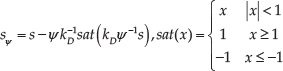
When the upper bound of torque error caused by kinetic modelling and disturbance is set at ψ, then we have:

Calculated by Lagrange dynamic equations, we can obtain the unknown parameters to be estimated as a vector:
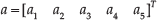
where


The augmented error can now be defined as:

Here,
Through feedback decoupling linearization, the dynamics model can be expressed as below:
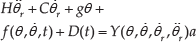
If

Control law Tu consists of the dynamic feedforward term
As such, apply the adaptive parameter estimation update laws:

where
Parameter update laws
Consider the following Lyapunov function:
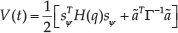
then

substituting (8) into (12):

According to Barbalat theory [25], the global stability and tracking error convergence of the adaptive control system can be proven by Equation (13). The control system considers the load as a part of the robot, thereby estimating the load mass to calculate the torque of the joint. Here, the estimated parameters
3.2. Introduction of KF state estimation
An adaptive compliant position control of a robotic leg has been implemented. However, the update rate of adaptive estimation parameter Γ is given empirically; therefore, if it is set too large, the stability margin of the system will decrease while, if it is too small, it will be too slow to update the parameters and the capability of real-time performance will decline. Meanwhile, Γ cannot be adjusted automatically because the load changes require a long adaptation time.
KF predicts errors and calibrates estimates by a non-linear system and observation. It can overcome many effects of external uncertain factors. With regard to the changed loads of a robotic leg as one of the uncertainties, the KF state estimator is added to an adaptive SEA position control. Combined with observed value and state prediction, optimal value will be estimated from the current state. It makes the parameter update rate vary according to the load change state and improves the adaptation of the parameter estimation rate.
Take the adaptive estimated parameters

where Rt is the uncertainty of motion. Given the coupling of KF state variables, it cannot be regarded as an independent state variable to estimate directly, otherwise it would mismatch the KF state estimation with an adaptive parameter update, even in the opposite direction. The changes in the load will be reflected on several dynamics and independent physical parameters,
such as
By regarding the controller output torque as the actual observed data, and the output of the adaptive feedforward term as observed prediction according to the current state, the observation equation is:

where Qt is the uncertainty of observation. The error between observation and prediction is
Due to the contradictions in anti-disturbance and convergence rates between the motion model and observations model with constant variance, an adaptive method for determining
Uncertainty about the observation model is determined by measuring the noise of the control function. Due to the frequency band of the controller output being far away from the noise, noise generated from the high-frequency component of the controller through a rapid Fourier transformation determines Qt. Uncertainty of the motion model is determined by the error between the actual output of the controller and the adaptive feedforward item. The uncertainty of the motion model Rt can be represented by decoupling the output calibration term from the state estimation error
Using the KF equations, the optimal state estimation can be derived as:

Here,

Compared with the update rate of an adaptive controller after dealing with a dead zone, the update rate of an estimated parameter can be improved by constant to real-time adjustment based on the confidence of the motion model and observation model; the overall control system block diagram is shown in Figure 4.

A simplified model of a 2-DOF articulated leg
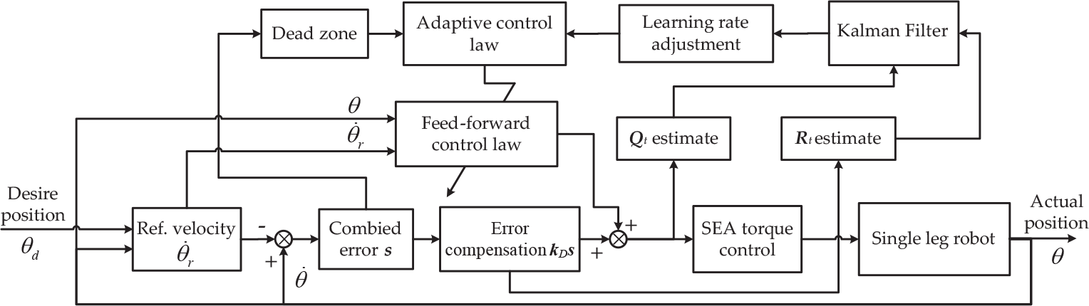
The diagram of adaptive control within a KF framework
If the load of the robot remains unchanged, the feedforward convergence value of parameter estimation is sufficient to provide the input of a controller and will not appear as a significant error. Meanwhile, the uncertainty of the kinematic equation Rt will reduce, such that the system becomes more dependent on the motion model and, thus, the update rate slows down. Moreover, the lower update rate and KF curb the effects of transient disturbances and improve the robustness of the system. If the load experiences sudden change, the parameter estimated value is impossible to meet the real demands of adaptive feedforward, and in turn the deviation of position appears. In this case, uncertainty Qt will reduce while Rt increases, with the control system becoming more dependent on the observation model. By increasing the update rate greatly, the adaptive feedforward control term will get closer to the real dynamics of an SEA-based robot in a shorter time, in order to satisfy the purpose of control.
4. Experimental Results
4.1. Experiment set-up
In respect of the mechanical design, our robot is composed of three linkages: thigh, shank and body. Two articulated SEA joints are equipped with a knee and a hip joint, while a passive joint is mounted on the body to constrain the motion in the sagittal plane. An SEA joint, due to the elastic element embedded into it, significant reduces the response bandwidth compared with a traditional rigid joint. In fact, humans have a similar bandwidth in their joints with a slightly larger range of movement, at 10Hz, for walking, running and crawling. In order to maximize the benefit of fast response and low energy loss, the CoG of the whole robot is designed to be close to the axis of the hip joint, while a parallel four-bar linkage mechanism is employed for the transmission motion of knee, which requires the knee motor to be placed close to the body. This design also brings with it an additional benefit of convenience in being able to adjust the knee joint's stiffness by simply replacing the outer springs; however, we do not use this function in our study. A carbon fibre tube is installed on the body with an extra load at both ends in order to increase the inertia ratio between body and leg. In this paper, an extra load was installed on the foot. The structure of the single-leg robot is shown in Figure 3, while a photograph of the actual leg robot, Tigger, is shown in Figure 5.

Platform of the SEA-based single-leg robot Tigger
In respect of the electrical design, two identical 200W 4Pole Maxon motors combined with 120:1 CSG harmonic drivers are used in both the knee and hip joints. Each joint is equipped with two 18-bit absolute encoders to measure the deformation of the spring. Distributed circuit boards are inscribed on the ARM processors for controlling each motor of the joint independently, in order to reduce the burden of the CAN bandwidth and receive the planning data from the PC controller through a CAN bus. An MTi-100 IMU is installed at the centre of the body to measure its posture by USB, while a switch sensor is installed at the end of the foot for judging whether the foot touches the ground or not, which will be used for the hopping experiments.
Physical parameters of the single-leg robot

4.2. Experimental results
Zero-torque control mode plays an important role in legged-robot locomotion as a special case of torque control. This is an important characteristic of an SEA joint because it makes it possible for the joint to work in either a compliant active or passive pattern mode. Especially when it works in the passive mode, the joint can work as a natural pendulum with a little mechanical damping due to its gravity or external thrust. This mode may be used for passive locomotion or energy storage in future. The curves are shown in Figure 6.

Zero-torque control in the hip and knee joints
According to Figure 6, it can be seen that the actual torque oscillated around zero. Due to the limitation of the control period cycle and motor response time, the output cannot follow the desired zero-torque absolutely. But we can find that the knee joint has a better tracking performance than the hip one, because the knee has a lower spring elasticity, which not only increases the flexibity of the joint itself, but reduces the response time requirements of the motor.
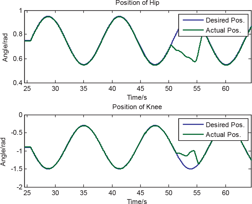
In the position control experiment, adaptive position control with and without KF has been compared, as shown in Figures 7 and 8. It can be seen that control with KF needs less time to track the desired position than control without KF. Due to the inaccuracy of the adaptive parameter estimation at the beginning, some shocks occur in a short time due to the adaptive position control. Once the estimated parameter converges, good tracking effects appear.

Hip position control without and with KF

Knee position control without and with KF
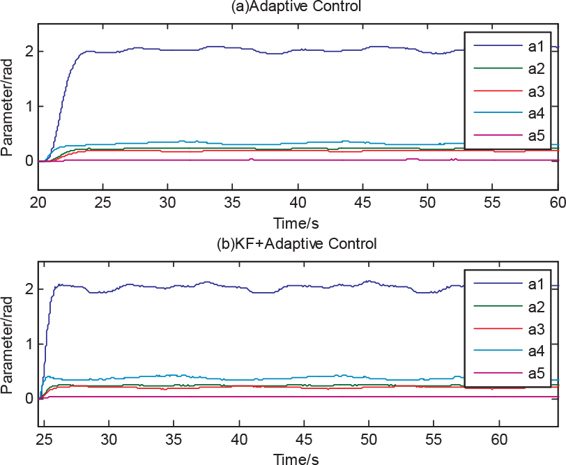
The parameter convergence rate of control method with and without KF is presented in Figure 9. As we can see, at the same initial parameters, after adding the sudden load, the former parameter convergence takes about four seconds, while the latter takes only two seconds and the convergence rate increases by about 50%.
Comparison of convergence rates without and with KF
Figure 9 shows the tracking performance of adaptive control with KF while the load changed. This method maintains high precision in tracking performance.
Compliance and disturbance rejection were tested by artificially induced disturbance while SEA joints were in position-tracking mode. As seen in Figure 10, the adaptive compliant control system has a good performance in terms of disturbance rejection and maintains a high level of stability. This shows that the robotic leg continues to deal with the disturbance rather than hurting like a human or damaging the motor with a path constraint. The locomotion of the single-leg robot immediately recovers to an accurate position-tracking after release from the disturbance without switching to any control mode. The compliant SEA-based robot, therefore, has the capabilities for precise position-tracking and security interaction in complex and unknown environments.
Disturbance resistance and compliance test
5. Conclusion
In this paper, an adaptive compliant position control method with KF is proposed. The main advantages of this method are as follows: (1) based on the dynamic model of the single leg, the adaptive control law implements compliance position control and guarantees operational safety; (2) introducing a stochastic model can effectively counterbalance the effect of disturbance and improve the robustness of the robot system; and (3) treating KF as part of the adaptive learning rate improves the convergence rate of an adaptive parameter in response to rapid load change. The experimental results show us that the methods proposed in this paper can provide a good position-tracking, disturbance-rejection and flexible interactions while operating in complex environments. It serves as a strong foundation for our future work in pursuit of more automated and natural locomotion of humanoid robots, quadruped robots and manipulators.
Footnotes
6. Acknowledgements
This research is based upon work supported in part by the National Nature Science Foundation of China (514054530, 61473258, 61273340) and the Public Welfare Technology Application Research Plan of Zhejiang (2016C33G2010137).