
Abstract
A flexible snake robot has better navigation ability compare with the existing electrical motor-based rigid snake robot, due to its excellent bending capability during navigation inside a narrow maze. This paper discusses the modelling, simulation and experiment of a flexible snake robot. The modelling consists of the kinematic analysis and the dynamic analysis of the snake robot. A platform based on the Incompletely Restrained Positioning Mechanism (IRPM) is proposed, which uses the external force provided by a compliant flexible beam in each of the actuators. The compliant central column allows the configuration to achieve three degrees of freedom (3DOFs) with three tendons. The proposed flexible snake robot has been built using smart material, such as electroactive polymers (EAPs), which can be activated by applying power to it. Finally, the physical prototype of the snake robot has been built. An experiment has been performed in order to justify the proposed model.
Introduction
The flexible snake robot is a novel idea in the field of robotics. The traditional robotics concepts are modified in this work, in which each of the links acts as a three-dimensional (3D) joint. Each of the single links is able to perform a 3D motion. The single actuator is, in fact, a special version of a parallel platform. It is also known as a small-scale tendon-driven flexible actuator [1]. Much of the research on tendon-driven Stewart platforms is devoted either to the Completely Restrained Positioning Mechanism (CRPM) or to one particular type of the IRPM, where the external force is provided by the gravitational pull on the platform, such as in cable-suspended Stewart platforms. The actuator developed here is based on the IRPM. It uses a central compliant member connecting two parallel platforms, which are connected by three active tendons placed at the outer edges of the platforms. The tendons are parallel to the central compliant member; meanwhile, none of the tendons is activated. The compliant central column allows the configuration to achieve 3 DOFs with the different activation (force) of the three tendons. Each of the tendons is built using EAP material. EAPs are activated due to the application of electrical power.
State of the Art
Since 1928, parallel mechanisms have been used in research to develop new kinds of robot [2]. Perhaps the most well-known and widely used of these parallel robots is the Stewart platform, which gained prominence due to its use in flight simulators. The traditional Stewart platform, which is actuated by pistons attached to the base and the platform by universal or ball-and-socket joints, has given rise to other variations of such platforms. Of these variants, those of primary interest use compliant members, while those of secondary interest use tendon or cable actuation. The idea behind the constraining central leg introduces another method for configuring the Stewart platform. In the area of tendon-driven or cable-suspended platforms, a few configurations have been proposed. The best known cable-suspended planar parallel robots are the RoboCranes, developed at NIST [3, 4], where the end-effector sits on a platform suspended from a fixed frame using six cables to achieve 6DOFs. Issues regarding the workspace and design of general cable-based planar robots were addressed by Fattah and Agrawal [5], in which the platform was not only suspended, it was also constrained by cable from above and below. A tendon can only bear tension forces; to ensure that the tendons are always under tension, different solutions are advised. Sometimes the end-effector is suspended from the tendons, which is ensured by use of the gravity force or any other passive force against the moving platform [6]. Another more applicable solution for high acceleration applications is to use redundant actuators, as well as resolve the redundancy to ensure positive tension in all the tendons. This can be performed in a fully–constrained or over–constrained moving platform [7], although this presents more difficulties for analysing the geometry [8] or force of the possible workspace [9, 10]. An elastic material-based tendon connected to a motor was introduced to create a miniature actuator for high power and torque generation [11]. The elastic material used in that actuator was a passive actuator. A tendon-based humanoid hand was fabricated by the University of Bologna (UB) [12]. Metallic string was used in this prototype for actuating the fingers. A detailed analysis of tendon-based actuator activity was presented in this work [13]. A new kinematic model was introduced for the spring loading and concentric nature of the new robotic cable design [14]. The new modified kinematic formulation for 2D and 3D operations is the other significant contribution made in relation to the modelling of long and thin continuum cable-like robots.
EAPs perform deflection in response to an electric activation as a result of the mobility of hydrated cations inside the polymer network. EAPs are sandwiched between two electrodes. The actuation mechanism consists of applying an electric field between the electrodes. This field produces a solvent flux to the hydrated cations and free water through the cathodes. This solvent flux creates an electro-osmotic differential pressure resulting in a bending motion towards the anode side of an EAP. The use of EAPs is being extended to several different applications, which are: linear actuators [15], 3D actuators [16], microgrippers [17], exoskeleton human joints [18], wing flaps [19] and biomedical applications [20].
Modelling of a Smart Actuator
A smart material-based actuator model is proposed here in order to develop a flexible manipulator. An investigation into the kinematic feasibility of the actuator is taken into account in this research. Considering the advantages of the compliant members and those of the tendon-actuated planar parallel mechanisms, a design is suggested here, in which both the compliant aspect, as well as the tendon actuation, might be used to develop simple miniature Stewart platforms, which could be used as linkable modules in a locomotion device.
Proposed Model
In this application, however, due to the nature of the 3DOF device, the position actually determines the orientation, rather than the exact Cartesian position of the end-effector. The interest in this situation is the angular displacement of the upper platform with respect to the lower one. The desired output of the system, therefore, is the angle between the upper and lower platforms. When linked to one after another in such a module, it is the angle that will allow the chain of platforms to bend in a different formation to achieve locomotion. For the output, therefore, three generalized coordinates are selected. The first is the height of the central column, h: effectively, a translation along the z-axis, which can be compressed by applying tension on all three tendons, as shown in Fig. 1. The second and third coordinates are the angles formed by the upper platform and the lower platform about the x- and y-axes. Rather than composing this angle from rotations around x and y, spherical-like coordinates are adopted, as shown in Fig. 2. That is, in the x-y plane, angle θ denotes the anticlockwise angle measured from the positive x-axis. The projection of the bent central column onto the x-y plane is, therefore, assigned the variable d. As such, the second angle φ denotes the angle between the plane of the upper platform and d. This angle differs from the spherical coordinate equivalent, as the vertex of this angle is not at the origin. In fact, the vertex of the angle moves further away from the origin as the angle decreases, and comes closer as it increases.
Given the coordinates of h, θ, and φ in Fig. 2, the Cartesian coordinates x, y and z can be determined, which are then used to calculate the length of the three cables. Before performing the inverse kinematics, assumptions are made in order to simplify the calculations. The assumption made here is that, for any desired position of the end-effector, the central column shall always bend in order to assume a circular arc with a radius of curvature R. Although the column may not necessarily form a circular arc, this assumption is made as an approximation. The validity of this assumption shall be investigated upon constructing a physical model.
We can now derive the kinematic analysis for n number of links in order to form a snake robot, where each of the links contains three tendons. In turn, we can demonstrate the snake configuration with n number of links.
The n number of upper platform coordinates (x i , y i , z i ) can be determined by:

where the initial coordinate lies at the origin, such as x0=0, y0=0 and z0=0.
In equation (1), i=1, 2, 3,…., n, which indicates the number of upper platforms, the radius of curvature of central column R will remain the same for all circular arcs.

Geometric figure of a single link

Geometric structure of the proposed snake robot
According to equation (2), we can determine the initial positions of the three coordinates of the tendons for the lower and upper platform as follows:


In equations (2) and (3), i-1 refers to 0 because i = 1,…, n.
For n number of curvature links, the lengths for the three tendons of each links can be determined by:

To determine the vector from the lower platform to the upper platform for all three links of n links, the following applies:


Now, the distance vector between the two coordinates of the central column for n number of links becomes:

The i th link pitch and the yaw angles can be determined by using the coordinate's values of θ and φ i . Thus, α i as the rotation about the x-axis and β i as the rotation about the y-axis for i th link become:

Now, the vectors of the transformed position of the upper platform for i th link, using α i and β i angles, can be calculated by:


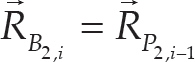
After the transformation of the upper platform of the link, the position vector of the upper platform now becomes the new position vector for the lower platform of the next link. Thus, we can write:


Finally, all the tendons' length of the i th link can be determined in any position and orientation by:

Similarly, we can obtain the other two tendons' length of the i th link from the following equations:
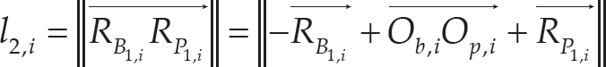

Fig. 3 shows the simulation of all six relative upper platforms for each of the link angles of the robot. A modified serpentine motion is simulated for flexible motion of a snake robot as shown in Fig. 4. Fig. 5 shows the steps of modified serpentine motion which allow the snake robot to move forward.

Change of relative angles in the upper platform, with time

Modified serpentine motion for the snake robot: (a) single direction, (b) multiple direction and (c) moveable workspace
The Euler–Lagrange method is used in the modelling of the snake robot. The simplified version of the Euler–Lagrange equation is presented by:

where qi represents the generalized coordinates, Qi is the generalized force corresponding to qi, M is the inertia matrix, Ci is the centrifugal and the Coriolis matrix, U is the potential energy and fc is Rayleigh's dissipation function.

Steps of the modified serpentine movement

Illustration of single link actuator
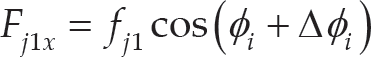
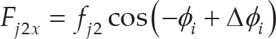
Fig. 6 shows the forces fj1 and fj2, which are applied by the actuator (with respect to the spine) located between ribs AB and CD. Based on Fig. 6, the following relations are valid for force fj1, fj2 components along the x- and y-axes.


Solid Model of the Actuator
The actuator of a single link contains two bases, three EAP tendons and a spring-like soft material, as shown in Fig. 7. In Fig. 8, the top view of the actuator is shown, in which the three tendons are able to perform a 3DOFs motion by the linearly tension-compression actuation of the tendons.

Perspective view of the 3D solid model of the actuator
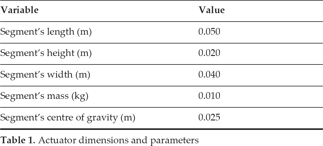
The EAP-based flexible actuator used in this research is shown in Fig. 9. It consists of a flexible central body, while three EAP tendons are attached for the tendon-driven Stewart platform's actuator. The actuator is powered externally. The single actuator's dimension and parameters are given in Table 1.

Top view of the actuator
Actuator dimensions and parameters
In order to provide safety to the user, the EAP actuator was mounted inside a transparent rubber pocket. Three EAP tendons were attached between two platforms. This actuator performed the 3DOFs motion.

Prototype of the EAP-based flexible actuator
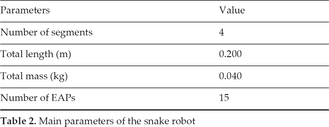
The schematics structure of the proposed prototype of the snake robot is illustrated in Fig. 10. In general, the robot will have five rigid bases connecting four EAP segments. The flexible snake robot is partitioned into four links. Each link consists of an EAP actuator and two rigid bases connected to both terminals of the EAP. From the figure, it is clear that each segment of the robot consists of different parts, which are assembled together. The link rotation axis for each segment is at the middle of the two rigid bases. An elastic material is connected with the underneath of all rigid bases of the snake robot, as shown in Fig. 10. The elastic material is used here for the scale of the robot, which is enabling the snake robot to move forward. More friction can be obtained from this elastic material due to the faster movement of the robot. Table 2 shows the brief specifications of the proposed snake robot's model.

Side view of the proposed prototype
Main parameters of the snake robot
Taking into consideration the results of characterization and manufacturing limitations, it was concluded that each of the actuators in the flexible snake robot prototype should have dimensions of 30mmx3mmx1mm. Four independently-actuated individual EAPs are used to construct the snake robot. This number of EAPs is sufficient to generate a sinuous body undulation. The robot is made from a single gold-plated EAP. It has a weight of 40mg. Using these EAPs, it was further determined that the applied voltage required to achieve acceptable bending should be in the range of 3.5–6V for gold-plated ones. A four-segment gold-plated EAP snake robot is shown in Fig. 11. Obtaining good electrical contacts poses another technical problem in EAP applications, especially on such a small scale. Due to the anti-adherent properties of EAPs, conductive glues and cold soldering methods cannot be used to connect a wire to a gold-plated EAP surface, except when using the clamp system.

Four-segment snake robot made from an EAP
Fig. 12 shows the experimental apparatus for the snake robot control system. Body shapes are obtained from a high resolution camera connected to the computer.
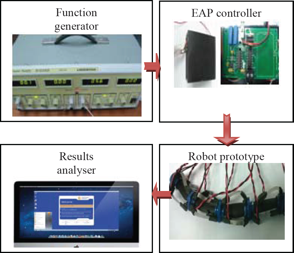
Experimental apparatus: each IPMC segment is driven separately by a D/A and an amplifier channel
An experiment was conducted after successfully simulating the proposed model. The alignment of the EAP actuator is fixed at 0, 0 to the x-axis. Room temperature was set for the experiment. MATLAB was used to perform the input-output parameters of the single EAP actuator. The amplified signal generator controller was used to perform this operation. The EAP actuator's position was monitored by the Kinect video system, which allows for 32 frames per second. The operated frequency, as shown in Fig. 13, was used in the controller for large deformation.
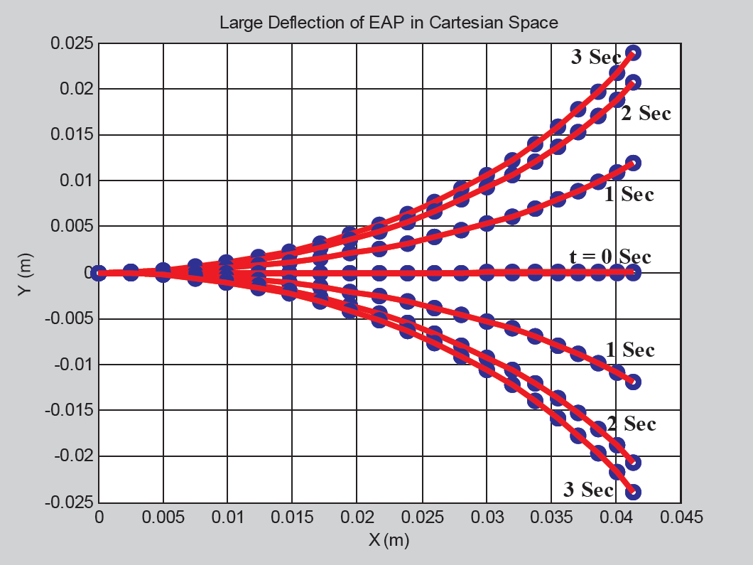
In the actuation system of a snake actuator, a 30 mm long, 5mm wide and 1mm thick EAP is developed for the actuation because the primary concern in the design is actuation and the bending response. However, the actuation system should be able to produce a desired deflecting angle for a successful bending device. The simulation result of flexible bending actuation system is shown in Fig. 14 while the experimental result of bending actuation of a single EAP is shown in Fig. 15. This generated actuation system is applied to the attached rigid frame system. By attaching the actuator in series configuration, it may perform a sinusoidal wave to mimic snake locomotion.
Finally, a series of implementation and verification of the EAP actuator has been performed for 60 seconds. Fig. 16 shows the bending performance of the EAP, in which each snap is depicted for every one second. In Fig. 16, a large deflection is observed for the EAP actuator, which is compliant with the snake robot actuation system.

Frequency operated in the controller

Simulated results for the EAP when 5V are applied uniformly
Experimental results for the EAP when 5V are applied uniformly

Actuation of the EAP actuator for the validation of the simulation model
An experiment was conducted for force measurement of the EAP actuator in consideration of the constraints at both ends. A metal coin with a weight of 6gm was affixed to one end of the 1 mm thick gold-plated EAP. The other end of the EAP was fixed by a clamp, as shown in Fig. 17. The clamp was connected to the controller board. The controller board supplied a minimum of 3.5V to a maximum of 6V for EAP activation. Fig. 18 shows a pictorial view of 10 sequences of EAP bending as a result of carrying the load. From this experiment, we achieved a 60mN force from the EAP actuator. Fig. 19 shows the experimental results for different values of forces generated by the EAP by varying the input voltage.

Experimental set-up for the load-handling properties of the EAP
The force profile for each link actuator is shown in Figs. 20 (a) to (d). The maximum force value observed is 45 mN, which was found at the first link actuator.

Actuation sequences for the EAP actuator in order to perform bending with a load on one end

Generated force by the EAP actuator at the tip, according to differently applied voltages
The control voltage applied to each segment is obtained from the controller in order to generate both positive and negative voltage signals. The program can generate a variety of output waveforms for testing purposes. Initial experiments are performed in order to test the response of the actuator and its ability to produce a sinusoidal undulation. Specifically, the sinusoidal waves applied to the robot have a wavelength of one body length and are applied with equal phase lags to contiguous segments in order to achieve a travelling wave at the desired frequency. This long activation time also allows the EAP to produce greater bending. Typical body shapes are shown in Fig. 21.

Force profile of the snake robot: (a) first link, (b) second link, (c) third link and (d) fourth link

Two frames from video footage of a controlled EAP robot, showing typical snake robot shapes
A flexible snake robot has been demonstrated in this paper. The design and kinematic analysis of the actuator has been demonstrated in this work. In particular, this investigation focuses on the angular deflection of the upper platform with respect to the lower platform. The modelling investigation demonstrated the feasibility of the pseudo-rigid-body model in modelling compliant mechanisms, as well as illustrated how a simple modular compliant structure could be developed, at least at the macro level. When it comes to the specific EAP actuator design presented in this research, final studies have been conducted regarding the structure. Such studies would only be truly conclusive for snake actuator mechanisms. Furthermore, a complete snake robot bending actuation experiment has been demonstrated in this paper.