
Abstract
This article proposes a novel gait on cylinders for a snake robot as well as arboreal concertina locomotion gait, including the generation method. The gait on the cylinder of a snake robot is a kind of spatial motion planning that is difficult in manual design. In this article, a planar gait of a snake robot is first constructed, followed by cylindrical gait via a transformation mechanism. In addition, a gait generating scheme of arboreal concertina locomotion gait of snake robots on cylinders is constructed and verified via a simulation platform. Such gait makes advantages on cylindrical motion capability of snake robots and the proposed generation approach for gait construction can be promoted to other cylindrical gaits, reducing design difficulty.
Introduction
After millions of years of revolution, animals achieved amazing adaptability which inspired researchers to create new inventions. Snakes are one of the most versatile animals in nature; it can move in diverse environments, such as grasslands, deserts, rivers, and trees. As being simple though, the elongated bodies of snakes enable free movement within various environments by utilizing different gaits.
The artificial structure composed of rods or pipes can be found everywhere in our daily life, and related discovery still poses a challenge in the design and application of robots. Because of its special body shape, snake robot has great advantages in exploring rod or pipe structure. Hatton and Choset proposed the helix rolling gait of pole climbing based on the method of annealed chain fitting and Keyframe wave extraction (ACFKWE). 1 Kamegawa et al. realized the climbing motion of snake robots with passive wheels on cylinders by analyzing the continuum model of snake robots. 2 Melo et al. studied the relationship between climbing speed and geometry of the robot body and cylinders when snake robots climb on a horizontal cylinder. 3 Enner et al. proposed an estimation method for position and posture of snake robots based on Extended Kalman Filter. 4 Based on this estimation method, Rollinson and Choset realized the compliant control method, which provides snake robots the abilities of self-adaption of cylinder diameter and blocked stopping. 5
Above climbing gaits of snake robots on cylinders were proposed from engineers’ perspectives. The snake robot surrounds the cylinder, which restricts the robot, allowing it to only move on a pole rather than a more complicated structure, such as a truss or a tree with many branches. There are two main gaits of snake moving in trees: arboreal lateral undulation locomotion (ALUL) and arboreal concertina locomotion (ACL). 6 ALUL gait has a higher speed of movement but is limited to a driving force add-in due to branches. ACL gait has a better adaptability to environment, including a simple rod and a complex truss structure.
The difficulty of designing gaits on cylinders is the contact surface of snake robots from the horizontal plane onto a curved surface, making the entire snake robot space configuration unimaginable. Currently, gaits generation method can be divided into four categories, sine-based method, model-based method, central pattern generation-based (CPG-based) method, and curve-based method.
Sine-based method uses sine-based function as joint reference angle for snake robots. Based on the observation of motion of snakes on grounds, Hirose accomplished lateral undulation gait with sine functions on the snake robot assembling passive wheels. 7 By setting different sine functions as reference angle for pitch and yaw joints, and adjusting the amplitude, frequency, and phase difference of those sine functions, different gaits of snake robots can be obtained, including side-winding gait, 8,9 rectilinear gait, 10,11 and helix rolling gait. 1 The advantages of sine-based method are easy to achieve and there is a strong correlation between parameters of sine function and the motion performance.
Model-based method can improve the motion performance with kinematics and dynamics analysis of robots. Hicks and Ito proposed an optimal control strategy for snake robots based on a series of reduced dynamics equations of robot system. 12 To realize the obstacle-aided motion without wheels, Transeth et al. developed a hybrid dynamic system for snake robots to simultaneously deal with the contact force from obstacles and friction force using set-value force laws. 13 The limitations of model-based method are the dependency on accurate model and the computation complexity increasing with the number of joints.
CPG-based method uses a special neural network or coupled oscillators as gaits generators for snake robots. One interesting feature of this method is the ease of incorporating sensory feedback. Using sensory information, Crespi and Ijspeert realized the amphibious motion of snake robots in water and land and adjusted swing amplitude to obtain the optimal moving speed by Powell’s method. 14 Tang et al. constructed multi-phase CPG to realize a variety of gaits and designed the optimal gaits selection strategy based on the speed sensory signal. 15 CPG-based method has great potential in improving the environmental adaptability, but its model design and parameter adjustment still remain a challenge.
Curve-based method is different from abovementioned gaits generation methods. No matter what method used, the sine-based, model-based, or CPG-based method, the control objects are the joint angle or joint torque of snake robots. Curve-based method designs the body curve of snake robots and the mechanism for converting the body curve to the joint angle. Hatton and Choset proposed the approach of ACFKWE. 1 In this approach, the motion is decomposed into a series of curves, and then the control function of the joint angle is extracted. Liljebäck et al. proposed a control framework to solve the problem of shape control in obstacle-aided motion. 16 This control framework sets the contact points between the snake robot and obstacle as shape control points (SCP) and then connects these points with Bézier curves. The control function joint angle is obtained by progressing a virtual snake along the body curve. This control framework can also generate lateral undulation gait and concertina gait on ground.
For generation of ACL gait on cylinders, the sine-based, model-based, and CPG-based methods cannot guarantee the shape of snake robots to meet the gait requirements. Liljebäck’s control framework is not suitable for generating ACL gait, because the Bézier curve is a plane curve. The approach of ACFKWE is a possible solution but is suffered from complexity. Therefore, in this article, a novel gait design method for ACL is proposed. The basic idea is to design concertina locomotion (CL) gaits on horizontal planes first and then to translate gaits on planes into ACL gaits on cylinders by transformation mechanism. The process of design CL gaits is similar to the method of ACFKWE. It is easy to build CL gaits since they occur on plane. By coordinate transformation, the mechanism lies in transformation of control functions of joint angles of CL gaits on planes into the control functions of joint angles of ACL gaits on cylinders. The process of coordinate transformation mainly refers to the kinematics of manipulators. 17 Then, in order to guarantee the feasibility of the proposed ACL gait, the kinematics and dynamics of the gait are analyzed to avoid the geometric interference and slipping from cylinders. Most of the researches about the gaits of snake robots involve kinematics and dynamics analysis, partly for the motion of the snake robots on the plane 18,19 and partly for the motion on the cylinder. 4,5 In this article, the force analysis of snake robots winding the cylinder is analyzed to obtain the optimization design parameters of ACL gait.
The article is organized as follows. “Design of CL gait on a plane” section analyzes the CL gait of snake robots on horizontal planes. “Planar–cylindrical gaits transformation mechanism” section presents the transformation mechanism of CL gait on a plane to ACL gait on a cylinder. “Gaits analysis and parameter determination” section introduces the parameters analysis of ACL gait based on kinematic and dynamic models of snake robots. “The design scheme of ACL gait of snake robots” section provides the complete design scheme of ACL gait and its verification with simulation platform. Finally, the last section contains the conclusion and future work.
Design of CL gait on a plane
It is much simpler to plan CL gaits on the plane than to directly plan ACL gaits of snake robots on cylinders. Based on two different winding types, this section designs two different CL gaits. The process of building CL gaits is similar to the method of ACFKWE.
There are two winding types for snake robots on cylinder: H-type winding and S-type winding. In the H-type winding, snake robots wrap around the entire circumference of the cylindrical surface, while the S-type winding does not. The CL gaits of H-type winding and S-type winding are planned first on the plane, and then converted to gaits on the cylinder using a transforming mechanism introduced in “Planar–cylindrical gaits transformation mechanism” section. The sketches of H-type and S-type winding of snake robots are shown in Figure 1.

Sketches of H-type and S-type winding of snake robots: (a) H-type winding and (b) S-type winding.
The Planning of CL gait of H-type winding on a plane
The body structure of the snake robot was divided into three sections: head section, middle section, and tail section. Head section and tail section were used to affix on the body of snake robots and the length of the middle section is related to the moving distance of each movement period. The length of each link making up the snake robot is equal, so the length of each section is determined by the number of links within each section: the number within the head section nH, the number within the middle section nM, and the number within the tail section nT. The larger the value of nH and nT, the safer the snake robot is during climbing. The larger the value of nM, the longer the moving distance within each period.
There are two types of links; they are segment links and transient links. The orientation of segment links in each segment remained consistent. The transient links connected the adjacent segment links and the orientation of segment links was different from the segment links at the start of every motion period. As shown in Figure 2, solid bar represents segment links and blank bar illustrates transient links.
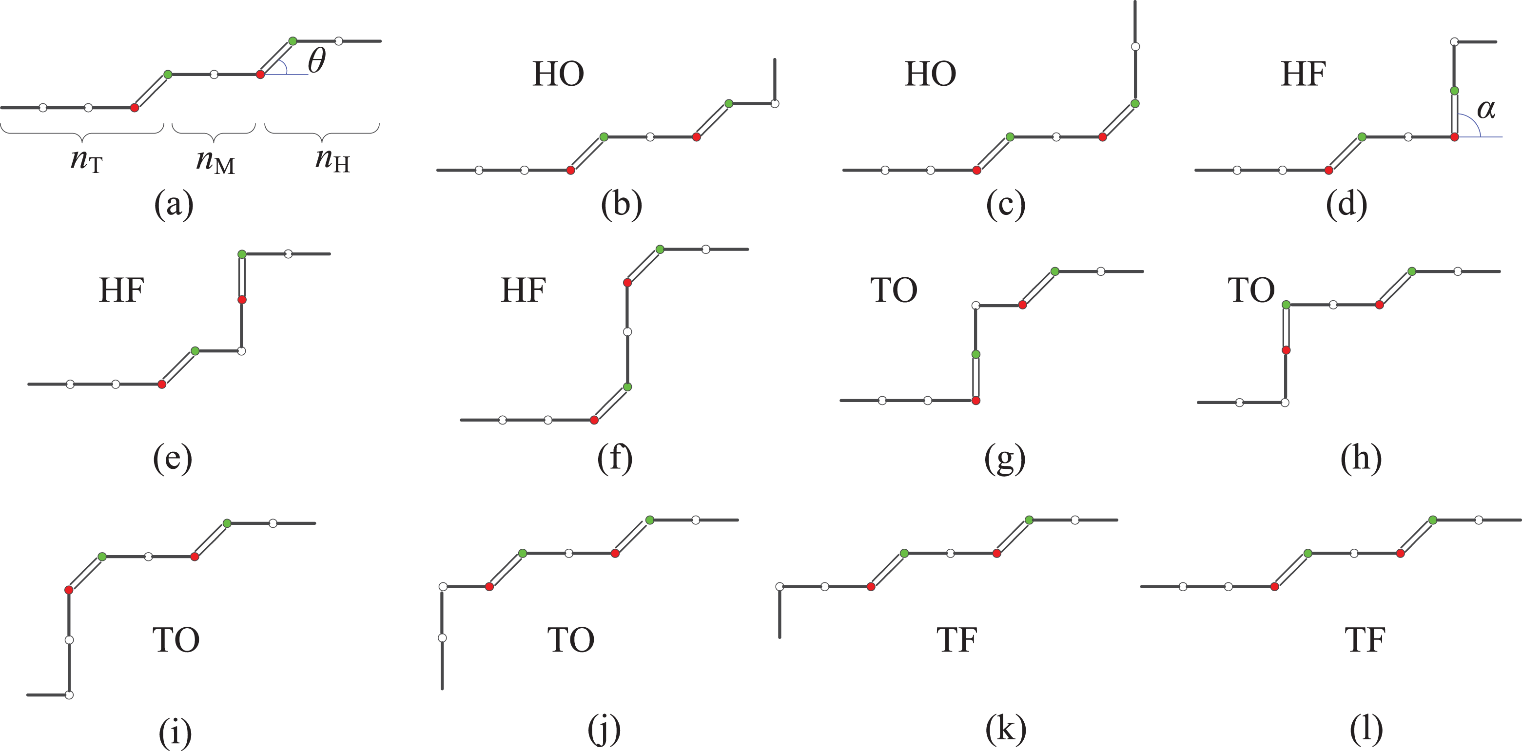
H-type winding gait planning on plane.
The period of movement of snake robots is divided into four phases: head opening phase (HO), head folding phase (HF), tail opening phase (TO), and tail folding phase (TF).
As illustrated in Figures 2, steps (b) and (c) are head opening phases. The number of steps in the head opening phase is equal to nM. In this phase, the snake robot raises parts of its body to move forward. Steps (d) to (f) are head folding phases. The number of steps in the head folding phase is equal to nH. In this phase, the snake robot affixes itself with tail section and the head section moves forward. Steps (g) to (j) are tail opening phases. The number of steps of the tail opening phase is equal to nT. In this phase, the snake robot affixes itself with head section, the middle and tail sections move forward. Steps (k) and (l) are part of the tail folding phase. The number of steps in the tail folding phase is equal to nM. In this phase, the snake robot folds up the links within its tail section and finishes one period movement. If the number of links making up the snake robot is nB = nH + nM + nT, the number of steps in each movement period is nn = nH + 2nM + nT.
There are three types of joints: the normal joint (NJ), which is illustrated with blank circles in Figure 2; the transition-start joint (TSJ), which is presented with green circles in Figure 2; and transition-end joint (TEJ), which is shown with red circles in Figure 2.
The angle curve of ith NJ is presented in Figure 3(a). The joint moves the links forward at the peak of the curve and returns to the original direction at the trough of the curve. Figure 3(b) and (c) shows the angle curve of ith TSJ and TEJ. The behaviors of TSJ and TEJ are similar to NJ. However, the initial angle of TSJ and TEJ are not zero, because of this, the peak and trough of the curve of TSJ and TEJ are not symmetric.
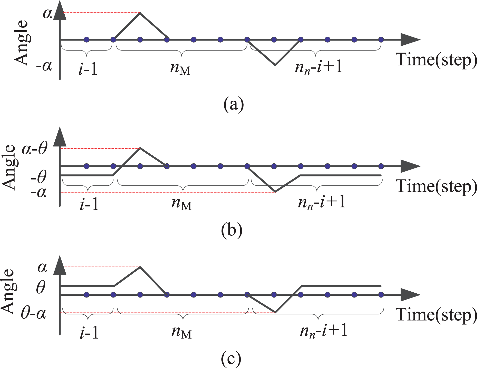
The ith joint angle curve of H-type winding gait in one period.
The anticlockwise direction is defined as positive. The right end of the snake robot is defined as the head, so the angle is positive when the ith joint moves in the first half period. If the left end of the snake robot is its head, the angle is negative.
The planning of CL gait of S-type winding on a plane
In the process of S-type winding gait, the snake robot curves its body and grasps the cylinder like a hand. The links making up the snake robots are divided into two categories: segment links and transition links. Segment links are used to secure the robot and transition links are added to reduce the angle of adjacent links. Each segment has ns links. In Figure 4, segment links are illustrated as solid bars and transition links are illustrated as blank bars.

S-type winding gait planning on plane.
The body of the snake robot body is also divided into three sections: head section, middle section, and tail section. The function of each section is similar to that of the H-type winding gait. The head section has nHs segments, the middle section has nMs segments, and the tail section has nTs segments. There is one transition link between two adjacent segments; therefore, there are ntl(ntl = nHs + nMs + nTs − 1) transition links.
The period of S-type winding gait also has four phases: head opening phase (HO), head folding phase (HF), tail opening phase (TO), and tail folding phase (TF). The function of each phase is comparable to the H-type winding gait. The difference lies in the fact that S-type type winding gait has two head folding directions corresponding to the position of the head section at the last step of the head opening phase. If nms is an odd number, the head section folds toward the opposite direction compared to the initial pose. If nms is an even number, the head section folds into the same direction compared to the initial pose.
There are three types of joints, normal joints (NJ), left transition joints (LTJ), and right transition joints (RTJ). As shown in Figure 4(a), NJs are presented with blank circles, LTJs are expressed as green circles, and RTJs are shown as red circles.
In S-type winding gait, the snake robot folds its body to make an S shape. The head of the snake robot alternately points toward the left or right or the same direction, which is determined whether the
Figure 5(a) shows the angle curve of ith NJ of S-type winding gait, which is similar to H-type winding gait. But there are two different curves controlled by the parity of nM. When nM is even, the joint curve of NJ is red; it has one peak and one trough in one period. When nM is odd, the joint curve of NJ is green. It has two peaks and two troughs in one period. The Figure 5(b) and (c) illustrates the joint curve of ith LTJ and RTJ. They are not similar to the curve of NJ. They have a nonzero initial joint angle and do not have an independent peak or trough within one period.

The ith joint angle curve of S-type winding gait in one period.
The total number of all segment links is
It should be clearly noted that the change of joint angle is illustrated as linear in Figures 3 and 5 but the change process of the angle is arbitrary even though the start and stop angles are determined.
Planar–cylindrical gaits transformation mechanism
The section “Design of CL gait on a plane” illustrates the gait planning of snake robots on a plane. This section presents how to transform the reference joint angles of the snake robot from a plane to a cylinder. This includes three parts: first part illustrates the attitude of every link of snake robot on cylinder; second part gives the revolute angle of each joint on the snake robot; and third part presents the constraints of angle velocity of each joint for avoiding the slipping of the snake robots along the direction of a cylinder axis.
The process of establishing the transformation mechanism mainly uses coordinate transformation, which is similar to the kinematics analysis of manipulator. In section 2, joint angles of snake robot are classified into different joints, such as NJ, TSJ, and TEJ, but they are not distinguished when performing planar to cylindrical gait transformation.
In this section, all calculations are based on the assumption that every joint of the snake robot have the capability of moving in pitch and yaw directions.
Notation defining
pi means the ith vector in frame
The position of the snake robot on a cylinder
The position of links in each moment of the snake robot has been illustrated on a plane as shown in Figure 6(a). The snake robot is imagined as a curve on a paper, and then this paper is rolled as clarified in Figure 6(b). A reference The orientation of links of the snake robot: (a) links on plane and (b) links on cylinder.
Two hypotheses are premised. One is that the length of every link of the snake robot projecting on plane
Two rotation angles are defined. The first rotation angle is θhi, which represents the angle between adjacent links of the snake robot moving on a plane. The second rotation angle is θvi, which symbolizes the projection angle on the plane of
The p0 is defined along the direction of the y-axis of frame

Revolute angle of every joint of snake robots
Each joint of the snake robot has pitch and yaw degrees of freedom. The axis of pitch and yaw joints has a point of intersection oi. The point oi is also the origin of the ith local frame
The position of every link of the snake robots pi is calculated in first part; the relationship between the ith pitch joint revolute angle θpi, the ith yaw joint revolute angle θyi, and the placement of ith link pi is presented in equation (2).

Equation (2) is a recurrence formula, so

Now,
Defining the components of

The domain of

Constrains of revolute velocity of pitch and yaw joints
In the second part, the position of the snake robot has been determined, but the body of snake robot will have a sliding movement along the axis of the cylinder. This sliding motion makes the snake robot unable to hold the required position. Because of this, the components of velocity within each link of the snake robot along the z-axis of frame
The angular velocities of the ith pitch and yaw joints are

The component of velocity of each link of the snake robot along the z-axis of frame

equation (6) means the angular velocity of the ith pitch and yaw joints must be proportional. Constraints of the pitch and yaw joints’ angular velocity are practical, angular velocity being the main control parameter of most motors.
Gaits analysis and parameter determination
After the gait planning of snake robots on a cylinder, gait parameters are studied considering the geometry of cylinder, the geometry of snake robots, and the drive force of motors. Gait parameter analysis contains two aspects: kinematic analyses and dynamic analyses. Kinematic analysis checks collision between the links of the snake robot. The analysis includes the limitations of the cylinder radius, the length and radius of links of snake robots on the joint angles, and the number of links of the snake robot. Dynamic analysis assures the gaits work. On one hand, the influence of winding angle and number of winding links on fixing force is obtained with Newton–Euler equations and convex optimization. On the other hand, it analyzes the joint torques required to ensure that a snake robot can perform the ACL gait.
Kinematic analyses
First, the relationship between
Assuming the snake robot has a consistent


Snake robots winding on cylinder with one loop.
The angle between adjacent links project to plane of

Second, the relationship between angle θr and the geometry of the snake robot is explored. The maximum rotation angles of joints of snake robots θr will influence the flexibility of snake robots’ motion. It is determined by the maximum rotation angle of the motor and the body structure of snake robots. The main parameters of geometry of snake robot bodies relating to

The constrain of geometry of links of the snake robot to the revolution angle.

Third, the relationship between the value domain of angle ϕ and the parameters of snake robots is studied. In H-type winding gait, the improper choice of angle will cause interference in the snake robots body. The height occupied by the snake robot body on a cylinder is hs. It should be larger than the rising height of snake robots around the cylindrical circle h. The parameters ϕ, hs, and h are shown in Figure 9. The body of the snake robot is illustrated with a yellow band.

The sketch of geometry interference of snake robots on a cylinder.
The constraints for the angle ϕ is listed below:

Dynamic analyses
The dynamic analyses of ACL gaits focus on the condition where the snake robot winds along a cylinder with a single loop. Considering the condition of a multi-loop enhances the difficulty of dynamic analyses, losing efficient analysis results. The purpose of dynamic analyses in this article is providing a foundation for choosing a motor by providing the maximum torque demanded. Motors on most of these snake robots are designed for position control or velocity control. One just needs to estimate the torque range of motors used on snake robots. Figure 10 shows the force diagram of the snake robot winding on a cylinder with a single loop. Ni is the normal force exerted by a cylinder to the ith link of the snake robot. τi is the torque produced by the ith joint of the snake robot. If the length of links of the snake robot is equal, the attitude of the snake robot is symmetric. So, Figure 10 only illustrates the right half of the whole snake robot.
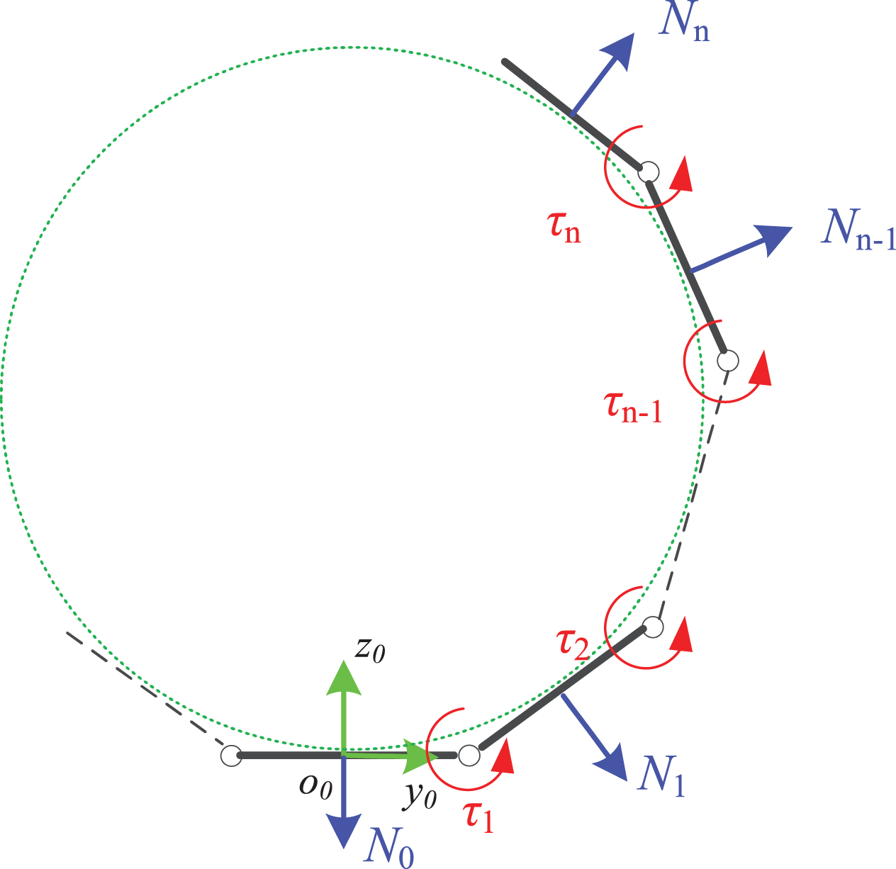
The force diagram of the snake robot winding on cylinder.
By momentum equivalence, the relationship between normal force Ni and the motor torque τi is established.
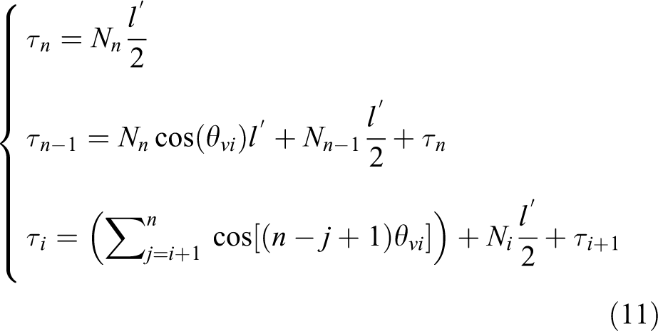
By simplifying:


There are infinite combinations of τi for the output of motors being within a domain from zero to maximum τmax. There must be a combination satisfying these two requirements: the first is resultant force of all Ni being zero, ensuring the safety of snake robots; the second is the sum of all the absolute values of Ni being maximum. Linear programming can solve this. The cost function is:

The constraints should be classified into two situations: the number of single loop links of snake robot ns is either even or odd. If ns is even, the sum of projection of all normal pressure force

If ns is odd, there is an additional force N0, its quantity is not less than zero. Compared to the even situation, constraints reduce an equation. The expression is:

The force of fixing the snake robots body to avoid falling from the cylinder is the force of friction between the robots body and the cylinder. The quantity of friction force is determined by the sum of all normal force Ni, which is represented with J. The maximum of fixing force of snake robots Fmax with different winding range and winding links can be obtained by calculating Jmax and multiplying friction coefficient μ. The minimum of winding range of the snake robot is no less than π and the number of winding links is no less than three for force balance. Figure 11 shows the relationship between the maximum of the fixing force Fmax, winding angle θc, and the number of winding links ns. The winding angle is from π to
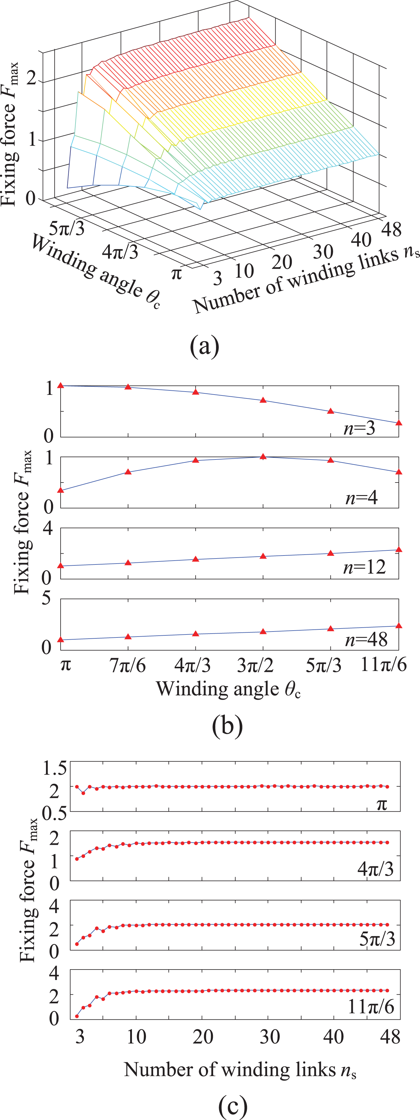
The relationship between fixing force, winding angle, and number of winding links.
As shown in Figure 11(a) and (b), the fixing force Fmax increases with winding angle θc when ns is greater than five. When ns is not greater than five, the relationship between Fmax and θc should be calculated, respectively. As presented in Figure 11(a) and (c), the fixing force Fmax increases with the number of winding links ns when θc is greater than n. The parity of ns influences the increasing trend of Fmax. When ns is greater than ten, the Fmax tends to be a constant value. This means that the greater number of ns is not helpful to the fixing force Fmax when ns is greater than ten.
The maximum torque of motors in the process of lifting the snake robot body is another factor to be considered. Based on static analysis, two cases of the motor torque of the highest requirement are studied. As shown in Figure 12, one case is where the cylinder is laid vertically and the snake robot winds around the cylinder with the head section; however, the winding angle is less than π, so the head section cannot supply the fixing force. The motor raising the body of the snake robot bares the maximum torque. This motor is named
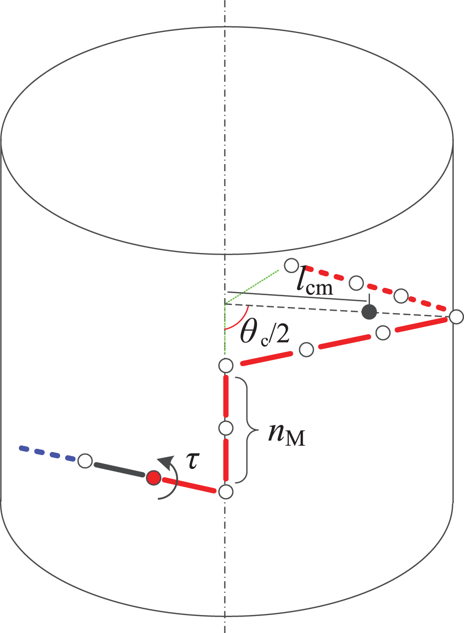
The case of where the motor bears the maximum torque when the cylinder is vertical.
The moment applied to the motor

Another case is that the cylinder is laid horizontally and the snake robot acts similar to the last case. In this case, the main factor influencing the quantity of τ consists of two parts, the moment caused by the gravity of the middle section and the head section of the snake robot. The rated torque of motor should satisfy the expression below:

The design scheme of ACL gait of snake robots
After choosing the geometry parameters of the cylinder and the friction coefficient between the cylinder and the snake robot body, the design scheme can be made based on the analyses in the fourth section. The content of design scheme includes the geometry parameters of the snake robot, the rated torque of motors, and control parameters of ACL gait.
Analyses in the fourth section give some suggestions toward the design scheme. The radius of the snake robot body should be as small as possible, which is determined by mechanical design. The parameter nH should be equal to nT. The setting of parameters of nH and nT considers if the friction force produced by the head section or the tail section of the snake robot is solely greater than the gravity of the whole snake robot. The number of links of the middle section nM determines the forward distance in each period, so it should be as large as possible. But the rated torque of motors restricts the setting of nM.
Supposing the relationship between the mass and the length of links of the snake robot is linear, that is:

The number of payload links of a single loop of the snake robot The relationship between the number of payload links and the number of links of single loop.

As shown in Figure 13, nx reaches its maximum value when l goes to
In S-type winding gait, the relationship between the number of segments of head or tail section

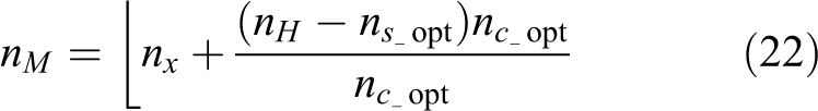
The larger the number of nM, the greater number of links within the snake robot that move forward during each period, and the more efficient the ACL gait. But the parameter nM is constrained by the rated torque of motors τmax, which derived from equations (18) and (19). Constraints are listed below:

From the above calculation, the structural parameters and control parameters of ACL gait are obtained. Two examples are given to verify the design scheme of ACL gait of snake robots. Proposing the radius of the cylinder R is 50, the rated torque of motors τmax is 20, the friction coefficient μ is 0.5, the parameters α and β in equation (17) are 0.05 and 0.1, respectively, and V-rep is applied as simulation platform.
First, the ACL gait of H-type winding is simulated. The parameters nH, nM, and nT are all set as 6, which are obtained through the nx optimal procedure. The number of single loop ns is also equal to 6 which satisfies equation (24). Figure 14 shows the climbing process of the ACL gait of H-type winding. The four phases of the gait: head opening, head folding, tail opening, and tail folding are illustrated in Figure 14(a) to (f). The whole process of ACL gait can be compared with Figure 2. Figure 14(a) shows the initial state of the snake robot winding on a cylinder, which corresponds to Figure 2(a). In the head opening phase, the snake robot extends its head section upward along the cylindrical axis, which is illustrated in Figure 14(b) and Figure 2(b) and (c), respectively. The snake robot winding cylinder with its head section in head folding phase as shown in Figure 14(c) and Figure 2(d) to (f). As presented in Figure 14(d) and Figure 2(g) to (j), the snake robot simultaneously opens the tail section and folds the other parts of body in tail opening phase. In tail folding phase, the snake robot folds the tail section and restore the body posture to its initial state, which is shown in Figure 14(e) and (f) and Figure 2(k) and (l).

The climbing process of H-type winding gait.
Second, the S-type winding gait is simulated. The parameter ns, nHs, nMs, and nTs are set as 4, 1–5, 1, and 1–5, which are also obtained through the nx optimal procedure and equation (24). Figure 15 shows the climbing process of the S-type winding gait. The four phases of the gait: head opening, head folding, tail opening, and tail folding are illustrated in Figure 15(a) to (f). The whole process of ACL gait of S-type winding can be compared with Figure 3. Figure 15(a) shows the initial state of the snake robot winding on a cylinder, which corresponds to Figure 3(a). In the head opening phase, the snake robot extends its head section upward along the cylindrical axis, which is illustrated in Figure 15(b) and Figure 3(b) to (d), respectively. The snake robot winding cylinder with its head section in head folding phase as shown in Figure 15(c) and Figure 3(e) to (g). As presented in Figure 15(d) and Figure 3(h) to (j), the snake robot simultaneously opens the tail section and folds the other parts of body in tail opening phase. In tail folding phase, the snake robot folds the tail section and restore the body posture to its initial state, which is shown in Figure 15(e) and (f) and Figure 3(k) to (m).

The climbing process of S-type winding gait.
Conclusion and future work
This article proposed ACL gait of snake robots on a cylinder. Based on parameter analyses, the gait design scheme is presented and verified by a simulation platform. The problem of a hard-to-design gait on a cylinder is solved by a method where the gait is designed on a plane and is then transformed to ACL gait on a cylinder. To prove the safety of the snake robot in motion, the kinematic and dynamic analyses of ACL gait are executed. To assure the applicability of the gait, the design scheme of ACL gait is proposed and verified by two examples of H-type and S-type winding gaits. The proposed ACL gaits only achieve the motion of a snake robot on a single pole. In the next step, the turning and avoidance motion of ACL gait will be designed to enhance the motion capability of snake robots on a complex truss structure.
Footnotes
Declaration of conflicting interests
The author(s) declare that there is no conflicts of interest regarding the publication of this article.
Funding
The author(s) disclosed receipt of the following financial support for the research, authorship and/or publication of this article: This research is financially supported by National key research and development program (2016YFC0600905), the Fundamental Research Funds for the Central Universities (grant no. 2014QNB20), the Natural Science Foundation of Jiangsu Province, China (grant no. BK20140188), the Natural Science Foundation of Jiangsu Province, China (grant no. BK20150185), and National Nature Science Foundation of China (grant no. 61603394).