
Abstract
The 12-tetrahedral robot is an addressable reconfigurable technology (ART)-based variable geometry truss mechanism with 26 extensible struts and nine nodes arranged in a tetrahedral mesh. The robot has the capability of configuring its shape to adapt to environmental requirements, which makes it suitable for space exploration. This paper considers the motion planning problem for the robot in terms of gait planning and trajectory planning. First, a gait planning method is developed that limits the forward falling angles to only 25 degrees. Then, according to the given gait, the jerk-bounded method and inverse kinematics are utilized to calculate the trajectories of the nodes and the struts, respectively. A robot system model was built in ADAMS and simulations were conducted to demonstrate the feasibility of the motion planning method.
1. Introduction
In space exploration, some terrains can be difficult or dangerous for humans to access, yet can provide valuable data for scientific research, e.g, valleys or caves on the surface of Mars. Developing autonomous systems for such complicated terrestrial environments has received considerable attention and various types of mobile robots have been designed. Wheeled robots and legged robots are two types of the most common autonomous mechanisms used for terrestrial exploration. Generally, wheeled robots can adapt to relatively smooth terrains, but is inefficient in passing over rough terrains [1]. A legged robot can walk on various types of terrain in an adaptive manner, but can easily lose stability of its gravity of centre when moving fast [2]. Crawler robots can be applied to irregular environments but are relatively cumbersome and have poor flexibility [3]. The newly proposed spherical robot has a fully symmetrical structure with the capability of omnidirectional mobility. This robot can adapt well to rough terrains, but lacks stability when passing over slops and other road conditions [4].
In addition to the complexity of terrains, space exploration generally includes diverse detection tasks; therefore, the above- noted mechanisms often cannot satisfy the requirements of exploration. In order to increase the capability of passing over complex terrains, researchers propose combining legged, wheeled, crawler and other robots into a novel mobile robot, e.g., a wheeled-crawler robot. Another approach is to design a mechanism that can reconfigure itself to adapt to different terrains such as the reconfigurable robot and metamorphic robot. A reconfigurable robot takes modular structures that can be reorganized to adapt to different task requirements and environments. Although this type of robot can adapt to some extent to a variety of tasks and environments, its structure is constrained by the size of its basic building blocks and a lack of transformation patterns. A metamorphic robot is designed based on metamorphic theory and can change it's configuration and degrees of freedom (DOFs) automatically to adapt to functional requirements [5].
The above mobile robots have the ability to pass through general obstacles but have difficulty passing through steep slops, large gullies and narrow caves. The tetrahedral rolling robot proposed by NASA is an addressable, reconfigurable technology (ART)-based variable geometry truss mechanism that consists of nodes and extensible struts arranged in a tetrahedral mesh. This type of robot can reconfigure its shape to adapt to different types of terrain environments, which makes it very suitable for irregular and complex environments encountered in space exploration.
Three generations of tetrahedral rolling robot prototypes have been proposed and designed by NASA since 2004 [6]. The first generation was a 1-tetrahedral robot consisting of four nodes and six struts, with an extension ratio of about 2:1. The robot can move its centre of gravity from its base and achieve a tumble by changing the strut lengths. The second generation was a 12-tetrahedral robot with 26 struts featuring nested square tubes, inside of which were steel cable and pulleys driven by a power electric motor with a planetary gearhead and worm gear. The third generation was also a 12-tetrahedral robot, the struts of which were made up of new material and adopted nested screws with an exoskeleton, which greatly reduced the weight of the robot. The struts can achieve a 5:1 extension ratio with the expectation of climbing a 40 degree slope.
Since the 12-tetrahedral robot is a complex system with multi-struts, multi-nodes and highly dynamic, the motion planning problem is a challenging one that has received considerable attention. In [7, 8, 9], the authors designed and analysed gaits for a 4-, 6-, and 8-tetrahedral robot based on a simulating walker model. Specifically, in [10], the authors developed a gait planning method for a 12-tetrahedral robot and proposed three types of gait planning procedures. Although the proposed method provided important references to the gait planning problem, its simplified geometrical computation can only be used by the reduced model. In [11, 12], the authors designed a prototype for the single tetrahedral robot, then proposed a motion planning strategy and presented the toppling condition for the robot based on its kinematics. In [13], the authors analysed the kinematics of the different motion phases of a 1-tetrahedral robot and presented the rolling critical condition.
In this paper, we present a detailed motion planning method for the 12-tetrahedral robot. First, a gait is planned for the robot, the forward falling angles of which are constrained to be only 25°, which greatly reduces the impact force of the ground on the robot during its falling. Then, the jerk-bounded method [14] is adopted to plan the trajectories of the robot nodes and the inverse kinematics is solved to obtain the trajectories of the corresponding driving struts. A model of the 12-tetrahedral robot was established in ADAMS and simulations were conducted to verify the feasibility of the proposed motion planning method.
The remainder of the paper is organized as follows. In section 2, we present the model and the kinematic model for the 12-tetrahedral robot. In this section, we also present the rolling condition and the external contact model. In section 3 we propose a motion planning approach, including gait planning and trajectory planning. Simulations are conducted in section 4. Finally, conclusion are presented in Section 5.
2. Model and kinematics analysis of the 12-tetrahedral robot
2.1. Model of the 12-tetrahedral robot
The 12-tetrahedral robot is an over-constrained, close-chain mechanism consisting of 26 struts, eight external nodes and one central node, as shown in Figure 1. The robot is initialized as a cube, with one strut along each edge and only one strut along one diagonal of each facet. The central node is connected to the other eight external nodes via eight struts. The central node provides space for payloads such as telemetry and communication modules, and the external nodes can provide accommodation for sensors. The external nodes are highly symmetrical and can be used as landing points. Each strut is driven by two DC motors via planetary gearheads and worm gears. The struts extend or contract to collaboratively drive the robot to fall over and roll about. This type of robot has an abundance of geometrical shapes and can achieve a variety of gaits, e.g., walking, rolling over and climbing, which improves its capacity to traverse across extreme terrain topographies such as steep and deep craters, gullies, canyons, etc.
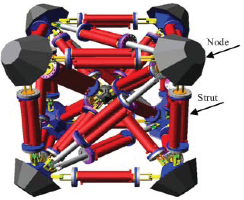
The 12-tetrahedral rolling robot
2.2. Kinematics of the 12-tetrahedral robot
The first step in the design of the robot's motion is to specify its kinematics. Thus, a systematically analytical method is needed for acquiring the node positions from the strut lengths, and vice verse. In the following, we present the direct and inverse kinematic models for the robot.
2.2.1. Inverse kinematics
Inverse kinematics is used to calculate the lengths of the struts, given the positions of the nodes. In order to analyse the kinematics, a simplified model is given(see Figure 2) for the 12-tetrahedral robot, where N0 is the central node and

A simplified model of the 12-tetrahedral robot and definition of the coordinate frames
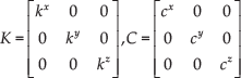
The position and orientation of Ni in frame B can be denoted by the position vector Pi and the rotation matrix

where

Let

with length

where i and
2.2.2. Direct kinematics
Direct kinematics is used to find the poses of the nodes, given the lengths of the struts. The basic unit of the 12-tetrahedral robot is shown in Figure 3 and consists of four nodes connected together with six struts, where
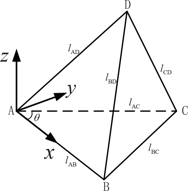
The coordinate frame fixed at a tetrahedron
Let pa, pb, pc and pd be the coordinates of A, B, C and D expressed in frame A -
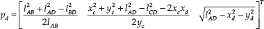
where
Given the coordinates A, B and C in the reference frame, Pa, Pb and Pc, the transformation matrix from frame A -

where

In this case, the direct kinematics of the entire robot can be achieved by sequentially choosing another adjacent tetrahedral cell and computing the unknown node positions of the latter tetrahedral using the above method.
2.3. Rolling analysis of the 12-tetrahedral robot
The 12-tetrahedral robot can achieve different motion patterns such as rolling and walking in the manner of a four-legged robot [15] by using a classic criterion of static balance (the centre of mass should project inside the convex hull of contact points) or a dynamic balance method [16, 17]. The dynamic balance method can achieve relatively high robot speed, but is sensitive to environmental variability; alternatively, the static balance method is required to keep the centre of gravity of the robot in a stable region, which renders it extremely suitable for walking at low-speeds and obstacle avoidance. More than three contact nodes are needed to keep the robot in equilibrium and the centre of gravity of the robot must be kept stable, which is achieved via the contact nodes on the ground. When stretching and/or contracting the struts to deviate its centre of gravity from the stable region, the robot will roll about, thus achieving the rolling motion of the robot.
Assume that each strut has equal mass and a multi-segment design, and that the centre of gravity of the strut is coincident with its geometrical centre. Let ms be the mass of the strut, mn the mass of the external node and mc the mass of the central node. For the sake of simplicity, the mass of each strut is split into two halves, which are added to two corresponding nodes connected by the strut, respectively. Then, the mass of N0 will change to be
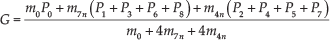
When the projection of G onto the ground deviates from the stable region formed by the contact nodes with the ground, the robot will fall over and begin rolling about.
2.4. The external contact model of the robot
When the robot falls over, certain nodes will collide with the ground and their velocities will change greatly in a short period of time, since their movements are constrained by the ground. Hence, their accelerations will be large, as will be the contact forces [18, 19]. It is assumed that the positions of the contact nodes will remain unchanged from the beginning to the end of the collision, that is, their displacements during collision can be ignored. According to the above analysis, the impact function is adopted to model the contact between the nodes with the ground. Therefore, the contact process can be considered as a linear spring-damper system. The contact model [20, 21] of

where
3. Motion and gait planning of the 12-tetrahedral robot
As a kind of autonomous mobile system, the 12-tetrahedral robot requires substantial intelligence and/or autonomy. In this paper, the 12-tetrahedral robot is considered an end-effector with underlying reflective intelligence that receives commands from the global task planning layer and moves according to the optimal gait chosen. The control system considered in this paper is given in Figure 4 and includes gait query and selection and a sensor-actuator loop. When the robot controller receives control instructions from the above layer (or a human), it first queries the gait library and selects the current gait, then transmits the instruction to the strut controllers. Finally, the strut controllers regulate the corresponding struts to extend or contract in the form of planned trajectories.

The control system of the 12-tetrahedral robot
Motion planning is an important aspect of robot control and addresses the fundamental robotics task of planning collision-free motion from a start to a goal position among a collection of obstacles. Meanwhile, the 12-tetrahedral robot is a complex system with multi-struts, multi-nodes and highly-dynamic, presenting challenges in terms of the robot's motion planning. For the sake of simplicity, in this paper, we only considered the case of selecting gait from the predetermined gait library when the controller received commands from the above layer. In this way, the motion planning problem was divided into two parts: (1) the gaits of the robot, i.e., the way in which the robot opts to move, such as tumbling or walking; (2) the motion of the struts, i.e., how to drive the struts to accomplish the chosen gait and achieve stable motion for the robot.
In [10], the authors developed a gait planning method for a 12-tetrahedral robot and proposed three types of gait planning procedures. Although the proposed method provided important references for the gait planning problem, its simplified geometrical computation can only be used in a reduced model. In this paper, we focus on a realistic model, where the obtained strut displacements can be directly input into the control system. In the following, we first present a gait planning method and then provide trajectory planning for the struts and nodes.
3.1. Gait planning for the 12-tetrahedral rolling robot
According to the properties of the 12-tetrahedral robot, there are two ways in which to plan the robot's motion: (i) directly determine the elongations of each link, similar to a 1-tetrahedral robot. However, as the number of tetrahedrons increases, the method becomes too complicated to compute; (ii) plan the positions of each node and then calculate elongation for each of the links. Clearly, the second option is more feasible than the first, since the number of nodes is significantly less than that of the links. In this paper, we only considered the case of the robot rolling about and restoring the status quo ante on a flat surface.
The gait planning method for the 12-tetrahedral robot is presented in Figure 5, where the dark circle ‘●’ denotes the nodes that contact the ground, the white circle ‘○’ denotes the nodes that are not in contact with the ground, the thick lines denote the struts, the lengths of which change during robot motion and the thin lines denote the strut lengths that remain unchanged. The motion of the robot can be divided into the following steps:
Following the above steps, the robot will realize rolling about. According to the above gait planning method, the forward falling angle of the robot is limited to be only

The rolling gaits of the 12-tetrahedral robot
3.2. Trajectory planning for the 12-tetrahedral robot
Given a gait for the robot, the trajectory planning problem focuses on generating trajectories for the nodes and struts. In this paper, the jerk-bounded method proposed in [14] is adopted to calculate the trajectories of the robot nodes. Since the 12-tetrahedral robot is a special parallel robot and proposes a unique solution to the inverse kinematics, the inverse kinematics can be solved to obtain the motion trajectories for corresponding driving struts.
In the jerk-bounded method, a concatenation of fifth-order polynomials is presented to provide a smooth trajectory between two waypoints and a sine wave template is utilized to calculate the end conditions for ramps from zero acceleration to nonzero acceleration. According to this method, the position Pi of node Ni can be formulated as a function of time,


where
Given the gait provided in subsection 3.1, the x- and z-coordinates of each node expressed in the reference frame are shown in Figure 6, where we assume that the robot rolls along the y - axis, while the x and z coordinates of nodes N1 and N4 are given by
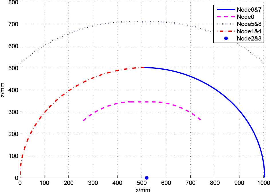
The trajectories of the nine nodes in the Cartesian frame

The trajectories of the moving struts
Although the Jacobian matrix of the robot is used to obtain the strut velocities and the Jacobian matrix and its derivative are used to achieve their accelerations, in real-world applications, the velocities


where

The trajectories of the displacement, velocity and acceleration of struts
Figure 8 shows that the change in the lengths of struts
The above method can be generalized to other trajectory planning approaches of the 12-tetrahedral robot. When a new gait is given, only the trajectories of the moving nodes need to be re-calculated and their trajectories can be utilized to achieve the trajectories for corresponding struts, based on the inverse kinematics.
4. Motion simulations of the 12-tetrahedral robot
4.1. ADAMS model setup of the robot
To illustrate the results of the above presented motion planning method for the 12-tetrahedral robot, a 3D model was built in Pro/E software and then imported into ADAMS software. In order to reduce the model's complexity and computation times yet maintain the performance of the model, certain elements were omitted that had little effect on the robot's performance, such as motor, screws, etc. Thus, the reduced model consisted primarily of nodes, struts and universal joints fixed on nodes. The physical properties and other specifications of the model are summarized in Table 1.
Primary dimensions of the 12-tetrahedral robot

Prior to conducting simulations, we needed to set parameters such as units, gravity, etc., and add constraints as follows,
A rectangular box was added below the robot to indicate that the ground was fixed to the earth through a fixed joint.
Two orthogonal revolute joints were added to each junction where the node was connected with the corresponding strut; a revolute joint was added to each junction at which the node is connected with the diagonal strut and a revolute and fixed joint were added to each junction at which the node was connected with the central strut.
A translational joint was added to each strut and translational motion, with expression
Contacts were added between the eight external nodes with the ground, where the impact function method was used to compute contact force; a Coulomb model was used to calculate the friction.
4.2. Simulation results and analysis
The trajectory data for each strut from the above motion planned method in section 3 were imported into the model. The simulation time was set to be 49.9s. The rolling process of the robot is illustrated in Figure 9.
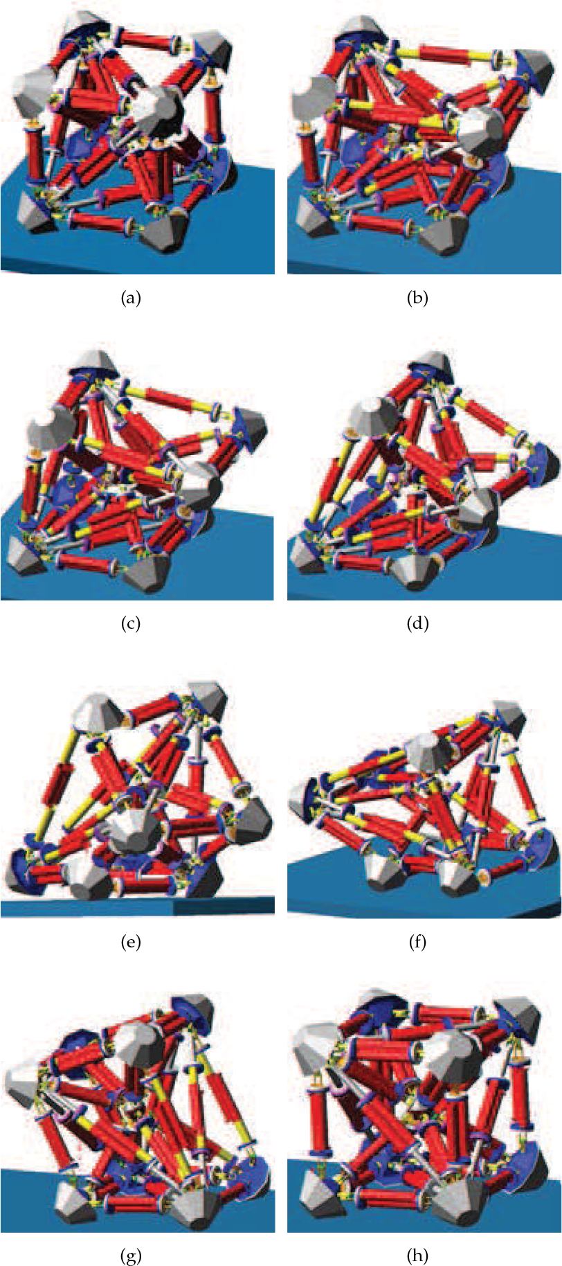
The rolling process of the 12-tetrahedral robot
It is shown that the robot followed the planned gait and completed actions from stretching to rolling to tumbling, and finally restored the status quo ante, illustrating the feasibility of the above motion planning method. It is also shown in the figures (Figure 9a–9i) that two parts of a strut stretch or shrink synchronously, which keeps the centre of mass of the strut consistent with its geometrical centre. Figure 9a–Figure 9c show the procedure during which the struts stretch, while the centre of gravity of the robot remains in its stable region. Figure 9d–Figure 9f illustrates the process from the centre of gravity deviating from its stable region, to the robot tumbling and then to nodes N6 and N7 landing. The process of the robot restoring to its initial state is illustrated in Figure 9g–Figure 9i.
The velocities of nodes N6 and N7 are illustrated in Figure 10, and the touching forces of the two nodes with the ground are illustrated in Figure 11. It is shown that the touching forces are equal to zero before the two nodes achieve contact with the ground. When the nodes collide with the ground (about
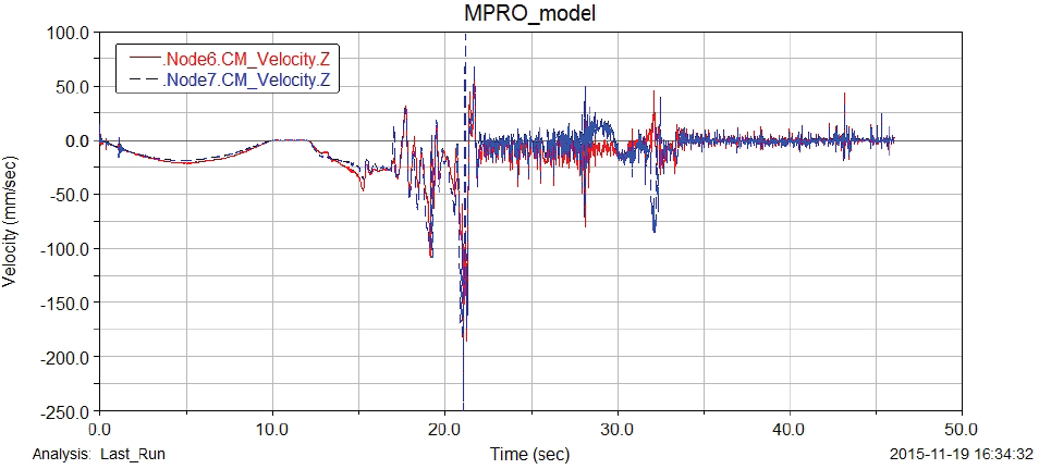
The actual velocities of nodes N6 and N7

The contact forces of nodes N6 and N7 with the ground
5. Conclusion
In this paper, we presented motion planning for the 12-tetrahedral robot, including gait planning and trajectory planning. First, we proposed and analysed a type of rolling gait based on the actual model of the robot. We then utilized an acceleration-bounded trajectory planning method to compute the expected position, velocity and acceleration for each strut. The obtained data could be directly input into the corresponding strut controller. The simulations were conducted using ADAMS to verify the feasibility of the proposed gait.
Footnotes
6. Acknowledgements
This work is supported by the National High Technology Research and Development Program (“863” Program) of China (2015AA7046411), the National Natural Science Foundation (NNSF) of China under grant no. 61403162, the NUPTSF (grant no. NY212027) and the Shanghai Academy of Space Technology (SAST201318).