
Abstract
This paper addresses the problem of making a non-holonomic wheeled mobile robot (WMR) move to a target object using computer vision and obstacle-avoidance techniques. If a priori information about the obstacles is available, pre-planning the desired path can be a good candidate method. However, in so many cases, obstacles are dynamic. Therefore, our first challenge is to make the WMR move to a desired target while autonomously avoiding any obstacle along its path. The second challenge deals with visual-tracking loss; that is, when the target is lost from the camera scope, the robot should use Dead Reckoning (DR) to get back on its path towards the target. The Visual Tracking (VT) algorithm then takes the relay to reach the final destination, compensating for any errors due to DR by calculating the distance to the target when it is within the scope of the camera. The proposed system also uses two fuzzy-logic controllers; the first controller avoids objects while the second manages the path to the target. Different complex scenarios have been implemented, showing the validity of our multi-controller model.
1. Introduction
VT is considered to be a very important tool in robotic applications, especially for navigation within unknown and dangerous environments. The use of sophisticated vision sensors allows a robot to move in such environments. Many investigations have been conducted in this context. In [1], the authors proposed an image-based visual servoing algorithm for a WMR utilizing a roof-mounted camera. The system calculates the Hessian of the image error using a second approximation method. In [2], the authors posted landmarks along the desired trajectory and taught the robot to move through them using visual servoing. A hybrid visual-servoing controller was proposed in [3]to drive a mobile robot equipped with a five-degrees-of-freedom (5-DOF) arm towards a target and to autonomously grasp and manipulate the target. The authors in [4]developed a method for controlling a two-wheeled robotic manipulator with visual servoing by using a stereo vision system to detect the size, distance and relative position of the desired target. All of these investigations used only visual servoing, which requires the presence of the object within the tracked scene during servoing. In [5, 6], a DR system was developed for the movement of a WMR. First used for the navigation of ships, this technique, when implemented in robots, depends on both the position and orientation of encoders that are fixed to the wheels; therefore, problematically, if one or two wheels of the robot spin(s), the related information is lost. In [7], an improvement of DR was developed for the movement of a WMR by using a gyroscope and a magnetic compass. Novel hardware system structure and systematic digital signal processing algorithms were introduced in [8]for the automatic localization of an autonomous mobile robot, merging DR and ultrasonic measurements. In [9], the authors presented a sensor to support a reliable odometer for mobile robot DR. The sensor was composed of two optical mice that replaced the wheel encoders; since this system is independent from the kinematics of the robot, no information was lost from wheel spin. In [10], the authors proposed a method to make a robot move and avoid obstacles in dynamic environmentsusinga combination of fuzzy logic (FL) and DR, but their method required preloaded target information.
In this paper, we present a position-based visual servoing system of a WMR, merging three algorithms. First, VT is used to find and detect the desired target. Second, FL controls the motion of the robot to reach the target and/or avoid obstacles. Third, DR estimates the position of the target when it is lost from the camera scene. In Section 2, a VT algorithm is presented. Section 3 details the WMR used here. Robot movement control using a fuzzy-logic controller is explained in Section 4, while Section 5 explains the DR estimation. The experimental results are presented in Section 6, while Section 7 presents the conclusion.
2. Visual Tracking
VT is the process of using an image and an algorithm in order to track a target. The goal is to let the robot find the desired target by using a camera. It then positions itself autonomously and moves towards that target. In this context, we propose an effective method for object-tracking. The proposed method uses colour selection to filter the acquired image, detecting all desired targets of similarly coloured pixels. Then, from amongst the detected regions or objects, shape identification finds the target, as illustrated in Figure 1.
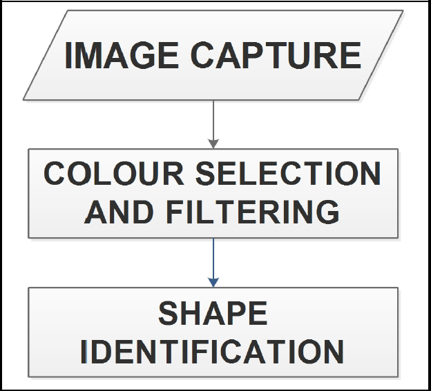
Flowchart of the VT algorithm
2.1. Colour selection and filtering
In this first stage, an RGB to HSV (Hue, Saturation and Value) transformation is applied to the captured image (from our experiments, colour selection is preferably performed on HSV maps). Then, all pixels with desired, predefined HSV values are selected. Next, noise is removed by applying a median filter. At this stage, the number of found regions is important, so any region whose area is less than one-tenth (1/10) of the target's area is removed. This ratio was obtained through experimental tests; it is related to the maximum possible distance at which target objects can be identified by the camera. Figure 2 (a-e) presents the colour selection and filtering steps.

Colour selection and filtering stages
2.2. Shape identification
After the colour selection step, the resulting image still contains different regions of the same colour as the target. Therefore, the next step is to apply the shape-identification algorithm, by comparing the shape of each detected object to the desired target template according to the following steps:
The contour of each object defined by the pixels
Once the contours are linearized, dynamic time warping(DTW)[11]is used to compare the sequences with the target template, while the best matching defines the desired target.
2.3. Calculation of the target distance and angle
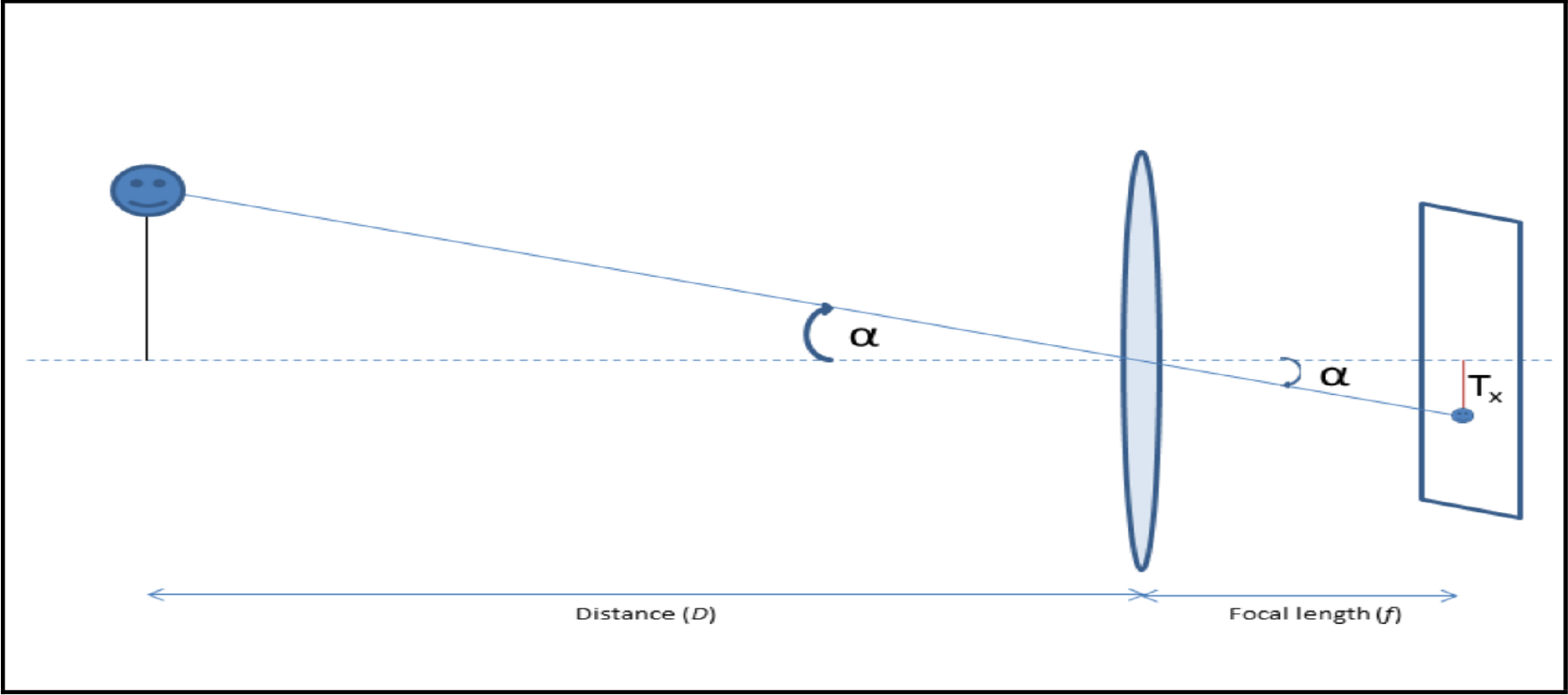
Next, we estimate the position(distance and angle) of the target in the scene (image) using computer vision techniques. For the distance, we used the relative size to determine the distance to the target, as shown in Figure 3. The relationship between the height of the target in the real plane and its height in the image plane is given by trigonometry, as per equation (1):

Relative size using an optical system

With

where

For the angle, a similar strategy is used, as shown in Figure 4. The angle to the target is given by equation (4):
Relationship between the image, the object angle and the lens focal length

where Tx is the distance between the centre of the image and the projection of the target on the image plane.
3. Wheeled Mobile Robot
A WMR has one or more independent wheels fixed on its body extremities. This kind of robot can be divided into two types: holonomic and non-holonomic. In our case, the Dr Robot version Scout-II is considered as a non-holonomic robot. This type of robot cannot instantaneously change its position in 3-DOF. Only 2-DOF are available(displacement along x-axis and rotation around z-axis), as shown in Figure 5.
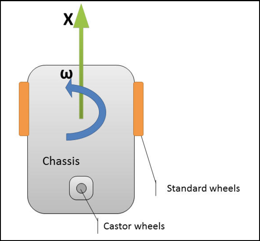
Top view of a non-holonomic robot
The kinematic model of this type of mobile robot is described by equation (5):

such that {
4. Robot Movement Using FL and Obstacle Avoidance
Fuzzy logic (FL) is a technique that allows designing controllers using a set of rules and the intuition or experience of humans to tune these rules. Contrary to binary logic, FL allows intermediate values between 0 and 1. This technique requires two important parameters to make decisions:(1) the fuzzy sets, which are a collection of related items with respective grade of truth; and (2) the fuzzy rules. Usually, the rules are developed from human experience.
If none of the sonar sensors mounted on the left (LS), front (FS) and right (RS) sides of the robot, as shown in Figure 6, detects an obstacle, the robot uses the first controller to move towards the target; otherwise, the second controller is used to avoid the obstacles, as shown in Figure7.
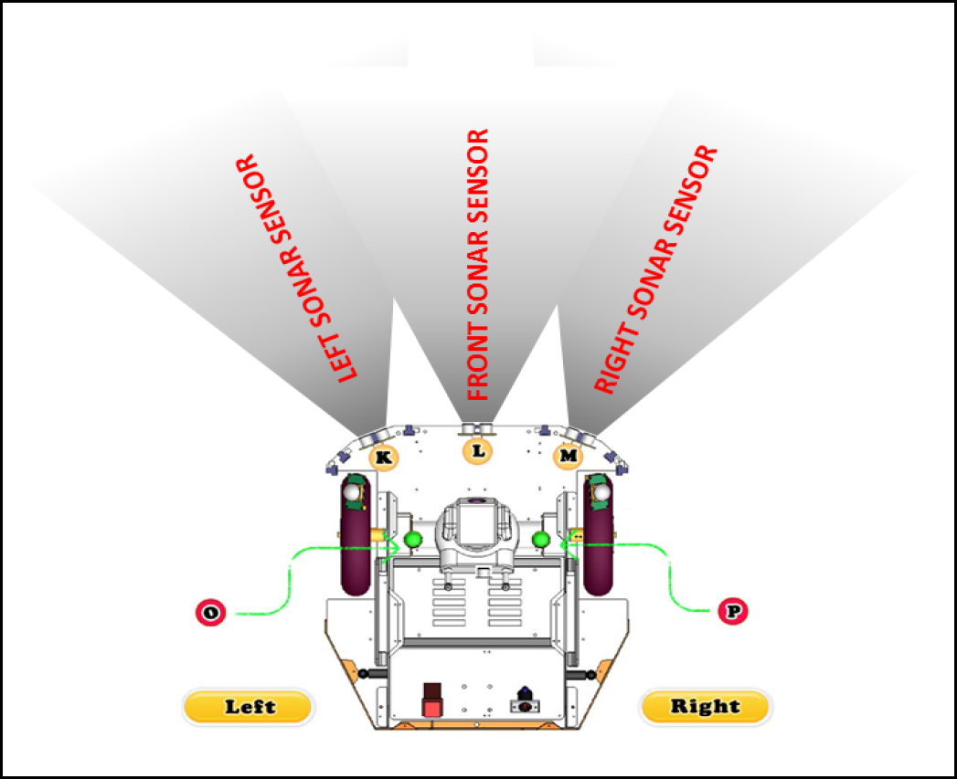
Location of the sonar sensors and the detection area (top view)

Fuzzy controllers flowchart
The next two sections describe the two fuzzy controllers in detail.
4.1. Go-to-target Fuzzy Logic Controller (GTFLC)
This controller allows the WMR to move smoothly towards the target, based on two inputs:
The distance D to the target and the angle α between the robot X-axis and the target.
Both D and α are computed and updated continuously from the VT and DR.
Then two outputs are continuously computed:
The velocities
where:

with:

and:

such that
The shape of the Membership Functions (MF)of both inputs is shown in Figure 8.
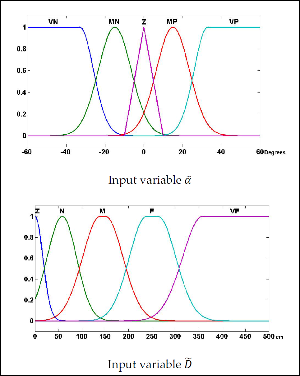
MFs of the angle and distance inputs
The fuzzy angle
The fuzzy input distance
For each wheel (right and left), we defined five Gaussian MFs as outputs, defined by
The shape of the output MFs is illustrated in Figure 9. The degree of overlap was purposely enlarged in order to make the movement of the robot as smooth as possible.
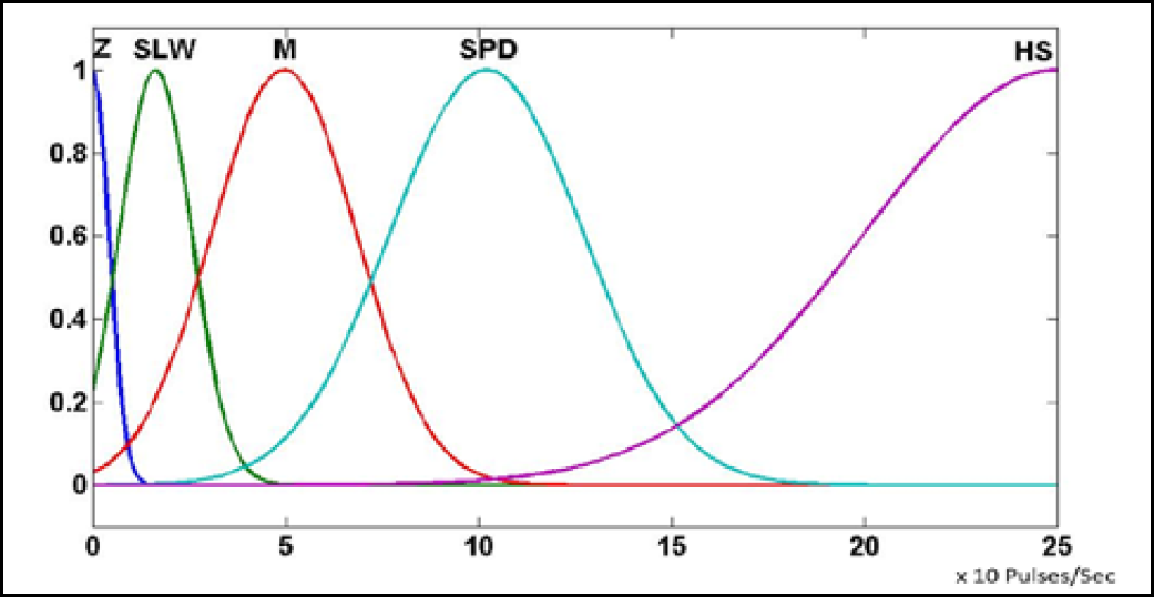
MFs of the output variables (
The fuzzy rules of the GTFLC are presented in Table 1. These rules were tuned based on different experiments and aimed to smooth the robot's path.
Fuzzy rules of the right and left wheel velocities

4.2. Obstacle Avoidance Fuzzy Logic Controller (OAFLC)
The second FL controller was designed to let the robot automatically avoid any obstacle along its path. The OAFLC considers, as its inputs, three sonar sensors as presented previously in Figure 6. Given the different input-sensor values, the OAFLC uses the fuzzy rules in Table 2 to determine the path that the robot should follow in order to avoid any collisions with detected obstacles. The outputs of this controller are the right and left wheel velocities.
Fuzzy rules of the obstacle avoidance controller

The range of each sensor has been divided into three MFs, defined as Near (N), Medium (M) and Far (F), and the output velocities take the set of values

MFs of the input/output variables of the OAFLC
5. Dead Reckoning
DR is a well-known and widely used method to estimate the position and orientation of a robot during its motion. DR uses the position and orientation at time t i-1 to calculate the position and orientation at time t i using the kinematic model of the robot defined by equation (5).
Including all the parameters of our robot (W r : Wheel radius; W d : distance between wheels; T r : number of pulses per rotation), equation (5) may be rewritten as:
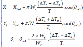
where
6. Experimental Results
The goal of this work is to develop a control system for a WMR that is able to track and reach a given target using FL, DR and VT. A flowchart of the working system is illustrated in Figure 11.

System flowchart
It starts with the initialization of the robot and its top-fixed camera. The robot tries to detect the predefined target within the actual scene; otherwise, it makes a 70° rotation in any direction (since 70° is the horizontal angle of view of the camera). If the target is still not found, the robot keeps rotating until it finds it. Once the target is found, the system enters a loop that begins by reading the values of the sonar sensors, after which the robot starts to move towards the target using the GTFLC controller. If any obstacle is detected, the system switches to use the OAFLC controller. It also synchronously activates the DR system if the object is no longer in the field of view of the camera. The tracking process finishes when the target is reached.
The control process was developed and tested using MATLAB, running on an Intel 7-2670QM, 12Gb RAM and 64-bit Windows 7 OS, with a DR Robot Scout II platform equipped with a wireless-communication interface over WiFi. The top-fixed IP camera, a D-Link 5222L, has a resolution of 800 × 448 pixels, a pixel size of 2. 8µm × 2. 8 µm, a frame rate of 25 fps, a focal length of 3. 6 mm and angles of view of (H=70, V=53, D=92).
In order to establish the improvements of the proposed system, a set of two independent scenarios was realized:
6.1. Experiment with no obstacles
The first scenario was done in a no-obstacles environment, using the same robot and controller in [10]. The robot is intentionally put at (X=3. 0m, Y=2. 0m) from the target. The comparison concerned the travelled path, the error at final position and the elapsed time to reach the target. Our system shows a smoother and shorter path, as illustrated in Figure 12, leading to an average shorter time to reach the target as shown in Table 3.

Scenario 1: Wheeled robot movement without obstacles
No-obstacle comparative results over five experiments

Notice that our proposed system gets the WMR closer to the target, without prior knowledge of the position of the target as in [10]. In our case, it is detected automatically using VT, an advantage of our system. In this type of environment, the controlled motion of the robot ensures the target is never lost from the scene.
In this type of environment (no-obstacle) only, the GTFLC controller is used to control the motion of the robot, as it minimizes the angle
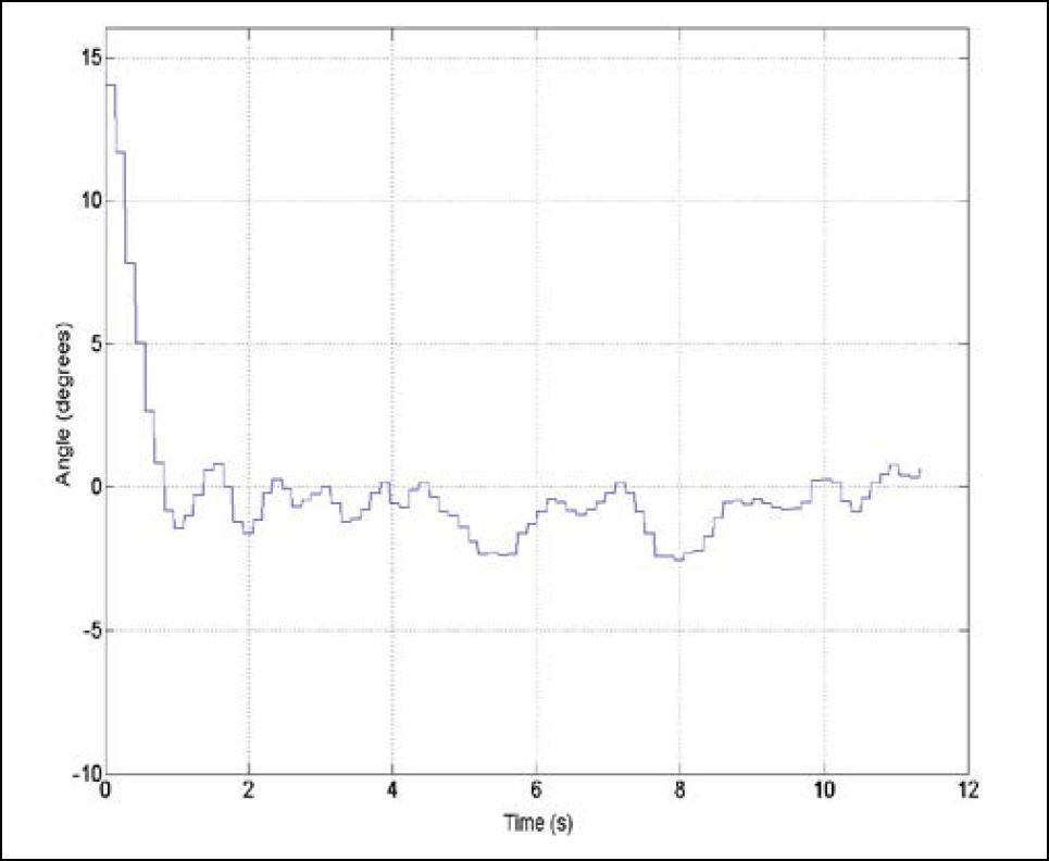
Angle error between the robot and the target
6.2. Experiment with obstacles (all components enabled)
In the second scenario, different obstacles were put between the robot and the target (the target can still be seen by the camera over the obstacles).
Although the robot directs towards the target, obstacles are avoided smoothly, as illustrated in Figure 14. If the target was lost from the camera scene, the robot would use DR to update the angle/distance to the target (circle marks). When the target is redetected, the robot switches back to VT (cross marks). The green symbols (cross and circle) denote the robot using GTFLC, while the red symbols denote the robot using OAFLC.

Scenario 2: Navigation with obstacles
7. Conclusion
In this paper, we propose a system for the control of the displacement of a WMR, which combines VT and DR to determine the position of the target and the robot instantaneously. In addition, two fuzzy controllers are implemented: the first controller for obstacle avoidance and the second controller for robot displacement.
The proposed system presented good performance and robustness through diverse implemented scenarios, while a comparison with a previous fuzzy controller has also shown that VT not only helps to direct the robot into smooth paths towards the target, but also compensates for any DR errors.
The system can be improved by using visual odometry instead of DR, and the camera will be used for detecting and avoiding obstacles.
Footnotes
8. Acknowledgements
This work was supported by the Research Center and the Center of Smart Robotics Research, College of Computer and Information Sciences, King Saud University.