
Abstract
This paper presents a novel three-degree-of-freedom (3-DOF) parallel manipulator and introduces its mechanical structure. Analytical solutions of the forward kinematics have been worked out, and all configurations of this robot are graphically displayed. On the basis of several special positions in the kinematics, a task workspace is prescribed to find the smallest feasible dimensional parameters of the robot. An algorithm describing this method is also introduced. This method can easily find appropriate parameters that can size a robot having the smallest workspace enclosing a predefined task workspace. This improves the design efficiency and ensures that the robot has a small mechanical size possessing a large workspace volume and, in terms of dimension design, meets the lightweight-design requirements. With examples illustrating the design results, we further introduce a design stability in dextoensure that the robot remains a safe distance from the boundary of its actual workspace. One prototype of the robot has already been developed.
1. Introduction
Various types of mechanism have been applied in many robotic fields. Indeed, certain parallel mechanisms have recently attracted considerable attention. Parallel mechanisms have many advantages over serial mechanisms, such as high stiffness, large payload capacity, compact structure, low inertia and high accuracy. These characteristics allow parallel robots to be used in various fields, such as space docking prototypes, flight training devices, vibration and earthquake simulators, mining products, tunnel shields, forging manipulators and assisted surgeries [1]. As a significant example of such a mechanism, Gough [2] invented a tyre-testing device having a 6-DOF. Later, Stewart designed the Stewart platform for flight simulation and analysed the kinematics of this platform [3]. Hunt termed a class of mechanisms, including the Stewart platform, as parallel manipulators [4]. Takeda et al. [5] present a 6-DOF parallel robot, the main advantage being that the output link's position and orientation are decoupled, as well as the spherical parallel mechanisms [6,7]. Since then, a large number of parallel manipulators have been built and several distinctive designs and analytical approaches have been introduced [8,9].
The design approaches to parallel manipulators fall into two main categories: type synthesis and dimensional synthesis [10]. Type synthesis attempts to find all possible configurations generating a specified motion pattern of the moving platform [11–13]. Once the configuration has been built, the geometrical design parameters of the mechanical structure should be determined; this is called dimensional synthesis. Dimensional synthesis is an important stage of optimal robot design because the performance of a given robot is very sensitive to its geometry [14–16]. Amongst all kinematic measures, the workspace is one of the most important criteria in optimally designing a parallel robot. Thus, workspace analysis has continued to attract substantial attention over the years. There is a rich body of literature addressing the design problem of developing good performance in a manipulator based upon workspace optimization. In turn, many approaches have been proposed.
Liu et al. found a relationship between the desired workspace and design parameters, proposing an optimal design method to determine the geometric parameters of a 3-DOF parallel manipulator [1]. Meanwhile, Huang [17] presented a general method to determine a compatible orientation workspace for various 6-DOF parallel manipulators. In considering a reachable workspace, Gao et al. [18] presented a new method to determine the configuration architecture parameters of a novel 5-DOF parallel machine. The method makes it possible to describe the relationship between the reachable workspace and the configuration dimensional parameters of the parallel machine. Yang et al. [19] proposed a composite workspace that requires a specified working capability of a Stewart platform, and presented two analytic methodologies to determine whether the workspace of a mechanism satisfies design requirements. Pond and Carretero [20] proposed a Jacobian approach that determines the optimal architecture in terms of the condition number of the Jacobian matrix. Bonev and Ryu [21]proposed the orientation workspace: the set of all attainable orientations of an end-effector about a fixed point. Chablat et al. [22] introduced an interval analysis algorithm to determine the largest regular dexterous workspace of a 3-DOF parallel robot, for which the velocity amplification factors remain within a predefined range throughout the workspace.
Another important problem is designing a parallel manipulator for a given workspace. This problem has been investigated by Boudreau and Gosselin [12], who presented a genetic algorithm approach to determine the architectural parameters of a Stewart-Gough platform that has a workspace as close as possible to a prescribed workspace. Madrid [23] expressed the design problem of telescopic manipulator arms by using an analytical formulation for the workspace boundary. Kosinska et al. [24]presented a method to describe the given workspace and check whether a manipulator with certain parameters fits the design requirements of a Delta-4 manipulator. This method is easy to understand and implement, but it relies on heavy computation. Parenti-Castelli et al. [25] proposed an efficient optimal dimensional synthesis method for the DELTA robot. The 3-UPU parallel mechanism for a given workspace was studied by Badescu and Mavroidis [26]. Similarly, in [27], the genetic algorithms used for optimization of a 3-DOF planar manipulator, with respect to the prescribed workspace, determined the architecture of a manipulator together with its position and orientation.
A good design is one in which a manipulator of small mechanical size possesses a large workspace volume [28]. The workspace volume of a manipulator is one of its important factors. The goal of optimal manipulator design is to achieve the largest volume of the workspace. To meet this requirement, the parameters of the parallel robot must be optimized when the desired task workspace is assigned. Although many design approaches have been proposed for this problem, much effort in relation to it continues.
In this paper, we attempt to explore a new method of parameter design for parallel manipulators for a given workspace. We design a novel 3-DOF parallel robot with three limbs (TLPR). This paper presents an idea to distinguish other de-coupled manipulators [5,29] that employs only passive revolute joints to achieve translational motion of the moving platform. This will significantly simplify kinematic analysis and ease of application. The forward-position kinematic solutions are shown to be reducible to a first-degree polynomial equation, which will reduce the complexity and computation time for control. The proposed new parameter design method is based on several key points that we have found in this study. Considering the weight restriction, the robot has small size and light weight.
This paper is organized as follows: the characteristics of the robot and geometric parameters, including the mechanism, are introduced in Section 2. The modelling of the kinematic equations and workspace is addressed in Section 3. Analysis of the singularity and link interference is carried out in Section 4. The small-size design method is introduced in Section 5. The results are presented via a set of examples in Sections 6. Finally, the conclusions are presented in Section 7.
2. Configuration of the proposed robot
2.1. Characteristics of the TLPR
The TLPR robot has a parallel kinematic structure with three identical kinematic chains connecting the fixed platform to the moving platform. Each kinematic chain is configured by two passive revolute (R) joints, an active prismatic (P) joint and a universal (U) joint. Thisdesignhas3-DOF; namely, three translations along x, y and z directions. The three active joints are driven by three servomotors and the displacements are measured by linear potentiometers. The robot is supplied by an AC power source, with the use of three AC-DC transformers. There are three main advantages of this structure:(1)the kinematics are determined only by three lengths of prismatic actuators, so that it is easier for the computer to position the robot in inverse and forward kinematics; (2) the simple kinematics can meet fast control requirement and reduce the solution time for software, which helps the system to improve its real-time control capability; and, (3) reconfiguration can be easily realized due to the modularized design approach and sufficient workspace.
2.2. Geometric parameters of the TLPR
With reference to the mechanical structure design, each limb has been assembled on the base platform at a certain angle. The axes of R joints and the guide directions of the three P joints intersect at a virtual common point p.
The ith, i=1, 2, 3, limb connects to the base platform through a universal joint, while q
i
, i=1, 2, 3, denotes the point where the two axes of the U joint intersect at the base platform. The points q1, q2 and q3 lie evenly on a circle of radius  , while the U joints are tangent to the circle.
In this study, the geometric design parameters of the ith limb are defined by the vectord1= [α1α2β2Lηi1ηi2] T . As shown in Fig. 1c,α1 denotes the angle between the axis of the P i joint and the axis of Ri1 joint,α2 denotes the angle between the axis of the Ri1 joint and the axis of the Ri2 joint,β2 is defined from the geometric centre of the line from the moving platform to the axis of the Ri2 joint, and L is the radius of the base platform, i=1, 2, 3. Angles ηi1, i=1, 2, 3 are defined as the angles between the projection of the axes of the actuated P joints on the base platform, with a given reference in that plane in the state of the initial configuration, as shown in Fig. 1b. Angles ηi2, i=1, 2, 3, are defined between the projection of the axis of the Ri2 joint of the ith limb on the moving platform, with a given reference in that plane, as shown in Fig. 1a. Moreover, β1 is defined as the angle between the axis of the actuated P joint and its projection on the base platform in the state of the initial configuration; the input parameters, l i , i=1, 2, 3, respectively denote the actuator length with respect to the initial values.

Geometric parameters of the TLPR
2.3. Mobility analysis
All the joints in the proposed mechanism are associated with unit screws, which form a screw system. The common constraint is defined as a wrench reciprocal to each twist of the screw system. The number of the common constraints is denoted by λ, which can be expressed as
The general Grübler criterion [10] is given by:

where M represents the mobility of the mechanism, d denotes the order of the mechanism, d=6-λ, n is the number of links, g is the number of kinematic joints, and f i is the freedom of the ith joint.
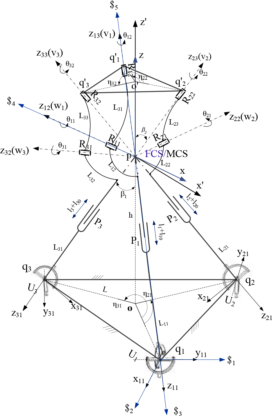
The motion of the end-effector is completely determined by the combined constraints of all limbs. The constraint wrench can be expressed by a screw system reciprocal to the limb twists. For example, one limb constraint screw system is shown in Fig. 2, in which the limb twist in an arbitrary configuration is expressed as:
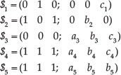
The limb constraint wrench is
Kinematic diagram of the TLPR
3. Kinematics and workspace of the TLPR
3.1. Inverse and forward kinematics of the TLPR
The kinematic diagram of the TLPR is illustrated in Fig. 2. For convenient analysis, a fixed coordinate system (FCS) is fixed to the base platform; its origin is always fixed at the initial position of the point p. Its z axis is defined as the axis in the direction from o to p, while its x-axis is parallel to the vector
As previously mentioned, each link has been set up on the base platform at a certain angle, and the fixed points

where

As the base platform is an equilateral triangle, the position vectors

where li0 = the initial length of the limb, and l i = the input length of the ith parametric joint.
Eqs. (3) are the foundation equations for the solution of kinematics problem in this paper. For a given position of the end-effector, one solution for lengths of the prismatic joints, li, i=1, 2, 3, is obtained. The solution of the inverse kinematics issue is, therefore, complete.
The forward kinematics solution is shown at the intersection of the point p created by the length of the prismatic actuators li. According to Eq. (3), by substitution of the points


Choosing any two of the above three equations, we can eliminate the variable z, as well as obtain two equations with variables x and y. Subtracting Eq. (4) from Eq. (5), and Eq. (4) from Eq. (6), the following two equations are obtained, which eliminate the variable z in variables x and y:


To solve these equations we need to eliminate variable y from Eqs. (7) and (8) simultaneously; the resulting equation will contain only variable x. This equation is:

Given that the three identical limbs are uniformly configured on the base platform, the angles


where L0=L cosβ1 in the above equations.
Eqs. (10–13) are the polynomial solution for the forward kinematics problem of this robot with at most two real solutions; the Cartesian position of the moving platform is denoted as

The two solutions of the FPKs for two configurations of the TLPR
3.2. Jacobian matrices of the TLPR
The Jacobian matrix is defined as the matrix map between the velocity of the end effector and the vector of linear actuated joint rates [30]. Using Jacobian matrices, singularity analysis and various kinds of singularities for the TLPR robot will be investigated.
The kinematic constraint equations, Eq. (3), are defined in the base frame FCS. Therefore, for ith limb of the TLPR robot, both sides of the Eq. (3) can be time differentiated to yield:

where

where

where
3.3. Workspace of the TLPR
The workspace of any manipulator is generated by scanning all of the joints through their ranges of motion in order [24]. In this project, the workspace of the TLPR robot is defined as a region of the three-dimensional space generated by the three prismatic joints in the FCS frame. We wish, therefore, to determine the feasible regions for prescribing workspace for the design problem.
As previously mentioned, the configuration is determined, and the forward kinematic Eqs. (10), (11) and (12) will be used to determine the workspace volume for the TLPR robot by scanning the values of the interval-actuated joints from their minimum to maximum values, when the different circles L and anglesβ1 are considered.
Henceforth, the parameters L and β1 are to be used in the optimal design of the manipulator according to the relationship of L and β1; when β1 equals π/4,the manipulator has good isotropy in its initial configuration. Thus, the workspace volume is determined by the geometric parameter L when the actuated joints parameters l i are available. Assuming the radius of the base platform L=590 (mm),the extreme positions of the three-dimensional Cartesian space generated by a stroke interval from l min to l max fulfils the forward kinematic, as illustrated in Fig. 4.

Extreme positions of the three-dimensional Cartesian space generated by stroke intervals from −L/3 to L/3
4. Singularity and link interference analysis
4.1. Singularity analysis
In singular configuration, the mobile platform may instantaneously gain one or more unconstrained degrees of freedom and the performances of the robot degenerate and the structure may be damaged [31], while singularity limits the workspace of a robot. Therefore, a usable robot workspace may be obtained by avoiding such singulars from the theoretical workspace. The employed method consists the analysis of the two Jacobian matrices to determine these singular configurations.
4.1.1. Inverse kinematic singularity
It is known that a PM is in an inverse singularity when the inverse Jacobian matrix is equal to zero. As shown in Eq. (15), since the matrix

Thus, the inverse singularity does not occur for the TLPR robot.
4.1.2. Direct kinematic singularity
Direct singularity for the TLPR occurs when


where
Note that s
d
=0,
Examples of the direct singularity configurations are sketched in Fig. 5.

The two direct singularity configurations of the TLPR
Direct kinematic singularities for the TLPR can be avoided by choosing values for joint variables l
i
, i = 1, 2, 3 that result in a non-singular matrix
4.2. Link interference analysis
For avoiding collision, this is an essential operation before the determination of the interference among mechanical parts. The interference, which might occur in TLPR, can be simplified to the five situations.
As shown in Fig. (2), the interference can be measured by the angles θi1 and θi2, where i=1, 2, 3. For ith limb, the vectors from

while its unit vectors are given by:

The vectors
where
Finally, the vectors
while its unit vectors are given as:

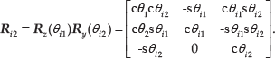
Therefore, the rotation matrices associated with each limb from the frame Li1CF to the frame FCS, which are denoted as

Referring to the Fig.2, the rotation matrices from frame Li1CF to frame Li2CF are written as:

where
Now it is easy to write the rotation matrices from the frame MCS to the frame Li2CF as:

By combining Eqs. (26) and (27), we can obtain


Corresponding to the mechanical structure design of the links, link geometry of a specified is defined. In Fig. 6(a), interference between the links Li3 with the Li2 in one limb is checked by studying the relative rotation of link Li3 with respect to the link Li2, i=1, 2, 3. In the view of the specified link geometry, the minimum angle θi1 rotation around zi2 axis is π/10, and the maximum angle is π. In this situation, the interference can be avoided by limiting theθi1 as: π/10<θi1<π. The second situation occurs when the link Li3 interferes with the moving platform, in which the minimum angle θi2 rotation around zi3 axis to moving platform is π/6, and the maximum angle is π. Thus, π/6<θi2<π represents the joint as free to move without mechanical interference inside the workspace.

(a) Angle-interference; (b) distance-interference
As shown in Fig. 6(b), the third situation occurs when the link Li2 interferes with each other in adjacent limbs; meanwhile, in Fig. 7, when the cross-shape of the Li2 is a squared area and the length of a side is d, we can ensure that there is no interference if the minimum distance between two links following condition is: D
zi
>
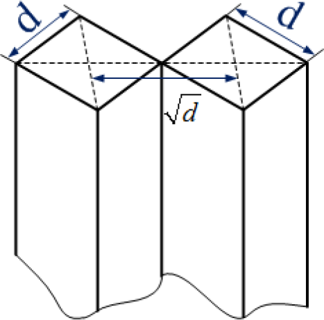
The distance-interference problem, and the minimum safety distance between two links in the condition of non-interference
From the above analysis, there are two kinds of interference in the system: one is angle-interference in one limb, and the other is distance-interference in adjacent limbs. The angle interference for TLPR can be avoided by calculating values for joint variables θi1 and θi2 using Eqs. (29) and (30), which result in non-interference angles. Modifying the shape of links can partly reduce interference.
The position analysis of the TLPR robot in the workspace, where the moving platform is constrained to translate with respect to the base, can be determined by singularity and interferences, thereby locating the singular configurations that make s d =0 and u i =0 of Eq. (19). The interference can be avoided by calculating values for joint variables θi1 and θi2 using Eqs. (29) and (30), which results in non-interference angles and modifying the shape of links.
5. Dimensional Synthesis of the TLPR Robot for the Prescribed Workspace
To exemplify the new design method, we limited the boundary of the workspace to a given shape. The objective of the dimensional design is to determine the geometric design parameters for the TLPR, and ensure it has a small mechanical size, possesses a large workspace volume and fits the lightweight design requirements.
5.1. Small-size design algorithms
In most cases of manipulator design, the manipulators have a large volume of workspace. However, in practice, the calculated volume is not useful in the task workspace. To improve the design efficiency, we propose a design method based on minimizing a design algorithm using the forward and inverse kinematics.
The small-size design algorithm for the TLRM robot with a desired workspace consists of the following steps:
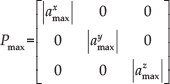
An expected volume in space W is given; all points are to be reachable by the centre of the moving platform. Depending on the shape of the prescribed workspace W, the vectors of three maximum projection points of W on the x, y and z axes in the frame FCS can be written as:
The initial design parameters for the prescribed workspace through three projection points can be formulated in closed form by forward polynomial design with Eqs. (10–12), respectively. The solution of the initial design parameters is denoted I*, where I=*(q1, q2, …q
n
) is an unknown vector of parameters, and
Finding the key points when a three-dimensional prescribed volume of workspace is given means that all of the boundary points are determined. That is, there exists a point on the envelope of the given workspace that requires the maximum driving stroke or maximum joint angle. These points are called the key points
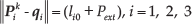
By solving the minimization of design parameters using the inverse kinematics, the extreme values of the actuated joints can be calculated at each key position. In this method, we introduced the extreme values of actuated joints as a function for the design parameters of the mechanical structure. Hence, if the actuated joint is prismatic, we will have
5.2. Examples for given workspaces
In the following, to demonstrate the new design method, we limited the shape of the given workspace to a cube and a composite (a cube and a cylinder).
5.2.1. Example 1
In this example, the dimensions of the TLPR robot are to be determined to find the smallest size of workspace capable of containing a volume W, given that the shape of the volume W is a cube; the length of a side is a, as shown in Fig. 5, and all points from the centre of the moving platform of the given workspace meet the following equation:

The extreme projection points of the position vectors of W along the x, y and z directions can be expressed as:

These points lay in the platform's boundary edge, which caused the extreme interval stroke length of the actuators, while the specified values of the prismatic actuators were selected based on the TLPR robot.
We use Eqs. (10–12) in the condition of the position vectors

By solving Eqs. (34) and comparing three extreme results for

In view of the shape of the prescribed workspace and the structure of the TLPR robot, we find that when the moving platform is at positions
In this case, we expect to find a surface closest to the points
By solving the above equations, the minimization of the design parameter L can be obtained.
5.2.2. Example 2
In this second example, we will consider the case in which the given workspace is a composite volume composed of a cube and a cylinder, as shown in Fig. 9. All points in the given workspace meet the following equation:

Through comparison and analysis of this composite volume, the extreme projection points along the x and y axes can be written as:

By re-using Eqs. (10–12), the following equations can be constructed:

By solving Eq. (39) and comparing three extreme results for


The scheme of the cube workspace
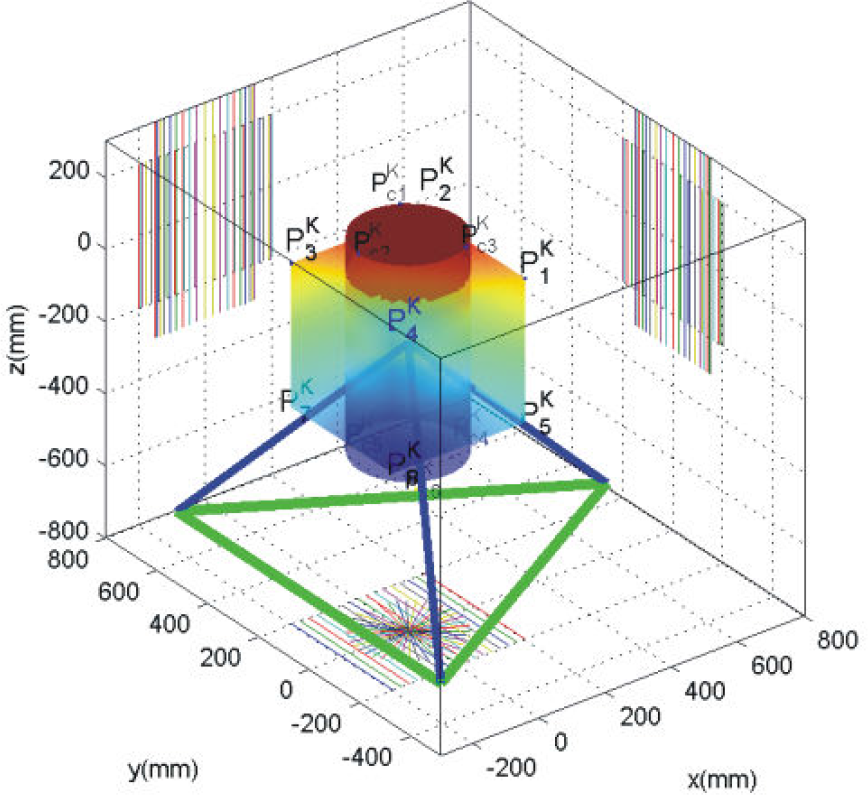
The scheme of the composite workspace
The boundary points were considered in the work cube and cylinder. Fig. 10(a) shows a horizontal view of the workspace with the design parameter L derived from the given workspace of a cube; we note that the upper vertices of the cube completely surpass the boundary of the workspace. In Fig. 10(b), we note that the upper vertices of the cube are located exactly on the boundary of the workspace under the design parameter L derived from the given workspace of the cylinder. Additionally, the magnitudes of key points are measured in the FMS frame, and

Horizontal view of two slices of the workspace in the composite volume
Using a similar method, we can obtain the minimum of the values of design the parameter L for the manipulator with a workspace that includes the given volume in space W.
5.3. Stability of design index
Let us suppose that

For the specified volume of the task workspace, if the manipulator's workspace includes the desired workspace with predefined margins in the x, y and z directions, the design workspace is stable, such that W > 0; if the desired workspace surpasses manipulator's workspace, this means W < 0. The design stability index for a manipulator with the largest volume of the workspace is defined as:

where
6. Results
In the following, a variety of results illustrates the capabilities of the proposed methodology. The prototype of the TLPR robot is used for generating a suitable workspace and obtaining the above examples.
Dimensional design results for the prescribed workspace of the TLPR robot are given in Table 1. The optimization ends when all joints are free to move without mechanical singularity and interference inside the prescribed workspace.
The kinematics design variables

Fig. 11(a) shows the TLPR robot having a workspace, which includes the prescribed workspace with the smallest parameter L, when the prescribed maximum usable inscribed workspace of the TLPR is a cube, with edge a, that is symmetrical about the initial position.

Cartesian workspace and prescribed workspace for the TLPR robot with the smallest mechanical size
Fig. 11(b) shows the volume of the reachable workspace of the TLPR robot; the maximal useable inscribed workspace is a cylinder with radius R, height 2H, and symmetrical about the initial position. The workspace of the TLPR encloses the cylinder with the smallest parameters.
Fig. 11(c) shows the given workspace as a compound workspace containing a cube with edge a, a cylinder with a radius R/2, and height of 2R; the TLPR is capable of matching this case with suitable parameters.
As shown in Fig. 12, with the above example of cubic workspace design parameters, a prototype of the 3-DOF parallel robot has been developed.

The performance and 3-D prototype of the TLPR
7. Conclusions
This paper has presented a novel 3-DOF parallel robot and introduced its mechanical structure.
Analytical solutions of the forward kinematics have been worked out by using an analytical method; according to these solutions, two configurations of this robot are graphically displayed. Based on one configuration, the Jacobian matrices were derived for two types of conventional singularities. Additionally, the angle-interference and distance-interference are presented.
The proposed parameter design approach uses several key points based on the analytical solutions of the forward and inverse kinematics of this robot, which can easily find appropriate parameters that can allow for a robot with a smallest workspace to include a predefined task workspace. This method can improve the design efficiency and ensure that the robot, with a small mechanical size, possesses a large workspace volume; in terms of dimension designing, it meets the lightweight design requirements.
We introduced a design stability index that can ensure that the robot has a safety margin, when scanning all positions of all the pre-specified shape in the workspace. Noting that the TLPM-II robot reaches the key points, it must be driven towards some stable configurations.
A prototype of a3-DOF parallel robot has been developed using the proposed method. This method can clearly be extended to other types of parallel mechanisms.
Footnotes
8. Acknowledgements
This project is partially supported by the National Basic Research Program of China (973 Program, Grant No. 2013CB035500). The authors would like to thank the Editor, Associate Editor, and anonymous reviewers for their constructive comments.