
Abstract
The need to recharge the batteries of a mobile robot has presented an important challenge for a long time. In this paper, a vision-based wireless charging method for robot energy trophallaxis between two robots is presented. Even though wireless power transmission allows more positional error between receiver-transmitter coils than with a contact-type charging system, both coils have to be aligned as accurately as possible for efficient power transfer. To align the coils, a transmitter robot recognizes the coarse pose of a receiver robot via a camera image and the ambiguity of the estimated pose is removed with a Bayesian estimator. The precise pose of the receiver coil is calculated using a marker image attached to a receiver robot. Experiments with several types of receiver robots have been conducted to verify the proposed method.
1. Introduction
Mobile robots have found application in homes and in various industries. In recent years their use has been extended to other areas of application — on battlefields, in space and in disaster-hit areas. Some mobile robots have a combustion engine and fuel tank on them, but most are operated electrically and powered by an on-board battery. If a robot moves and works for a long time, the battery becomes exhausted and then recharging is needed. The problem of battery recharging for mobile robots has long been an issue. For a home robot, especially a vacuum-cleaning robot, automatic recharging is generally implemented and various types of recharging systems have been proposed. Because home mobile robots do not have enough position accuracy to make unassisted contact with a recharge station, a guide mechanism around the recharge station is used to correct the position of the robot for stable contact between it and the recharge station [1]. A robot finds the recharge station using vision [2] or an infrared LED and then a guide mechanism assists the robot with making contact with the recharge station. However, if a guide mechanism cannot be used, such as when there is a need to recharge robots of various sizes or robots on uneven terrain, then a contact-type automatic recharging system is infeasible. An electric contact may also become contaminated due to dust and humidity. For these situations, wireless power transmission (WPT) can be considered. LG Electronics patented an idea for an automatic robot recharging system based on WPT [3], but this patent does not present the details of how to align the transmitter-receiver coils of robot and recharging station. Even though WPT allows more positional error between the coils than contact-type charging systems, the rotational and translational position error between the two coils sharply reduces the energy transmission efficiency, as shown in the Appendix. A vision-based coil alignment method for a wireless robot auto recharging system was presented in [4]. WPT also has its weaknesses, such as a low power transmission rate and efficiency. That will be improved upon in the future, but for now robot auto-recharging with WPT has those restrictions. Another applicable area of WPT in robotics is trophallaxis. Trophallaxis of mobile robots means that recharged robots exchange energy resources in turn with robots in their own proximity, for robot autonomy [5, 6]. Schioler and Faisul proposed a battery exchange method between robots that has a special mechanism for exchange [5]. A battery exchange technique shortens the recharging time, but it requires an expensive and complicated mechanism and is hardly viable for use between different types of robots that have different-sized batteries. On the other hand, WPT is applicable when the robots only have matched transmitter-receiver coils. Robots can also transfer or receive energy bilaterally with the very same coils, with some additional circuits [7]. The basic idea of trophallaxis with WPT was proposed in [8], but [8] presented only coil recognition. In this paper, a vision-based WPT charging system for trophallaxis is proposed and developed. Compared with an automatic recharging problem where a charge station is fixed and usually confined to one shape, for robot trophallaxis the transmitter robot has to recognize a receiver robot among the many types of robots and estimate the pose of the receiver robot in order to align the coils. After the location of the receiver coil is found, the transmitter-receiver coils have to be aligned accurately for high transfer efficiency. In prior research [8], the transmitter robot succeeded in energy delivery only when the transmitter robot was in front of the receiver coil. Furthermore, the entire process for trophallaxis was not presented. The main contributions of this paper are that the transmitter robot delivers energy to a receiver robot without prior knowledge of the pose of the receiver robot and that a complete procedure of vision and WPT-based robotic trophallaxis is proposed.
The organization of this paper is as follows: in section 2 the background of this research is surveyed. In section 3 a camera-based trophallaxis system with WPT is proposed. Section 4 describes an experiment and finally section 5 presents our conclusions.
2. Background of research
2.1 Wireless power transmission (WTP) [9, 10]
Wireless power transmission, or wireless power transfer, means that a power source supplies energy to a system by means of a time-varying electromagnetic field, without interconnecting wires. WTP techniques are classified as non-radiative and radiative. With a non-radiative technique, power is transferred over short distances using various coupling methods such as inductive coupling, resonant inductive coupling, capacitive coupling and magneto-dynamic coupling. With inductive coupling, which is widely used for commercial purposes, power is transferred between two coils by a magnetic field. The transmitter and receiver coils form a transformer and an alternating current in the transmitter coil induces an electromotive force (EMF) in the receiver coil. Then the induced EMF generates AC currents that are rectified to a DC current that drives a load directly or charges a battery. Currently, inductive coupling is used to drive or charge small home appliances, computers, cellphones and cars.
With a radiative technique, power is transferred over substantial distances in the form of electromagnetic radiation. Laser beams and microwaves are forms of electromagnetic radiation that are suitable for power transfer.
2.2 Pose estimation
Pose estimation is the estimation of the angular orientation and position of a 3D object from a 2D image. The 3D pose is estimated from approximate 3D model points and 2D image points. Some researchers have used a 3D CAD model [11, 12]. Pose can also be estimated by comparing an input image with a data bank of images of an object at different poses. Athitsos proposes a 3D hand pose estimation method in which the closest matches for an input hand image are retrieved from a data bank of synthetic hand images [13] and Thomas proposes a multi-viewpoint object class detector based on an image data bank [14]. Schemes for estimating the pose of humans, vehicles and buildings are popular topics of pose estimation. Andriluka presented a method for the pose estimation of a crowd with a single 2D camera [15].
Research articles on pose estimation of mobile robots are few in number. Researchers usually assume that the pose of a robot is calculated by the robot itself and that the robot can teach its pose to another robot via communication, for problem simplification. However, in practice, robots that do not have precise position sensors and exterior supervisory control systems cannot estimate their pose with respect to world coordinates because positional error accrues as time goes on.
2.3 Feature-based object recognition
A feature point is an informative point of an image. There are several types of feature points: edges, corners and blobs. Feature detection is finding a feature point on an image. Commonly used feature detectors are Harris, FAST, ORB, MSER, BRISK, FREAK, SIFT and SURF. After feature detection, features are extracted and feature descriptors are built [16–20]. During the past decades, the established feature detectors were SIFT and SURF. SIFT (Scale-invariant feature transform) applies the difference of Gaussians function to smoothed and resampled images and then defines the maxima and minima of the result as feature points. SIFT is invariant to uniform scaling and orientation. SURF (Speeded Up Robust Features) is a local feature point detector and descriptor that uses the determinant of the Hessian to detect the blob. SURF can be used to recognize objects and faces. BRISK and ORB are new feature detectors of low computational cost, which may be alternatives to SURF and SIFT.
To recognize an object, descriptors of the query image and the trained images are compared and matched descriptors of the two images are found. Common matchers are the Brute force matcher and FLANN (Fast Library for Approximate Nearest Neighbours) [21].
3. Energy Transfer between two robots
3.1 Flows of energy transfer
A transmitter robot is one that has enough charged energy and so transfers extra energy to another robot. The transmitter robot is equipped with a camera, a distance sensor and a transmitter coil. A receiver robot receives energy from a transmitter robot. At the beginning of the energy transfer, a transmitter robot approaches a receiver robot. Then, when in the vicinity of the receiver robot, the transmitter robot captures the image of the receiver robot and classifies the type and pose of the receiver robot by comparing it with images in a data bank. If the degree of belief of the estimated pose (defined in section 3.2) is greater than a threshold, the transmitter robot is in effect convinced of the estimated pose and then approaches the coil of the receiver robot. We assume that the position of the coil of each receiver robot is attached in a fixed position with respect to the receiver robot's coordinates. If the degree of belief is less than a threshold, the transmitter robot starts moving around the receiver robot to get more images from a new viewpoint. The pose is estimated recursively using a Bayesian estimator, until the degree of belief becomes greater than a threshold. After the transmitter robot moves to the side where the receiver coil is provided, the transmitter robot calculates the precise position of the receiver coil with a new image and moves into a docking position. A docking position is defined to be the closest point from the receiver robot at which the transmitter robot can get the pose of the receiver coil and the two robots can align coils with minimum motion. If the transmitter robot cannot find the receiver coil on the side where it should be, after exploring a full turn around the receiver robot, the energy transfer ends in failure. A flow chart of energy transfer between robots is shown in Figure 1.

Flows of energy transfer
3.2 Classification of robot type and pose estimation
3.2.1 Construction of the image data bank
To find the coil of the receiver robot, the transmitter robot needs to know the pose of the receiver robot. In this paper, an image-databank-based robot pose estimation method is used. The image data bank method is suitable when 3D models of the receiver robots are not available. However, the estimated pose is then not as accurate and the method yields only coarse values.
Suppose that the total number of types of receiver robots is NR. In advance, an image data bank is built with images obtained at evenly divided viewpoints, NV points, surrounding each type of robot, as shown in Figure 2. Angle values are assigned to each of the viewpoints and 0 degree is assigned to a pitch axis direction that extends off of the right side of the robot. Then viewpoint space is defined.

Robot Viewpoints
x: Robot viewpoint index state, ɛ [1, N = NR x NV]
z: Observation
The feature points of each image are extracted and the description vectors are saved in the data bank.
3.2.2 Pose estimation based on an image data bank
A captured image of the receiver robot is matched with each image of the data bank, as shown in Figure 3, and the pose can be estimated using the best matched image. However, commercial mobile robots usually have a bilaterally symmetrical appearance and are monotonously coloured, so there is the possibility of ambiguity. If the degree of belief of the estimated pose is less than a preset threshold value, the transmitter robot moves to the next viewpoint and a grid-based filter, which is a finite-state version of recursive Bayesian estimation, and accumulates the observations recursively until the degree of belief becomes greater than the threshold value. The equation of the filter is as follows [22]:
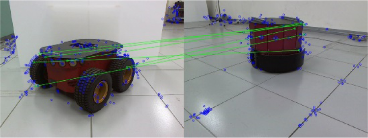
Feature point matching (Left: trained image, Right: captured image)
Prediction:
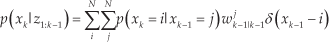

Update:


Here, subscript k refers to the kth iteration, superscripts i or j of w indicate the ith and jth elements of w, δ(•) is the Kronecker delta, wk|k-1 is the prior weight and wk|k is the posterior weight. w0|0 is a similarity score between the captured image and each image in the data bank. In this paper, the degree of belief is the ratio of the maximum element of posterior weight wk|k to the second largest element of wk|k.
3.3 Coil alignment
As shown in the Appendix, excessive positional and angular error between transmitter-receiver coils reduces the transfer efficiency. The estimated pose of section 3.2 does not have sufficient accuracy for efficient energy transmission, so once again the pose of the receiver robot has to be calculated based on an image. Figure 4 shows the coordination systems of robot and camera.
Where,
CA: Camera coordinate at the docking position
CB: Camera coordinate at the current position
RA: Robot coordinate at the docking position
RB: Robot coordinate at the current position
K: Camera calibration matrix
sHq: Homogeneous transform from coordinate s to q

Coordinate systems of robot and camera. (a) Coordinate system at the docking position and current position. (b) Coordinate system of a robot. (c) Camera coordinate at the docking position and current position.
Before the transmitter and receiver robots align the coils, the transmitter robot has to move from the current position to a docking position by making use of a camera image. The image of the receiver robot at the docking position is trained in advance. Then the homogeneous transform from RB to RA is obtained using Eq. (5). Orientation and position of the coordinate RA, the position of the docking point, are represented with R and tp in Eq. (5), with respect to the current position, RB.

In Eq. (5), RBHCB and CAHRA are known. From the two images captured at the docking position and current position, feature points are extracted. The homogeneous transform matrix CBHCA is obtained from point correspondences of the two images. Let P1, P2, … and PM be 3D points that are represented by coordinate CA and let p1, p2,.. and pM be pixel values of the corresponding points with respect to CB in Figure 4 (c). Then,
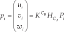
With at least four correspondent points, that is M ≥ 4, CBHCA can be obtained [23].
4. Experiment
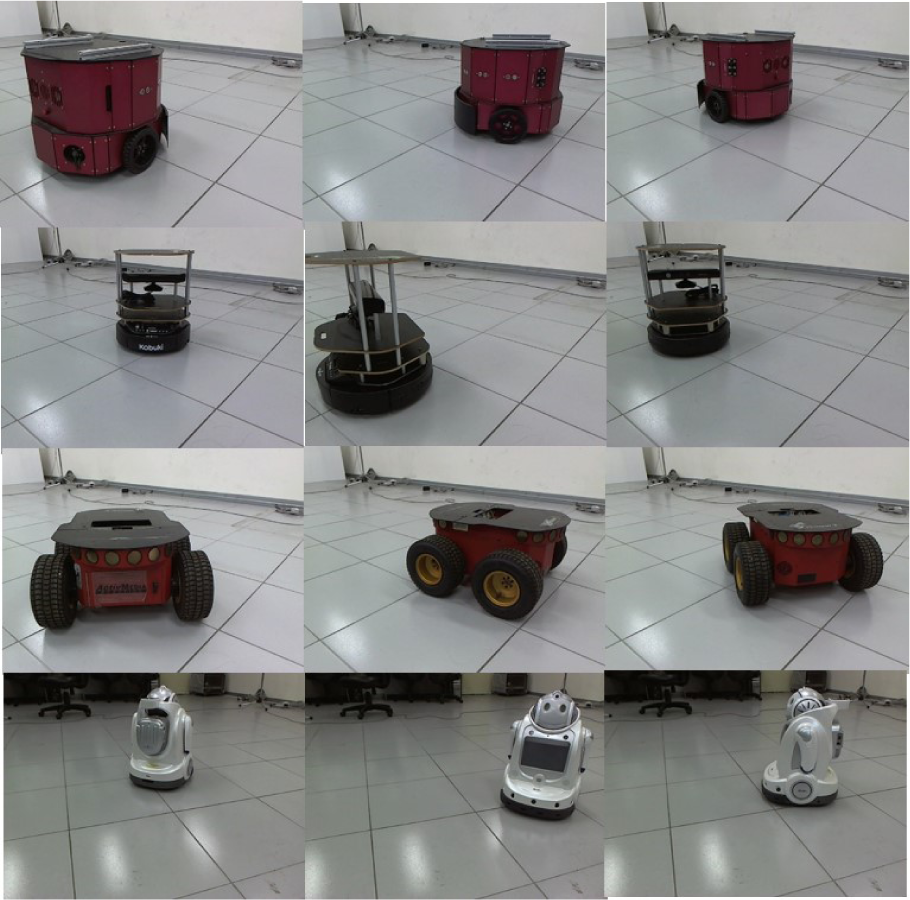
In the experiments, four types of target robots are used: R1, R2, R3 and R4, and the image data bank is as shown in Figure 5. Images were taken at every 45° and the total number of images is 32.

Robot Image data bank (R1, R2 and R3 from the upper robot)
Feature points and descriptors were extracted using the SURF detector and extractor. The transmitter robot captured images of the receiver robots at different viewpoints and the captured robot images are as shown in Figure 6 and are labelled from I0 to I11. Descriptors of the captured image and the trained images in the data bank are matched using the FLANN based matcher and the decision results are shown in Table 1. The threshold value for the SURF Detector was 400. After the matched keypoints were found, the outliers were eliminated with RANSAC and the reprojection threshold was 5.0.
Pose recognition result

Captured images at different viewpoints, I0 (Upper Left) ∼ I11 (Lower Right)
Images I7 and I8 are falsely recognized and have low degrees of belief; I1, I4 and I9 are rightly recognized but the degrees of belief are low. The matching scores between the trained images and the captured images are shown in Figure 7.

Matching scores
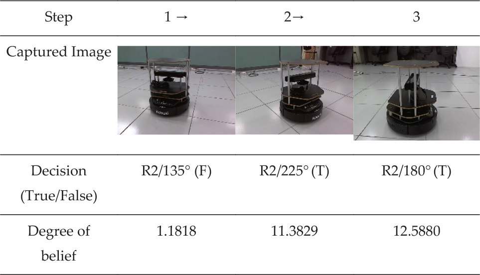
If the degree of belief is lower than a threshold, 1.8 in this experiment, the transmitter robot moves to the next viewpoint. The threshold value was empirically determined. Each type of robot can have different threshold values. In Table 2, step 1, the first estimation result from the robot image is robot R2 and 135°, which is an incorrect result, and the degree of belief is 1.1818. Therefore, in step 2 the transmitter robot moves to the next viewpoint and takes another image. After iteration of the recursive Bayesian filter in steps 2 and 3, the estimated pose is R2/225° and R2/180°, which are true poses at these viewpoints.
Recursive Bayesian estimation result

After the transmitter robot finds the pose of the receiver robot, the transmitter robot calculates the rough position of the receiver coil. While facing the side where the receiver coil is installed, the transmitter robot takes the image of the receiver robot to find the precise position and orientation of the receiver coil. In [8], the receiver coil image was used with canny edge detection and the Hough transform to find the accurate pose of the receiver coil, but in this experiment a chessboard marker attached on the receiver robot is used, because it ensures robustness and repeatability, and many established algorithms are available for finding feature points on the chessboard marker. Figure 8 shows the marker image at the docking position, at test Point A and at Point B. The inner corners of the chessboard marker were extracted as feature points and from the images and Eq. 5, the Point A and Point B coordinates were respectively (x:-254.9mm, y:-128.3 mm, θ: −26.5°) and (x:262.3mm, y: −160.7mm, θ: 36.6°) apart from the docking position.

Marking image at docking position (left), Point A (middle), Point B (right)
A flow chart of coil alignment between the robots is shown in Figure 9. Figure 10 shows how the transmitter robot of our experiment, with only go-straight and rotate motion like a vacuum-cleaning robot, moved to the docking position. The dashed line in Figure 10 shows the sequence of the motion, not the real trajectory. Figure 10 shows that the transmitter robot could find the docking position with the captured image and dead-reckoning.

Flowchart for docking procedure
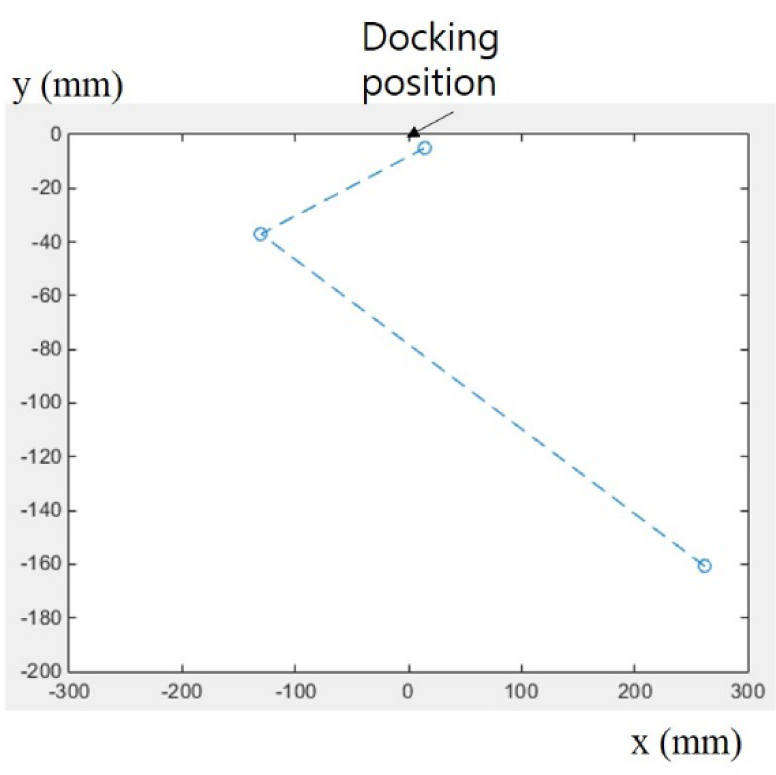
Coil alignment with dead-reckoning and motion like a cleaning robot
Figure 11 shows a coil installed on the transmitter robot. It has parking magnets and springs in order to compensate for a small amount of positional and rotational error.

Coil module
5. Conclusion
Recharging a mobile robot is an important problem. In this paper, wireless charging between two robots for energy trophallaxis was presented. A robot pose estimation method based on an image data bank and feature recognition was proposed to achieve efficiency in the energy transfer. The transmitter robot that had extra energy estimated the pose of the receiver robot and approached the side where the receiver coil was installed based on camera image. To estimate the pose, an image data bank containing multiple viewpoint images of the receiver robot was constructed and with SURF detector and FLANN matcher the pose of the receiver robot was recognized. To reduce the ambiguity of the estimated pose, a grid-based filter was used. This pose estimation method was not accurate and only gave information about the side of the receiver robot on which the receiver coil was installed. To align the transmitter-receiver coil accurately, a marker that indicated the pose of the coil was attached on the receiver robot and an accurate pose of the coil was calculated using the marker image. In our experiment, the transmitter robot moved to the docking position using only the motions of a vacuum-cleaning robot and the marker image.
With WPT trophallaxis, a robot can reduce the time needed to return to the charge station for recharging. This will increase the energy efficiency of a multi-robot system. Compared with trophallaxis with a battery exchange method, the proposed method eliminates the need for a complex mechanism. Currently, the efficiency and transmission rate of WPT is not satisfactory, so there is a limitation regarding the need to fully charge a bulk robot battery. However, when the efficiency of the WPT is improved, the proposed method will be an effective solution for robot energy autonomy.
Footnotes
6. Acknowledgements
This research was supported by the Basic Science Research Program through the National Research Foundation of Korea (NRF), funded by the Ministry of Education, Science and Technology (2012R1A1A2040141).
Appendix
Figure A1 shows charging current with respect to lateral and angular misalignment. An induction coupling type commercial module bq25046 was used. With this module, the transmitter robot has position accuracy of 1cm and angular accuracy of 20°, for efficiency.