
Abstract
The rapidly increasing number of electric ships in use worldwide necessitates the development of fast, secure, and autonomous shore-based charging systems that can meet the unique conditions of shipping, including the limited time of ships at dock owing to set travel schedules and the highly dynamic operating conditions of marine environments. However, existing marine charging systems remain insufficiently reliable and efficient. The present work addresses this issue by proposing an innovative vision-controlled automatic robotic charging system composed of a robotic charging station and an auxiliary alignment platform. First, the visual data captured by a single camera on the charging station is applied in conjunction with the You Only Look Once YOLO11 object detection model to identify circular targets on the alignment platform with a rough degree of accuracy. Then, the precise target coordinates are obtained from detailed edge features extracted from the rough target image using Canny-Zernike and least-squares algorithms, and the target coordinates are finally located within the camera coordinate system based on the target pose calculated by the Infinitesimal Plane-Based Pose Estimation algorithm. Finally, the charging process is commenced after transmitting the precise target coordinates to the robotic arm of the charging station and the plug and socket are connected. The effectiveness and accuracy of the proposed charging system are demonstrated based on the results of full-scale real-world experiments with a prototype automated charging system, where the system provides a displacement error within 0.8 mm from the precise target position, with an angular positioning error within 0.7°, which is sufficient for meeting the accuracy requirements of charging system connections in practical engineering applications.
Keywords
Introduction
A dramatic increase in the sales of electric vehicles is well known to have occurred in recent years owing to the numerous benefits of these vehicles, such as avoiding the unsustainable use of fossil fuels, reducing CO2 emissions, and lowering energy costs. Similarly, the total number of electric ships in use worldwide has also increased rapidly for the same reasons. 1 However, electric ships face significant challenges not confronted by electric vehicles, such as technical issues associated with marine environments, the development of shore-based ship charging infrastructure, and improved ship power systems and operations. One of the more significant constraints associated with the development of ship charging infrastructure is that the docking time of ships is limited because shipping routes follow a set timetable. Hence, charging operations must be conducted in the most efficient manner possible to utilize their limited docking time fully. Moreover, highly efficient charging operations are even more crucial because of the limited energy storage capacity of electric ships requires that they dock more often than ships run on conventional fossil fuels. Furthermore, the global scope of shipping operations and the need for human safety makes the development of manned charging stations both prohibitively expensive and undesirable. 2 Hence, widely distributed ship charging infrastructure that can provide fast, secure, and autonomous charging without human intervention is urgently required to support a rapidly expanding fleet of electric ships.
Existing automated shore-based charging systems have been developed as robotic systems that initiate power transfer to ships by making physical electrical connections to the standard power sockets with which electric ships are equipped for recharging their batteries via vision-based target detection conducted using deep learning methods. 3 Here, vision-based methods based on monocular vision technology are particularly cost-effective because motion control can be conducted based exclusively on images captured by a single camera, and no extra hardware is required. Hence, monocular vision technology has been applied to develop automatic charging systems for electric vehicles and electric ships. For example, Quan, Lou 4 utilized shape-based matching approaches and the Perspective-n-Point (PnP) algorithm for automatically identifying the charging ports on electric vehicles based on pose information. Yu, Wang 5 proposed an automatic target alignment approach based on monocular vision for guiding underwater charging platforms. Nonetheless, the development of efficient automated charging operations is subject to additional challenges due to the influence of dynamic operating conditions, such as waves, air currents, wind, partially free-floating movements, and loading and unloading processes. 6 This issue was addressed by Güney, Bayılmış 7 by applying the You Only Look Once YOLOv5 object detection model to identify the position of the charging socket on an electric ship roughly in an initial step, and then applying the highly accurate control obtained by laser sensors to make the final connection between the robotic charging station and the on-board charging socket with good reliability. However, the use of laser sensors greatly increases the cost of the automated charging system. As a result, existing automated marine charging systems remain insufficiently reliable, efficient, and inexpensive to support a rapidly expanding fleet of electric ships. The characteristics of the above methods are summarized in Table 1.
A comparison of some automatic charging systems.

The present work addresses this issue by developing the automated robotic shore-to-ship charging system illustrated in Figure 1. Here, greater efficiency and reliability are achieved by designing the charging system with two main components, including a robotic charging station with the plug guided by vision data obtained from a monocular camera and an auxiliary alignment platform with circular targets separate from the charging socket onboard the electric ship. Here, the use of circular targets is advantageous for vision-based control systems owing to the rich gradient information along the circumference of the target and precise positioning facilitated by the center point. In this research, the YOLO11 object detection model is utilized to identify the circular targets on the auxiliary alignment platform in real time with a rough degree of accuracy in a coarse positioning stage because its enhanced backbone network and neck architecture offers strong feature extraction capabilities, and attains high precision and recall while preserving computational efficiency. The YOLO11 model is trained using a custom dataset assembled from a comprehensive set of target images captured at different times of the day, in varying positions, and under a full range of weather conditions. In addition, a subset of the dataset is applied as the testing dataset for assessing model performance. Then, the auxiliary alignment platform accurately aligns the plug and socket through an alignment device in a fine positioning stage that relies on detailed features extracted from the rough target image to obtain the precise center coordinates of the target, while the center coordinates of the target are located within the camera coordinate system based on the target pose calculated by the Infinitesimal Plane-Based Pose Estimation (IPPE) algorithm. Hence, the proposed shore-to-ship charging system shortens connection times and improves energy transfer efficiency without increasing the cost due to the need for costly sensors. Moreover, the proposed system can support a rapidly expanding fleet of electric ships, and thereby contributes toward reduced CO2 emissions from maritime transportation by promoting the use of electric vessels.

Proposed automated robotic shore-to-ship charging system.
The remainder of this report is organized as follows. Section “Related work” provides a thorough review of object detection algorithms and monocular vision technologies. Section “Methods” comprehensively describes the proposed shore-to-ship robotic charging system. Finally, the results of full-scale real-world experiments are presented and analyzed in Section “Experimental results”, and Section “Conclusion” summarizes the article and discusses future work.
Related work
Object detection tasks have received significant attention in recent years. For example, object detection methods based on deep neural networks (DNN) have addressed the visibility and occlusion problems of conventional image processing algorithms, such as Oxford-MKL, deformable part models (DPMs), NLPR-HOGLBP, and selective search. 8 Moreover, DNN-based approaches have dominated the object-detection landscape by providing quicker and more accurate object detection results than can be obtained by conventional means. Of particular importance for automated object detection tasks, deep learning models can extract the key features of images autonomously without human intervention. Generally, object detection approaches can be classified as two-stage and single-stage detectors. Two-stage detectors generate candidate regions within an image in the first stage, and then classify and localize the generated regions in the second stage. Examples of two-stage detectors include region-based convolutional neural networks (R-CNNs), fast R-CNNs, faster R-CNNs, and feature pyramid networks (FPNs). 9 In contrast, single-stage detectors eliminate the separate region proposal phase of two-stage detectors by identifying objects in a single pass. Accordingly, the speed and simplified design of single-state detectors make them ideal for real-time applications. Notable examples of single-stage detectors include single shot detectors (SSDs) and YOLO variants. 10 Of particular interest, YOLO11 is a single-stage object detection algorithm launched by Ultralytics in late 2024. 11 Specifically, YOLO11 is an enhanced version of the YOLO series that displays exceptional accuracy, rapid speed, and outstanding performance in real-time object detection owing to its incorporation of transformer-based modules and updated feature extraction techniques. 12 However, target detection alone is often unable to determine the position of a target with sufficient accuracy without further extracting the features in target images via pose estimation approaches.
Existing vision-based target pose estimation approaches can be divided into monocular vision and stereo vision. 13 Here, stereo vision can use projection geometry and feature point matching to estimate target position, but its operational range is constrained due to the limited common field of view of the two image channels. 14 In contrast, monocular vision methods employ only a single image to obtain pose information, and therefore require no image-matching process. 15 Hence, monocular vision methods are inexpensive, versatile, and have a simple structure compared with stereo vision methods. For example, a monocular vision method was proposed to estimate the three-dimensional (3D) pose of a target from some standard geometric features, such as circle and rectangle shape features. In contrast, the IPPE algorithm mainly resolves correspondences between the pixel coordinates of images and world coordinates, and has been applied to estimate target posture. 16
Methods
The operational flow of the proposed monocular vision-based robotic charging system is illustrated in Figure 2. As can be seen, the robotic charging system continues to capture images of a ship approaching the port until a circular target is detected, and the approximate location of the circular target is then calculated in the coarse positioning stage. The control system then interacts with the robotic arm to move the plug until it arrives at the alignment device on the auxiliary alignment platform, which limits the displacement of the plug to an appropriate range within a single dimension, and the connection between the plug and socket is established in the fine positioning stage. The coarse-to-fine localization method uses YOLO11 to identify the circular target in the image, followed by edge detection for fine localization of the target's center point. This two-stage approach leverages the strengths of both techniques: YOLO11 quickly narrows down the target area, providing a reliable initial position. Edge detection performs precise, sub-pixel level center point calculations within the defined region. This strategy balances speed and accuracy and reduces computational load and improves robustness against background interference. This combined approach achieves higher precision than using either method alone. The three main steps associated with plug and socket connection process are illustrated schematically in Figure 3. The energy transfer process begins immediately once the connection is established, and continues until the charging process is completed. Meanwhile, the auxiliary alignment platform ensures a tight connection between the socket and plug under environmental disturbances. After the charging process concludes, the robotic arm returns the plug to its original position in expectation of the next charging operation.

Operational flow of the proposed charging system.

Schematics illustrating the plug and socket connection process: (a) robotic arm grips the plug; (b) robotic arm places the plug on the alignment device of the auxiliary alignment platform; (c) completion of the plug and socket connection.
Primary components of the designed charging system
The primary components of the robotic charging station, auxiliary alignment platform, and interconnecting hardware are presented in Figure 4. The details of each main component are listed in the Appendix. Here, the air gripper is employed on the robotic arm to grip the plug, and the robotic arm is moved to a preset position using a motion control card. The calculated target pose information is automatically transmitted to the robotic arm via direct Ethernet communication. The robotic arm then places the plug on the auxiliary alignment platform according to the calculated target pose information, and the information that the robotic arm has reached the target position is transmitted wirelessly to the control system on the auxiliary alignment platform. The control system then sends signals to the servo drives, which move the plug toward the connection position according to programmed motor speeds and positions using a motion control card. Finally, the linear motor module moves the plug within the limits of a displacement sensor to the specified target position received wirelessly.

Primary components of the designed charging system.
The overall automated charging process can be deduced more intuitively from the images of the prototype charging system and auxiliary alignment platform presented in Figure 5. As shown in Figure 5(a), the robotic arm grips the plug, and the visual information from the camera is applied in Figure 5(b) to detect the circular targets on the auxiliary alignment platform when the ship is stationary. Next, the robotic arm places the plug on the auxiliary alignment platform based on the determined target positions, as illustrated in Figure 5(c). The robotic arm then releases the plug and returns to its rest position. The linear motor modules then move the plug forward within the limit of the displacement-limiting device, as depicted in Figure 5(d). Finally, the plug is firmly connected to the socket for power transmission, as shown in Figure 5(e).

Practical automated robotic charging system implementation: (a) robotic arm grips the plug; (b) circular targets are detected via monocular vision; (c) robotic arm places the plug on the auxiliary platform; (d) line motor modules move the plug toward the socket; (e) plug is firmly inserted into the socket.
As such, the proposed system minimizes the requirement for manual assistance during charging, although human operators are required to supervise system operations and execute controls under emergency conditions. In addition, regular and preventive maintenance is required to guarantee the reliability of long-term operation. 17 However, the specific maintenance periods for an autonomous charging system can be expected to vary depending on the specific operational conditions of a given port location, system components, and regulatory requirements.
Coarse positioning stage
YOLO11 network architecture
The YOLO11 network architecture is divided into three basic modules, including backbone, neck, and head modules. The backbone utilizes a Cross Stage Partial DenseNet (CSP-DenseNet) structure, the neck includes a Transformer-based Feature Pyramid Network (T-FPN) structure, and the head incorporates lightweight dynamic prediction modules operating under an anchor-free mechanism for final target identification. The architectural flow of the YOLO11 network is illustrated in Figure 6 with a 640 × 640 pixel image with three color channels as input and roughly delineated targets within square boxes as output.
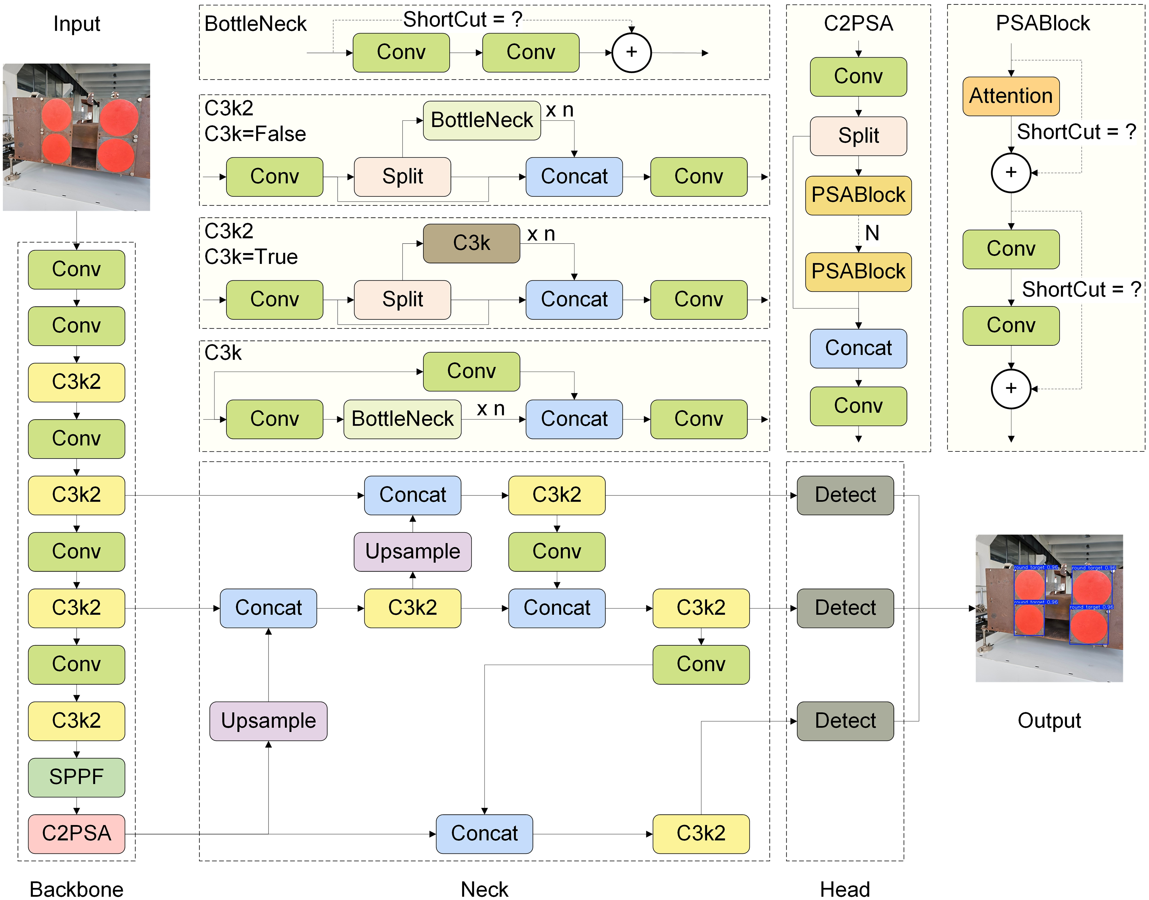
YOLO11 network architecture with a 640 × 640 pixel image with three color channels as input and delineated targets as output.
We further point out that the YOLO11 network architecture includes various design enhancements improving its localization and classification performance. For example, YOLO11 replaces the C2f module in the backbone of YOLOv8 with a C3k2 module that offers enhanced adaptability in multiple application scenarios. In addition, the C2PSA module, which is a convolutional block with two parallel spatial attention blocks (PSABlocks), as shown in the inset of Figure 6, was applied after the SPPF module to enhance the attention mechanism of the backbone module, and further optimize its feature extraction procedure. The use of the T-FPN structure in the neck module of YOLO11 improves feature aggregation across multiple spatial scales, which enhances the ability of the neck module to detect objects of varying sizes and shapes, particularly in cluttered or noisy environments. Finally, YOLO11 utilizes depth-wise separable convolutions in the head module to separate the localization and classification detection heads, and thereby improve detection efficiency and flexibility while reducing redundant calculations. Moreover, redundant prediction boxes are eliminated by utilizing non-maximum suppression (NMS).
Dataset
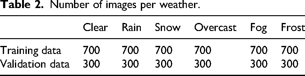
The assembled target dataset consisted of 1000 images captured at different times of day, in varying positions, and under a full range of weather conditions, including clear, rain, snow, overcast, fog, and frost conditions. Each of the original 1000 images was subject to preprocessing for normalizing their size, format, and color space. Data augmentation, such as brightness enhancement, dimming, blurring, flipping, and other image processing techniques, was then applied to obtain augmented images for extending the original preprocessed dataset to 6000 images. Representative samples from the extended target dataset are presented in Figure 7. The dataset was partitioned into 4200 images (70%) for training and 1800 images (30%) for testing. The distribution of data categorized by weather is presented in Table 2.

Representative samples from the extended target dataset obtained by data augmentation based on optical images captured under different times of day, positions, and weather conditions.
Number of images per weather.
Evaluation metrics
The present work applied the true positive (TP), true negative (TN), false positive (FP), and false negative (FN) as fundamental metrics for assessing the performance of the trained models. These basic metrics were then applied to calculate the precision, which estimates the accuracy of all positive predictions, the Recall, which represents the accuracy of TP predictions relative to all positive instances, and the Accuracy, which represents the percentage of instances the model correctly predicts out of all instances, according to the following equations.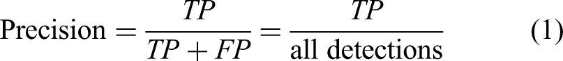


As can be seen, the general reliability of the trained model increases with increasing Precision, Recall, and Accuracy from 0 to 1. The Precision and Recall metrics were further applied to calculate the mean Average Precision (mAP) and F1Score metrics according to the following equations.

As can be seen, the mAP metric in equation (4) thoroughly evaluates a model's performance by summarizing the tradeoffs between Precision and Recall across different threshold values, while the F1Score in equation (5) balances the Precision and Recall by calculating the harmonic mean of the two. Here, higher mAP and F1Score values suggest greater model performance, and these metrics are particularly essential evaluations in situations where FP and FN results are undesirable or a tradeoff is required between high Precision and high Recall.
Fine positioning stage
The fine positioning stage begins with the delineated targets obtained as output from the coarse positioning stage shown in Figure 8. Specifically, the fine positioning stage seeks to extract the center point information of circular targets by combining edge detection and center-locating algorithms.

Positioning diagram of circular targets.
Edge detection
The Sobel 18 and Canny 19 operators are commonly applied edge detection algorithms. However, the accuracy of both of these operators is only at the pixel level, and therefore does not meet the high accuracy requirements of 3D positioning. The present work addresses this issue by first processing the edge of the circular target image using the Canny operator. Following that, precise edge detection is obtained by applying a sub-pixel edge detection method based on the Zernike moment operator. 20
The applied sub-pixel edge detection method begins by calculating the m-th and n-th Zernike orthogonal moments of a point with coordinate 

Applying the real (Re) and imaginary (Im) components of Zernike moments 

Finally, presuming that the edge pixel coordinates extracted by the Canny operator are (u0, v0), we obtain the following sub-pixel coordinates.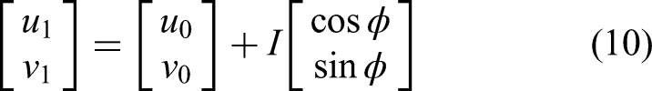
Identification of center positions
The task of obtaining the center coordinates of a circular target is complicated by the fact that a circular target appears as an ellipse on the imaging plane of the camera due to the inherent characteristics of perspective projection transformation, and the center coordinate of an ellipse requires high accuracy for extraction. To address this issue, the extracted elliptical edge is fit to the ellipse equation using the least-squares algorithm.
The overall process flow applied for extracting the center coordinates of a circular target is illustrated schematically in Figure 9. In addition, representative images associated with the different stages of the process are presented in Figure 10. As can be seen, the process begins by converting the original image into a binary image, and then applying morphological processing to enhance the edge of the target and eliminate noise. Then, the ellipse fitting process is applied to the edge detected by the Canny operator, sub-pixel edge detection is applied to the fitted ellipse, and ellipse fitting is applied again to obtain the center location of the circular target.

Flowchart of the process applied for extracting the center coordinates of a circular target.
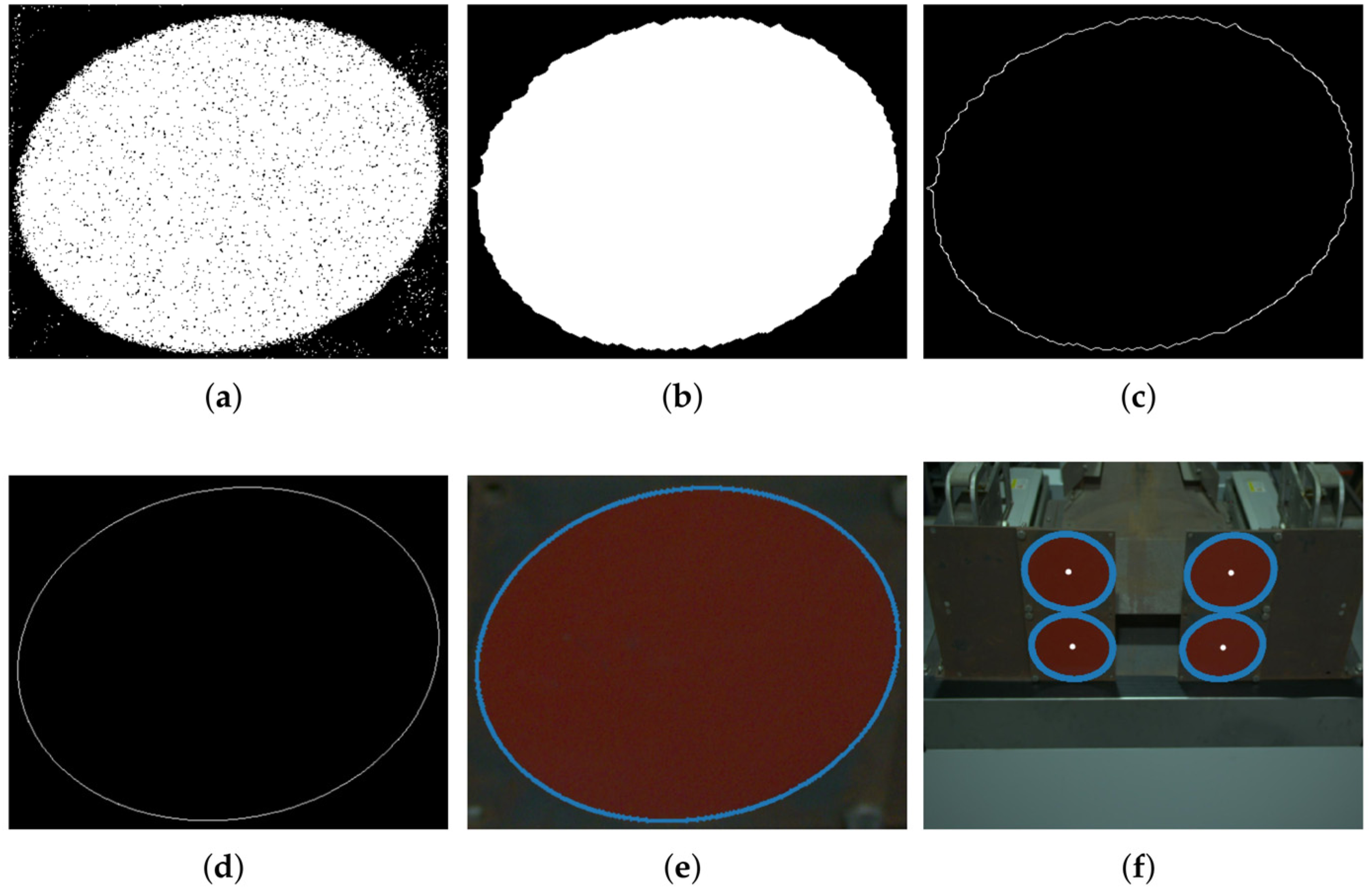
Applied procedure for obtaining the center position of a circular target: (a) binary image; (b) morphological processing; (c) Canny extraction; (d) ellipse fitting; (e) Zernike extraction; (f) center positions.
Converting center coordinates into camera coordinates based on target pose
The final task for establishing an electrical connection between the plug and socket requires that the center coordinates of targets 1, 2, 3, and 4 within the two-dimensional image denoted respectively as

Locating the center coordinates of circular targets with respect to the origin of the world coordinate system.
IPPE solution of camera coordinates
The conversion relationship between the i-th target in the pixel coordinate system and the world coordinate system can be described as follows.

Here,
The homography matrix 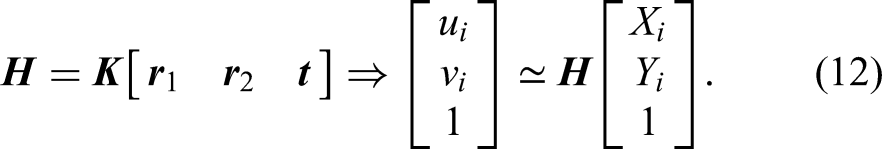
A linear system can be constructed from 4 point pairs:

The columns 

The best 
The translation vector is obtained directly from the third column of 
However, the ambiguity in the sign of the third column of 
The physically plausible solution is then selected using positive depth constraint, where, for each candidate (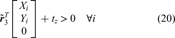
Finally, the center locations of the four circular targets in the camera coordinate system 
Locate the origin in the camera coordinate system
As discussed above, the center of the four circular targets has been selected as the origin of the world coordinate system (Figure 11). The obtained values of 
Experimental results
The prototype charging system implementation presented in Figures 4 and 5 was evaluated within Jiangsu Jianlong Electric R&D Center's experimental platform. Details regarding the computer system configuration applied for image processing and object detection are listed in Table 3. Here, the CPU operated with 14 cores at a frequency of 5.3 GHz, and the specific software framework was PyTorch 2.7.0 + cu128 along with Anaconda.
Computational system configuration.

The experimental results included an analysis of the target prediction performance of the YOLO11 network in the coarse positioning stage, and an analysis of the positioning performance of the auxiliary alignment platform in the fine positioning stage.
Coarse positioning stage results
In the training and validation experiments, the following hyperparameter values were used: 640 × 640 pixels for the input image resolution, 32 for the batch size, 0.937 for the momentum, 0.01 for the initial learning rate, and 300 for the epoch size. A stochastic gradient descent (SGD) optimizer was used because it effectively manages sparse gradients. The YOLO11 network was trained using the 4200 images in the training dataset, and a total loss of 1.07463 was obtained after 300 epochs and 2.812 h of training. The low total loss reflects a high degree of training accuracy. The accuracy with which the model identified the circular targets at each stage of training can be evaluated based on the mAP 0.5, mAP 0.5:0.95, Precision, and Recall values obtained by the model for the 1800 images of the testing dataset at each training epoch, which are presented in Figure 12. As can be seen, the individual metrics were subject to a high degree of variation during the early training epochs, but eventually reached stable plateau values.

Performance metrics obtained by the YOLO11 model for the testing dataset at each training epoch.
The Precision, Recall, and F1Score performance metrics obtained at different confidence thresholds for the fully trained YOLO11 model are respectively presented in Figure 13(a)–(c), while the Precision is plotted with respect to the Recall in Figure 13(d). As can be seen, the areas under the curves are large, suggesting satisfactory detection performance overall, and a good balance is observed between Recall and Precision. This satisfactory detection performance is further supported by the representative YOLO11 detection results presented in Figure 14 for different weather scenarios.

Performance metrics obtained for the fully trained YOLO11 model.

Representative YOLO11 detection results obtained under different weather scenarios: (a) clear; (b) rain; (c) snow; (d) overcast; (e) fog; (f) frost.
To assess the efficiency of YOLO11n in circular target detection, its performance was compared with that of advanced YOLO iterations, specifically YOLOv5, YOLOv8, and YOLOv10. The smallest variants of each algorithm were compared. Table 4 presents the performance metrics for YOLOv5n and its subsequent iterations. The comparison encompasses precision, recall, AP@50, AP@50:95, and FPS. YOLO11n exhibited a balanced performance across all metrics. The overall parameters and computational cost of YOLO11n are effectively managed, and are lower than those of other models. Furthermore, YOLO11n attained a frame rate of 172 FPS, suggesting it was appropriate for real-time circular target detection.
Performance comparison of YOLO models in detecting circular targets.

The bold values represent the optimal values.
Fine positioning stage results
These experiments were based on the relative motion between the camera and the circular targets at the end of the coarse positioning stage because the position of the circular targets and the robotic arm base is relatively fixed. The experimental accuracy was then determined by comparing the predicted coordinate displacement of the circular target in the camera coordinate system with the actual coordinate displacement of the robotic arm in the camera coordinate system. The predicted coordinates of the circular target in the camera coordinate system were obtained by coordinate transformation. In contrast, the actual robotic arm coordinate displacement was obtained through the demonstrator. The on-site experiments were conducted by translating or rotating the robotic arm sequentially in the x, y, and z directions of the camera coordinate system ten times, with a translation of 10 mm and a rotation of 3° each time, and the results are listed in Tables 5 and 6 and Figure 15.

Accuracy verification results: (a) translation coordinate results; (b) rotation angle results.
Circular target displacement positioning accuracy experiment.

Circular target angular positioning accuracy experiment.

We note from the above results that the autonomous positioning error obtained for the circular targets in the x, y, and z translation directions is within 0.8 mm, and the angular positioning errors in the Rx, Ry, and Rz rotation directions are within 0.7°. The maximum permissible deviation of the positioning of the auxiliary alignment platform was much higher than the above-mentioned values, and the high autonomous positioning accuracy ensured that the plugs could be accurately placed on the auxiliary alignment device by the robotic arm. In engineering applications, the actual requirement is that the displacement deviation of the marine plug with respect to the socket does not exceed ±5 mm, and the tilt angle is ≤ 5°. 21 During secondary positioning, the plug was moved closer to the socket by the linear motor module and the final deviation was eliminated by the displacement-limiting device. In a representative test scenario of an open laboratory environment, our system demonstrated improved positioning accuracy. Accordingly, these results suggest that the proposed method can meet the accuracy requirements of the charging system connection when dealing with challenges such as complex weather and lighting. Although its performance should be validated in a wider range of environments, the present work provides proof-of-concept and a foundation for monocular, vision-based autonomous charging systems.
Conclusion
The present work addressed the absence of cost-effective, fast, secure, and autonomous shore-based charging systems that can meet the unique conditions of shipping by proposing an innovative vision-controlled charging system composed of a robotic charging station and an auxiliary alignment platform. The vision-based system is particularly cost-effective because motion control is conducted based exclusively on images captured by a single camera, and no extra hardware is required. The system first applies the visual data captured by a single camera on the charging station to identify circular targets on the alignment platform with a rough degree of accuracy using a YOLO11 object detection model. Then, precise target coordinates are obtained from detailed edge features extracted from the rough target image, and the target coordinates are finally located within the camera coordinate system based on the target pose calculated by the IPPE algorithm. Finally, the charging process is commenced after transmitting the precise target coordinates to the robotic arm of the charging station and the plug and socket are connected. The experimental results obtained for a full-scale prototype automated charging system demonstrated that the system provides a displacement error within 0.8 mm from the precise target position, with an angular positioning error within 0.7°, which is sufficient for meeting the accuracy requirements of charging system connections in practical engineering applications. Accordingly, the experimental results demonstrate that the proposed system is reliable and efficient.
The current study is a proof-of-concept and establishes a foundation for monocular, vision-based, autonomous charging systems, although further validation in diverse environments is necessary. In future research we will investigate lightweight identification models, dynamic target tracking and prediction methods, and other approaches to achieve more efficient, cost-effective, and faster results.
Supplemental Material
sj-docx-1-arx-10.1177_17298806251404171 - Supplemental material for Automatic shore-to-ship robotic charging system with control based on monocular vision
Supplemental material, sj-docx-1-arx-10.1177_17298806251404171 for Automatic shore-to-ship robotic charging system with control based on monocular vision by Shangwei Yang, Yuanjiong Liu and Yibin Huang in International Journal of Advanced Robotic Systems
Footnotes
Acknowledgments
We thank LetPub (www.letpub.com.cn) for linguistic assistance and pre-submission expert review.
Funding
The authors received no financial support for the research, authorship, and/or publication of this article.
Declaration of conflicting interests
The authors declared no potential conflicts of interest with respect to the research, authorship, and/or publication of this article.
Data availability statement
The datasets generated during and/or analyzed during the current study are available from the corresponding author on request.
Supplemental material
Supplemental material for this article is available online.
References
Supplementary Material
Please find the following supplemental material available below.
For Open Access articles published under a Creative Commons License, all supplemental material carries the same license as the article it is associated with.
For non-Open Access articles published, all supplemental material carries a non-exclusive license, and permission requests for re-use of supplemental material or any part of supplemental material shall be sent directly to the copyright owner as specified in the copyright notice associated with the article.