
Abstract
Mobile robots are useful for environment exploration and rescue operations. In such applications, it is crucial to accurately analyse and represent an environment, providing appropriate inputs for motion planning in order to support robot navigation and operations. 2D mapping methods are simple but cannot handle multilevel or multistory environments. To address this problem, 3D mapping methods generate structural 3D representations of the robot operating environment and its objects by 3D mesh reconstruction. However, they face the challenge of efficiently transmitting those 3D representations to system modules for 3D mapping, motion planning, and robot operation visualization. This paper proposes a quality-driven mesh compression and transmission method to address this. Our method is efficient, as it compresses a mesh by quantizing its transformed vertices without the need to spend time constructing an a-priori structure over the mesh. A visual distortion function is developed to govern the level of quantization, allowing mesh transmission to be controlled under different network conditions or time constraints. Our experiments demonstrate how the visual quality of a mesh can be manipulated by the visual distortion function.
1. Introduction
Recently, mapping has been a very active research area in Simultaneous Localization and Mapping (SLAM) [1] for robotic applications. 3D mapping and reconstruction [2, 3] produce structural 3D geometric representations for robot operating environments and their objects, providing comprehensive inputs for motion planning to enhance results and guide robot navigation and operations more appropriately. The accuracy of such processes depends on appropriate camera pose estimation [4]. One popular representation of such 3D mapping is meshes, which may entail large data size, causing performance issues in passing environment and object representations to system modules for 3D mapping, motion planning, and robot operation visualization. Such representations may require continuous updating when a robot is exploring an unknown or dynamic environment.
Although there exist many mesh compression and transmission methods [5, 6, 7] that seek to address the above challenges, most of these require structures to be built on top of 3D meshes before they can be transmitted. This is not favourable to robotic applications, where the environment and object representations may be dynamically generated and updated during run-time. In such applications, the requirement of constructing a-priori structures will repeatedly cause delays in obtaining timely environment and object representations, limiting capacity to produce motion plans or support multi-robot collaboration.
This paper proposes a quality-driven mesh compression and transmission method. Our main idea is to compress a mesh by quantizing its transformed vertices without constructing an a-priori structure on top of it. A visual distortion function is developed to govern the level of quantization, allowing a robot application to adjust the data rate of mesh transmission according to network conditions or time constraints. Our experiments demonstrate how the visual quality of a mesh can be manipulated by the visual distortion function. The paper's main contribution is to formulate the relationship of the mesh quantization level and the number of anchors with the visual distortion error and the low-frequency error. This contribution includes:
Development of a fitting function to formulate how low-frequency error (LFE) responds to a change in the distribution density of anchors,
Explanation of the behaviour of visual distortion error (VDE) under different mesh quantization settings and when different numbers of anchors are introduced to reconstruct a mesh, and
Introduction of a concise method to represent the distribution density of anchors and a breadth-first search method to incrementally keep records of anchors with different distribution densities, such that different numbers of anchors can be efficiently added to support fast quality control for a reconstructed mesh during run-time.
Our method allows a user to request a mesh to be compressed and transmitted according to some run-time constraints, such as computation or network resource limitations.
The rest of the paper is organized as follows. Section 2 outlines related work. Section 3 depicts the technical aspects of our method. Section 4 presents the formulation of the visual distortion function based on visual distortion error (VDE) and low-frequency error (LFE). Section 5 discusses our experimental results. Section 6 concludes the paper and describes future work.
2. Related Work
Mesh compression and transmission have a wide range of applications in computer graphics or network systems. Here, we discuss the major developments and relevant challenges in the context of robotic applications.
2.1. Mesh Transmission
Early work supporting efficient mesh transmission was carried out on progressive meshes [8], transforming a 3D mesh through edge-collapse and vertex-split operations into a streaming format comprising a base mesh (a very simplified version of the input 3D mesh) and a list of refinement records (an ordered list of geometric details of the 3D mesh built on top of the base mesh). An application can reproduce a 3D mesh with a certain level of quality by receiving the base mesh and a chosen number of refinement records. Many works have extended progressive meshes to improve data-encoding efficiency and introduce flexibility and independence to the choice of refinement records for mesh transmission and rendering.
Later, some 3D-mesh-specific data-transmission protocols were developed to support adaptive mesh rendering (displaying part of a 3D mesh based on user interests or a 3D mesh with a selective quality to fit network or rendering requirements). For instance, the On-Demand Graphical Transport Protocol (OGP) [9] organized a mesh into a tree structure and packed tree nodes into data packets for transmission according to sub-tree ordering and tree-node dependency. It also retransmitted tree nodes when data loss occurred. To improve the scalability of 3D mesh transmission among clients and servers, [10] developed a coding scheme to encode the tree structure of view-dependent progressive meshes. Such codes make it possible for a receiver to identify and initiate requests to obtain further required refinement records from a server. [6] supported error resilience for transmitting progressive meshes over unreliable networks. The author constructed a non-redundant directed acyclic graph and its sub-graphs to organize vertex-split records into minimal-dependency groups for mesh transmission. Alternatively, Geometry Images [11] encoded 3D meshes as a regular image through parameterization and mesh cutting. Generic image-based methods could then be adopted to transmit and compress meshes, although a wavelet-based method was chosen in that paper. [7] proposed a content prioritization method by extending object scope and viewer scope to determine the required quality for geometric transmission. This method assumed that all geometric primitives are pre-organized into progressive-mesh-like structures. Clearly, the main limitation of the above methods is the requirement of constructing a-priori structures over meshes. In many cases, this process is time-consuming, and it is particularly inappropriate for robotic applications with unknown or dynamic environments, due to the requirement for continuous reconstruction or updating of 3D meshes.
2.2. Mesh Compression
Mesh compression is a technique to reduce the data size of a mesh, which complements mesh transmission, making it more efficient. A lot of work has been done in this area [5]. The main approaches to compress a mesh are to reduce the data size of mesh geometry or connectivity. Compressing mesh connectivity is typically done by traversing and defining new numbering of the configuration of mesh elements (i.e., mesh topology). Existing methods [12] include indexed face set, triangle strip, spanning tree, layered decomposition, and a valence-driven approach. Compression results are usually tied up with a particular state of mesh configuration and become invalid when there is any change to this configuration.
Recently, major efforts have been made in geometric compression [5], because in most cases mesh geometry involves bigger data sizes than mesh connectivity. Performing compression in the geometric domain will obtain a better gain in compression ratio. Vertex quantization is a simple approach that encodes mesh vertices with a low number of bits or certain concise geometric means, such as angles. This approach does not rely on construction of an a-priori structure over a mesh. However, it introduces high-frequency error, which is highly noticeable. An alternative way to reduce vertex data size is by prediction, which stores a vertex according to its difference to some reference vertices, reducing the entropy by exploiting the correlation between neighbouring vertices. Re-computation may be required if there is any change in the reference vertices.
In section 2.1, we have discussed mesh transmission methods. In practice, progressive meshes [8] or their extensions are usually also considered lossy compression methods, as they usually reproduce a mesh by removing some geometric details. As discussed above, they require the construction of a specific mesh structure to facilitate the choice of geometric details for reconstructing a 3D mesh. Progressive-mesh-like methods usually arrange mesh elements with a pre-defined sequence for transmission. If a specific part of a mesh is required, we may still need to spend time transmitting most or even the entire set of mesh data before that specific part can be obtained. This behaviour is particularly unsuitable for the real-time requirements of robotic applications. To address this problem, [13] developed a cluster-based random accessible compression scheme, which constructed and compressed independent clusters of a constant number of mesh triangles, as well as their first referenced vertices. The random access to mesh elements was achieved by vertex-to-cluster mapping with the help of cluster caching and on-demand connectivity construction. [14] provided random access to mesh elements by partitioning the mesh bounding box into a hierarchical structure, namely nSP-tree, which is composed of SP cells encoded independently to comprise connectivity and geometric information. Again, this set of methods still relies on the construction of a-priori structures, although it is feasible to only construct structures for local mesh elements with these random-access methods, reducing the overhead.
2.3. Robotic Applications and Issues of 3D Mapping and Reconstruction
Mobile robots [15] have many applications, including environment exploration, search and rescue, assistance for disabled or elderly people, edutainment, and home and industrial automation. Simultaneous localization and mapping (SLAM) [1] is a key component of robotic systems for the construction of a representation of the robot's operating environment. The comprehensiveness of such a representation will affect the accuracy of motion planning, the ability of well-reconstructed environments to support robot collaboration, and the quality of human-robot interaction. If an environment is unknown or dynamic, SLAM becomes challenging due to the unavailability of landmarks or known features while fulfilling real-time performance requirements.
3D mapping and reconstruction provides a useful solution for representing robot operating environments and their objects, as it produces structural 3D geometric information, improving motion-planning results for guiding robot navigation and operations. Early attempts in this area were presented by [16], who constructed flat surfaces of an environment by performing region growing and surface merging on the collected 3D points from range scanners. [2] applied a Markov Random Field to integrate high-resolution image data and low-resolution range data for recovering range data at the same resolution as the image data. [3] constructed 3D mapping by decomposing the collected point cloud into octree cells, followed by a merging and refinement process and the adding of semantic labels. In practice, while a robot is exploring an environment, the captured data about the environment may have a lot of redundancy. Appropriate methods, such as those presented in [17, 18], may be adapted to reduce such redundancy. However, complications are presented if multiple robots are involved in a robotic application. [19] proposed a cooperative localization method allowing a moving robot to explore the environment by making use of stationary robots as landmarks to assist in mapping and reconstruction, where the error of tracker measurement and the uncertainty in the position of a stationary robot were taken into account.
Efficient transmission of environment representations is crucial to robotic applications. For instance, [20] described VR (virtual reality) interfaces for controlling complex robotic mechanisms in planetary-surface exploration missions. The author showed that the large data size of photo-realistic terrain models and range maps imposed challenges for data transmission, particularly relating to latency, unreliability, and limited-bandwidth issues with the communication link among different sub-systems and the user interface of a remote robotic system. There exist different robotic applications. [21] investigated environment exploration and 3D mapping in urban search and rescue, where environments are lacking a-priori information about landmarks and GPS may not be able to assist robot positioning. The method identified keypoints from 2D images and 3D depth images captured from the environment by using the SIFT algorithm, which is able to determine distinctive invariant features from images. It then clustered the keypoints and performed matching to define landmarks. [22] demonstrated an MR (mixed-reality) robotic application allowing a robot to perform simulation in a real environment with virtual objects or hazards, which is useful for studying different real situations.
3. Our Method
We have developed a simple and quality-driven mesh compression and transmission method, which does not require an a-priori structure to be built on top of a mesh. This avoids introducing dependency or imposing any access sequence constraint on mesh vertices, and allows a robotic application to freely choose whether to compress or transmit either an entire mesh or only its parts. This is critical, because robotic applications may involve only partial environment representation (literally is a mesh part) during run-time, which is incrementally built and updated according to robot exploration. In addition, this feature also allows a robotic application to choose whether to compress or transmit only a mesh part when the network or processing resources are limited.
Figure 1 presents an overview of our method, which is geometry-based. We compress geometric coordinates (mesh vertices) by performing quantization on their Laplacian transformation and tuning their resultant quality. We control mesh quality by adjusting the Visual Distortion Error (VDE) and Low-Frequency Error (LFE). Mesh connectivity information (topology data) is sent separately to the client based on [23] to facilitate mesh reconstruction.

Method overview
3.1. Mesh Quality
Quantization is a technique to represent data with a selected quality using a reduced number of bits. Applying quantization to compress mesh vertices is straightforward. However, it will induce high-frequency error, which is not favourable because it becomes noticeable to humans. [24] addressed this problem by applying quantization to the Laplacian transformations of mesh vertices, turning the resultant error into low-frequency error. Such a Laplacian transformation could be properly produced only if there existed some anchors, namely vertices without quantization, in the compressed mesh. The author also proposed a metric to measure the visual quality of a compressed mesh in terms of its global and local geometric error. Unfortunately, it is difficult to apply this method in real applications as it provides no mechanism to control the amount of quantization and the number of anchors for mesh compression. Therefore, we conducted an empirical study to investigate how the mesh quality relates to the amount of mesh quantization and the distribution of anchors, developing a quality-driven mesh compression and transmission method.
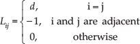
The quality of a compressed mesh can be accurately evaluated based on its global and local geometric error. As shown in Equation 1, the global geometric error can be determined by measuring the vertex difference between the compressed and the original meshes. Since it measures the geometric change of a mesh after compression, it essentially represents the low-frequency error (LFE) induced by mesh compression. We denote this error as Mq. Alternatively, the local geometric error measures the difference between the local regions of the compressed and the original meshes, determined by Equation 2. This essentially represents the extent to which local features of a mesh are changed after compression such that the change is visible to users. We regard this as the visual distortion error (VDE), denoting it as Sq.


where vi represents a vertex of a mesh with n vertices, and
3.2. Mesh Compression through Quantizing the Laplacian Transformation

where A and D are the adjacency matrix and diagonal matrix, respectively, and
The aim of our method is to exploit the low-frequency error produced from quantizing δ -coordinates to provide a quality-driven mesh compression method. Simple Laplacian transformation, which is evaluated by computing the difference between a vertex and its neighbouring vertices, is already sufficient to produce δ -coordinates and is computationally efficient. Therefore, we do not consider other variants of Laplacian transformation operators or other spectral transformation methods, which might be computationally more expensive.

Constructing the rectangular Laplacian matrix with two anchors (denoted in red)
3.3. Mesh Transmission Workflow
During run-time, a receiver may request transmission of a mesh from a sender by specifying the VDE and LFE levels. The sender will then perform the following operations:
Perform Laplacian transformation on mesh vertices, producing “δ coordinates”.
Quantize δ coordinates according to the receiver's chosen VDE level.
Determine the number of anchors based on the receiver's chosen LFE level, with the help of an LFE fitting function. Identifying the actual anchors to support mesh reconstruction at the receiver will be facilitated by the BFS picking method.
Refine the LFE computation by adding extra anchors with the greedy picking method.
After processing the geometric data, we compress the mesh and send the resultant δ coordinates and anchors to the receiver. The mesh topological data will be transmitted based on [23].
The details of operations 3 and 4 will be discussed through sections 4.2.2 to 4.2.4.
4. Mesh Quality Control: VDE and LFE
In this section, we depict how the Visual Distortion Error (VDE) and the Low-frequency Error (LFE) are formulated empirically.
4.1. Visual Distortion Error
The Visual Distortion Error (VDE) evaluates the mesh's visual quality according to the user's perception. We have conducted experiments to investigate the main factors affecting such an error. Through our experiments, we found that VDE is both influenced by the number of anchors introduced to a reconstructed mesh and the number of bits used for quantizing a mesh.
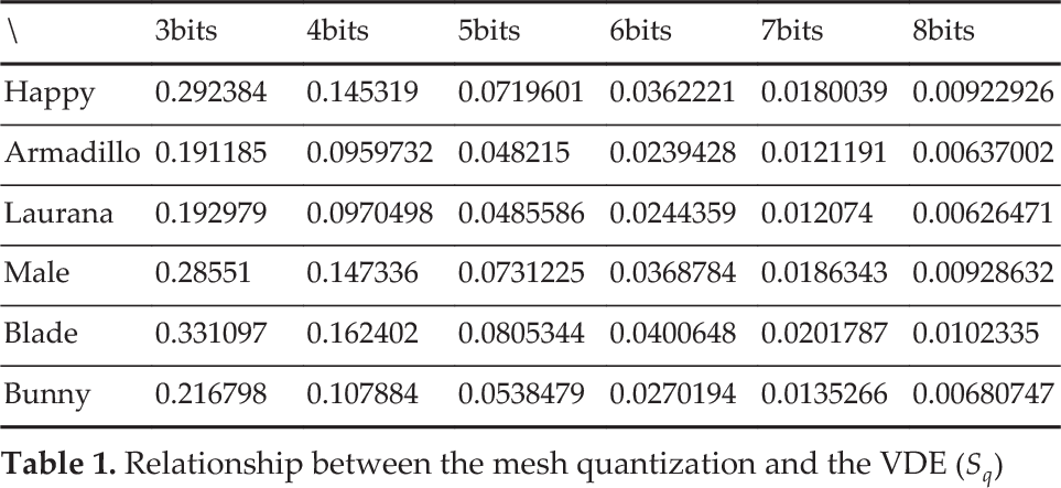
Figure 3 shows how the VDE, denoted by Sq of the five-bit quantized Armadillo model (ref. Figure 8(b)) was influenced by the introduction of different numbers of anchors. It was found that the VDE changed dramatically when introducing around 10 or fewer anchors. Further introduction of anchors did not improve the VDE of the model. We also conducted experiments on a set of mesh models to investigate how quantization influenced the VDE of a mesh. The results are shown in Table 1. The table shows that the VDE of different models was generally reduced by half when one or more bits were allocated for quantizing the models.
Relationship between the mesh quantization and the VDE
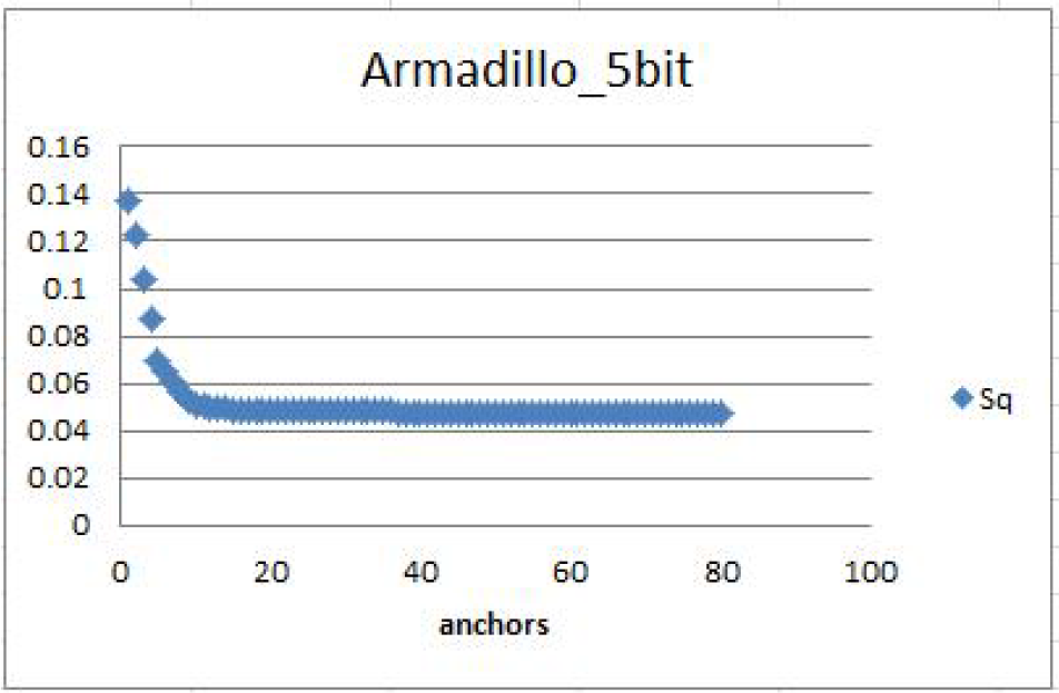
Relationship between the number of anchors introduced and the VDE
4.2. Low-Frequency Error
Low-frequency error (LFE) measures the geometric difference between the compressed and the original mesh, globally. We have investigated how this error is influenced by the number of anchors and the number of bits for quantization, developing a fitting function to allow an application to determine the required number of anchors to be introduced to a mesh based on a given LFE. We have also developed a breadth-first search (BFS) and a greedy pick method for identifying the actual anchors to be introduced in a mesh.
4.2.1. Formulating Anchor Distribution Density
When introducing anchors to a mesh, we assume they will be added evenly to maximize the gain in mesh quality. The distribution density of anchors can then be formulated by a parameter v. If a mesh with N vertices has k anchors, then the number of non-anchors is

A sample mesh with anchors (red) and non-anchors (quantized vertices). The purple points indicate the vertices most distant from an arbitrary anchor.
4.2.2. Incremental Anchor Recording
After determining the appropriate number of anchors, it is critical to efficiently identify the actual anchors to be introduced to a mesh in order to support real-time applications. We have therefore developed a breadth-first search (BFS) method to help an application to store anchors with different distribution densities in a set of different containers. Consequently, appropriate anchors can be quickly picked out according to a requested LFE.
Our breadth-first search (BFS) method operates as follows. We first pick an arbitrary vertex to be an anchor. A breadth-first search operation is then performed around this anchor based on mesh connectivity, which records the geometric distance between a sought vertex and the anchor as a depth, denoted by v. The sought vertex with the largest v value is selected as the second anchor, and used in the performance of the same BFS operation again. A sought vertex will be assigned the newly evaluated v if it was assigned a smaller v value in previous search operations. The above operations are repeated to generate more anchors. As the number of anchors increases, the evaluated v of a searched vertex will generally decrease. When the largest v value reaches a threshold Vu, all selected anchors are stored in a container
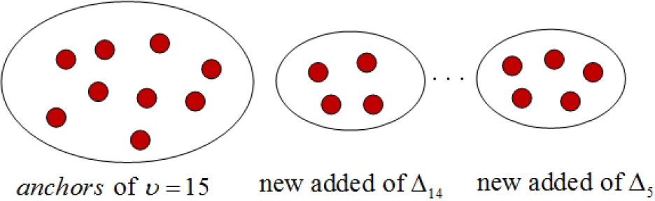
Incremental Anchor Recording through containers
4.2.3. Relationship between Anchor Distribution Density and LFE
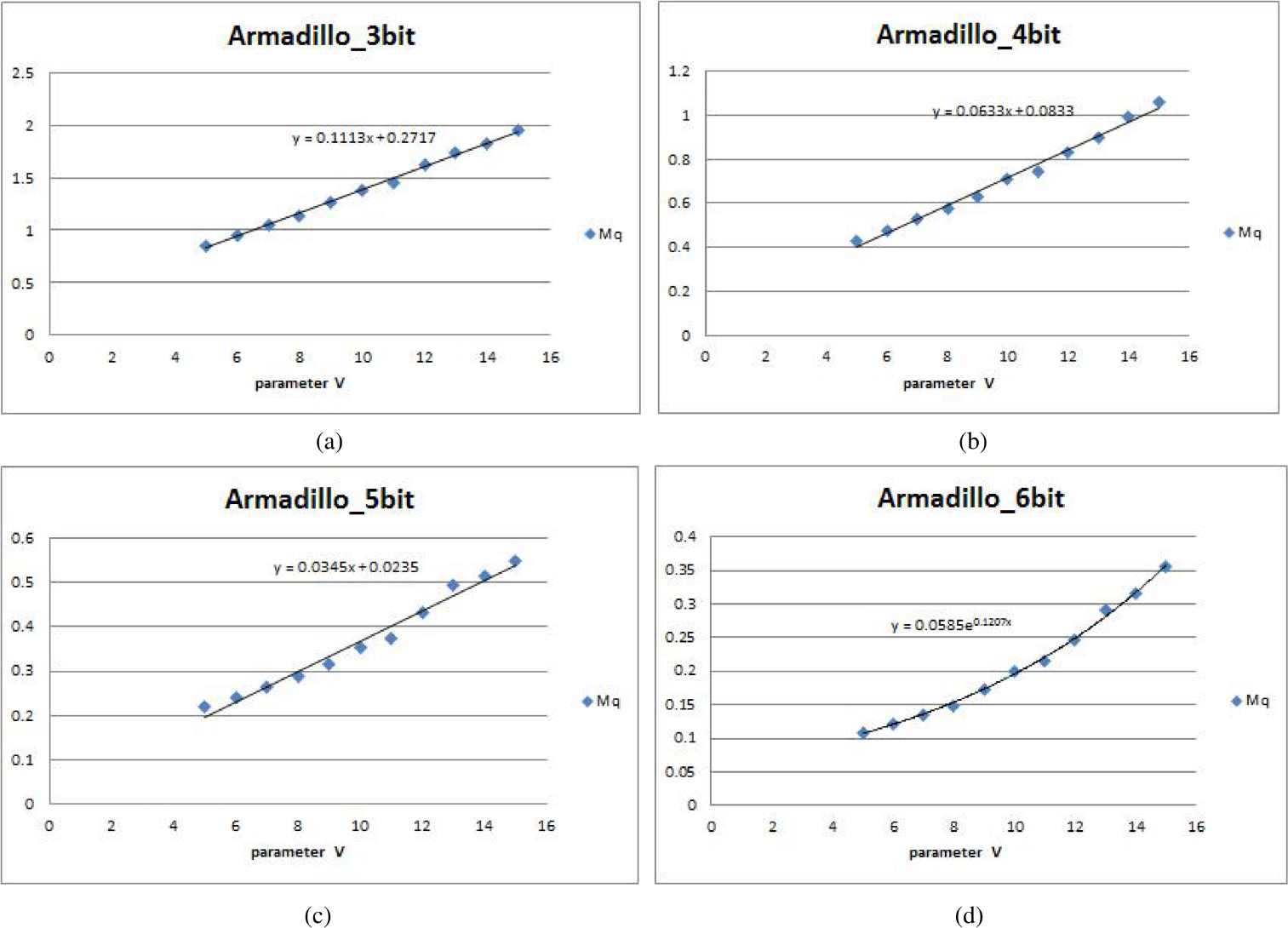
Increasing the number of anchors can effectively reduce the LFE of a reconstructed mesh. We conducted experiments to investigate this relationship and develop a fitting function to model the relationship between anchor distribution density (parameter v) and LFE (denoted as Mq). Figure 6 demonstrates this relationship through the Armadillo model, as quantized using different numbers of bits. It can be seen that the relationship was quite linear when the model was quantized by a small number of bits. This was because adding more anchors effectively enhanced the mesh quality by reducing the LFE. In contrast, the relationship became exponential when the number of bits used for quantization became large, because adding more anchors after this point no longer effectively contributes to the reduction of the LFE. Based on this finding, a fitting function
When δ coordinates are quantized by three bits, four bits or five bits, the fitting function
When δ coordinates are quantized by seven bits or eight bits, the fitting function
When δ coordinates are quantized by six bits, the fitting function
The relationship between LFE
4.2.4. Controlling LFE by the Fitting Function
When transmitting a 3D mesh, we select v for two different parameters and compute their corresponding low-frequency errors
When δ coordinates are quantized by three bits, four bits or five bits, as the fitting function
When δ coordinates are quantized by seven bits or eight bits, the fitting function
When δ coordinates are quantized by six bits, the fitting function
After we obtain the parameter v as above, the actual LFE
5. Results and Discussion
In this section, we analyse how the introduction of anchors influences the LFE of a reconstructed mesh. We also compare reconstructed meshes with different VDE and LFE.
In our experiment, we quantized the δ coordinates of mesh models from three bits to eight bits, and used 12 bits to store anchors. Since only a small portion of vertices were selected as anchors (about 0.2% to 1.5% of the δ coordinates), the data sizes of anchors are comparatively very small.
By increasing the quantization accuracy of δ coordinates, the representation of the fitting function
When the quantization accuracy of δ coordinates is fixed, the contribution of each newly added anchor to reducing LFE decreases when the number of anchors increases. Figure 7 shows examples to prove this. In Figures 7(a) and 7(b), the Laurana model was quantized with six bits. Figure 7(a) shows the fitting function
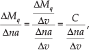
where C is a constant, and the number of anchors is denoted by

(a) shows how Mq varied with parameter v when the Laurana model was quantized by six bits; (b) shows how the percentage for anchors varied with parameter v on the same model. (c) and (d) report the results obtained from performing the same set of experiments on the bunny model.
Table 2 shows the results for different mesh models when quantized with four, six, and eight bits, respectively. We assigned either 19 or 38 anchors to these models for each quantization level. The results showed that the level of quantization has a great impact on both Sq and Mq. Of course, the size of the reconstructed mesh data will increase if we raise the level of quantization. Although adding anchors has only a small effect on Sq, it has a great effect on Mq. Since the required data size of storing anchors is typically small, adding anchors to control Mq is a feasible method.
Influence of the quantization bits and the number of anchors on VDE Sq and LFE Mq

Figure 8 compares the visual quality of three mesh models, which are transmitted with different visual errors. When the quantization level is increasing, the reconstructed mesh model is visually more similar to the original model. Our method still produces visually good results even if a mesh is quantized by a small number of bits, e.g., three or four bits. Figure 9 shows the reconstructed model with different low-frequency errors. When the number of anchors increases, the low-frequency error decreases, and the vertices of the reconstructed mesh will be geometrically closer to the corresponding vertices of the original mesh.

(a) shows how Mq varied with parameter v when the Laurana model was quantized by six bits; (b) shows how the percentage for anchors varied with parameter v
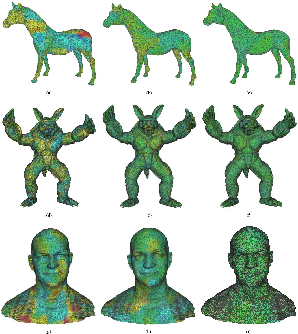
Reconstructed meshes of the Horse, Armadillo, and Male models (top, middle, bottom row) with different LFEs, which are 0.6, 0.4, and 0.2, respectively (from left to right). For the reconstructed meshes, each vertex was coloured according to LFE
6. Conclusion
In this paper, we have proposed a quality-driven mesh compression and transmission method. This method is useful for robotic applications. When such applications require environment exploration, particularly in dynamic or unknown environments, they may suffer from a performance issue when transmitting environment representations (here, 3D meshes) that they construct, since these are typically either partial or dynamic, and need to be updated continuously. Although mesh compression is a sensible way to improve data-transmission performance, the main concern in applying mesh compression is the need to construct an a-priori structure, which may be time-consuming and become invalid whenever the mesh is updated.
Our method is free from the above issues and can also be applied to locally compress only the updated mesh part. In addition, our method offers a simple mechanism to control the visual quality of a compressed mesh. All these features match well with the requirements of robotic applications, where frequent mesh updating is required and the resource availability for mesh transmission may change over time.
To demonstrate our work, we have conducted experiments to depict mesh quality against different settings and visual errors. In our future work, segmentation on the large model will be taken into consideration. This might enhance the computing efficiency, although the border between segmentations needs careful handling. We will also investigate how the compression ratio affects path-planning accuracy in robotic applications.
Footnotes
7. Acknowledgements
This work was partly supported by the National High Technology Research and Development Program of China (863 Program, Grant No. 2013AA013701), the Zhejiang Province Natural Science Foundation for Distinguished Young Scientists (Grant No. LR12F02001), the National Natural Science Foundation of China (Grant Nos. 61170214, 61472363, 61170098) and Zhejiang Province Natural Science Key Foundation (Grant No. Z1101340).