
Abstract
This paper presents a dynamic stability analysis method for a trotting quadruped robot on unknown rough terrains, which is based on the Lyapunov theory of a switching system. Firstly, the dynamical model of a trotting quadruped robot is built as a nonlinear switching system. In the stance phase, the dynamical model of a body and two stance legs is approximated as a compound model including a seven-link mechanism and a linear inverted pendulum. Furthermore, as a result of the switching process, the trotting quadruped robot becomes a non-autonomous system. Secondly, a contact force distribution/control strategy is proposed, based on adaptive sliding mode to guarantee the position and orientation of the seven-link mechanism asymptotically stable in the stance phase. With the proposed strategy, a common Lyapunov function is designed in order to validate the uniform asymptotic stability of the body's height and orientation variations. Then, the landing positions of the swing legs are calculated, based on the linear inverted pendulum model in order to make the horizontal position error of the robot converge to a bounded region. Finally, quadruped trotting experiments are performed in order to validate the effectiveness of the proposed methods.
Keywords
1. Introduction
Trotting quadruped robots have been investigated by many researchers in the past few decades. In a process of dynamically balanced trotting locomotion, maintaining stability of the body is a necessary condition. In recent years, several successful quadruped robots have been developed. For example, Big Dog [1, 2], AlphaDog [3] (Boston Dynamics) and HyQ [4] (IIT) have strong dynamic stability and robustness when trotting on unknown rough terrains.
Generally, the stability analysis methods for the trotting quadruped robots can be divided into three sub-phases: i) the static stability analysis method, ii) the limit cycle method, iii) the Lyapunov method. Much of robotics literature validates the effectiveness of those methods experimentally. However, each of these approaches has its limitations.
The static stability analysis method establishes a conventional stability criterion for the walking robots. If the Center of Pressure (CoP) is inside the support polygon, then the robot is statically stable [5]. Kalakrishnan and his colleagues proposed a trajectory generation based on CoP in order to achieve locomotion over rough terrains [6], Furthermore, considering the velocity and acceleration of the robot, Zero Moment Point (ZMP)-based methods were used to calculate the stability margin and generate physically viable quadruped locomotion trajectories [7, 8]. However, in most cases, the support polygon of a trotting quadruped robot is a line. Therefore, the trotting quadruped robot is a statically unstable system, a factor that will be explained in Section 2. Thus, the methods mentioned above are inapplicable for analysis of the trotting quadruped robots' dynamic stability.
The limit cycle method is a popular choice for analysing the dynamic stability of the walking robots, and its core is transforming the stability of the limit cycle into the stability of the fixed point by establishing a Poincare Return Map (PRM) [9, 10]. However, the dynamical model of a trotting quadruped robot is too complex to allow an analytical solution. Therefore, for a trotting quadruped robot, a PRM could only be established via simulation or experimental regulation, unless it is based on the reference models [11–14]. Many researchers simplify a trotting quadruped robot as a SLIP model [15–18]. However, the statically stable components of the body position along the stance line are neglected.
Based on the gait characteristics, the trotting quadruped robot is a nonlinear switching system with a fixed switching cycle. Daniel Liberzon and his colleagues have secured many theoretical achievements regarding the stability analysis of switching system by using the Lyapunov method [19–22]. However, little of the literature applies the results to analysing the dynamic stability of the walking robots, because it is difficult to construct appropriate Lyapunov functions for proving the uniform asymptotic stability of the body's position and orientation. Zhi Liu et al describe a biped robot as a switching system [23], but do not analyse the dynamic stability of the robot.
In the light of the discussion above, the contributions of this paper take the form of two parts. 1) By distinguishing the statically stable subsystem from the statically unstable subsystem, the dynamical model of the robot in the stance phase is built as a compound model including a seven-link mechanism and a linear inverted pendulum model. Furthermore, the integrated process of trotting is described as a nonlinear switching system, which reflects the dynamic characteristics of a trotting gait more explicitly. 2) A contact force distribution algorithm, based on adaptive sliding mode is designed to resist the disturbance caused by the landing impact forces. With the proposed contact force distribution/control strategy, the dynamic stability of the trotting quadruped robot is analysed based on a common Lyapunov function.
This paper is organized as follows: Section 2 is devoted to building the dynamical model of the trotting quadruped robot and explaining its statically unstable characteristics. The control strategy and dynamic stability analysis are described in Section 3. Then, experimental results are thoroughly evaluated in Section 4. Finally, conclusions are drawn in Section 5 via the final discussions.
2. A switching dynamical model of a trotting quadruped robot
2.1 A dynamical model of a trotting quadruped robot in the stance phase
A pair of diagonal legs is driven constantly during the trotting process. The stable trotting gait is achieved by periodically switching the diagonally legs between the stance phase and the swing phase. Without loss of generality, in the following analysis, the Left Rear (LR) leg and the Right Front (RF) leg are set in the swing phase, while the Right Rear (RR) leg and the Left Front (LF) leg are set in the stance phase. In the other case, the model is similar to the one described here.
A coordinates Σo is defined as follows: The origin attaches to the midpoint of the stance line, the X-axis is along the sagittal velocity direction of the robot, the Y-axis is in the opposite direction to that of the gravitational acceleration and the direction of the Z-axis accords with the right-handed rule.
Based on Lagrange equations, the dynamical model of a trotting quadruped robot in the stance phase is given by (1) [24]:

where q1 = [q11,6×1 q12,8×1]
T
q11 =[X Z Y α β γ]
T
is the position and orientation of the body in Σo, q12 = [θ1_
LF
θ2_
LF
θ3_
LF
θ4_
LF
θ1_
RR
θ2_
RR
θ3_
RR
θ4_
RR
]
T
is the joint angles of the stance legs and the subscript 1,2,3,4 indicate the ankle joint, knee joint, sagittal hip joint and lateral hip joint, respectively.
The dynamical model could be resolved into the following two equations:


It can be obtained that J11 is not full rank by calculating its determinant, which means that the position and orientation of the body are not completely controllable in a single stance phase. Therefore, the trotting quadruped robot is statically unstable, except while it is at the equilibrium point.
In order to distinguish the statically stable components and the statically unstable components of q11 in (2), two dimension-reduction transformations are constructed as following:


By synthesizing (2) and (4), the dynamical model for q˜11 can be obtained:

where
Considering that the height and orientation angles of body are controllable in (6), we assume that

where g is the gravitational acceleration.
From (7), it can be seen that, along the direction perpendicular to the stance line in horizontal plane, the trotting quadruped robot could be approximated as a linear inverted pendulum. The analytical solution of a linear inverted pendulum model is as follows:

By synthesizing (6) and (7), a trotting quadruped robot can be approximated as a seven-link mechanism and a linear inverted pendulum model, as shown in Fig.1.

Approximate model of a trotting quadruped robot
Correspondingly, while the LR leg and the RF leg are in the stance phase, and the RR leg and the LF leg are in the swing phase, the dynamical model of the body can be described via the following equations:


where
2.2 Switching model
During quadruped trotting, two pairs of diagonal legs switch periodically between the stance phase and the swing phase. Synthesizing the switching process, the dynamical model of a trotting quadruped robot is as follows:


where


where
The switching dynamical model has the following properties, which can be exploited to facilitate the control strategy design and dynamic stability analysis.
The dynamical model of the trotting quadruped robot in the stance phase is an autonomous system, but the switching dynamical model is a non-autonomous system, because (14) includes the time variation. Therefore, for a trotting quadruped robot system, LaSalle's invariance principle is inapplicable.
The input of the switching model contains two parts: joint torques (τ12, τ22) and Xil+. Xil+ indicates the landing position of the swing leg. Simultaneously, it is the initial position of the linear inverted pendulum model, and the contact forces are intermediate variations in the switching model.
J˜11 and J˜21 are 5×6 matrixes, while Fe1 and Fe2 are 6×1 vectors. Therefore, another virtual constraint is required in order to calculate a set of unique desired contact forces for stance legs from u1 or u2.
3. Control strategy and dynamic stability analysis
3.1 Control strategy
On the rough terrains, the landing velocities of swing feet may not be zero and impact forces would be engendered, a state that causes impulse disturbances for the position and orientation tracking of the robot. As a result, two bounded disturbance vectors are added to the dynamical model in order to mimic this influence. Taking the LF leg and the RR leg in the stance phase as an example, (6) and (3) can be rewrited as follows:


where || ρ11|| ≤d1, || ρ12|| ≤d2, d1, d2 are positive constants.
In this section, a double-loop control strategy is proposed for performing the contact force distribution and control. During quadruped trotting, the contact forces between the stance feet and the ground are the only external forces that act on the robot, except for gravitation, if no other forces are exerted. Therefore, the contact forces are the important intermediate variations, which are distributed and controlled in order to connect the outer-loop and the inner-loop. In the outer-loop, the desired contact forces of the stance legs are calculated by using the pose error of the body and a virtual constraint. In the inner-loop, the joint torques of the stance legs are adjusted to make contact forces track the desired values. The control cycle of the outer-loop is 10 times that of the inner-loop. The configuration of the proposed control scheme is shown in Fig. 2.

Control scheme
1. Contact force distribution algorithm
In order to decrease the influence of the disturbance in (17), a contact force distribution algorithm based on sliding mode is designed. The setting-tracking error
Setting
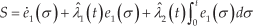
where


where

Theorem 3.1: For the system (17) with the sliding surface defined by (19), the tracking error e1 satisfies
Proof:
Setting

Differentiating (26) with respect to time:

Taking the time derivative of the sliding variation defined in (19):

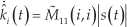
Substituting (20)-(25) into (28):

where
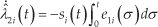
Substituting
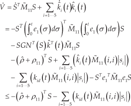
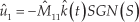
Therefore, if kid satisfies the following condition:
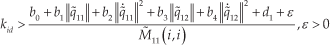
Then
Based on the conclusion of section 2, a virtual constraint is needed to make J˜11 reversible. In this section, the virtual constraint is set as a desired zero interactive force between the stance feet, as follows:

where [xe_LF ye_LF ze_LF] T ([xe_RR ye_RR ze_RR]) T is the foot position of the LF (RR) leg in Σo.
Synthesizing (20) and (32), the desired contact force can be calculated as follows:

where
2. Contact force control algorithm
As shown in (18), the model from τ12 to Fe1 is a zero-order system, therefore the contact force controller is designed as following:

where θ LF (θ RR ) is a linear restriction of the LF (RR) leg's joint angles. The redundant joint could be used for optimizing the maximum length of the leg [31–33]. In this paper, the linear restriction is the ankle joint angle, which equal to the knee joint angle of every leg. In addition, it has been proven that the static error can converge to zero by using a PI controller[29], even for existing bounded disturbances.
3.2 Dynamic stability analysis
Lemma 3.1: If both subsystems (
Proof:
Because V(x) is both positive definite and radially unbounded, there exist two class K∞ functions X1, X2 such that V(x) satisfies:

V(x) satisfies (33) and V̇(x)<0, therefore, the switching system is uniformly asymptotically stable [30].
Theorem 3.2: For the switching system (11)- (14), with the double-loop control strategy ((20–25), (33) and (34), while the RF leg and the LR leg are in the stance phase, the strategy is similar to the equations above), the height and orientation angles of the body are uniformly asymptotically stable during quadruped trotting.
Proof:
Based on the conclusions in Section A, it is obvious that the tracking errors of q˜11 and q˜21 can converge to zero with the proposed double-loop control strategy as t → ∞. Therefore, in the stance phase, q˜11(1, 1) (q˜21(1, 1)) can converge to a bounded region, satisfying |q˜11(1, 1) | <ζ (|q˜21(1, 1) |<ζ) ζ >0. Then a common Lyapunov function is designed as follows:

where
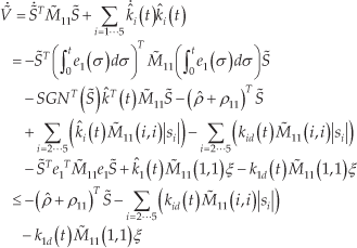
Therefore, if kid satisfies the condition (31), then
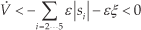
When the RF leg and the LR leg are in the stance phase, similar calculation produces the same result (
Now, we design the landing positions of the swing legs to guarantee that the horizontal position error converges to a bounded region, and the time sequence in the adjacent two stance phases is shown in Fig. 3.

The time sequence in the two adjacent stance phases
As shown in Fig. 3 (a),X2 l +(t1) is designed at t0, making the tracking error ex = X - Xd and ez = Z - Zd converge to zero at t2.
At t1, with the proposed double-loop control strategy and model (8), the horizontal position of the body is calculated as follows:


where
By synthesizing (39) and (40), X (t1) and Z(t1) can be solved. Furthermore,

As is similar to the previous stance phase, (40) could be achieved at t2:

In order to converge the tracking error eX = X - Xd and eZ = Z - Zd to zero at t2, X2 l +(t1) is designed to satisfy (10):

where

where
Similarly, as shown in Fig. 3 (b),X1 l +(t2) is designed as in (45) at t1 in order to converge the tracking error eX = X - Xd and ez = Z - Z d to zero at t3.
where
3.3 Discussion
In this section, a double-loop control strategy is proposed, which includes contact force distribution based on sliding mode and contact force control. The landing impact forces caused by rough terrains are regarded as unknown disturbances. In order to guarantee that the robot system asymptotically stable without estimating the boundaries of the disturbances in the stance phase, variable gains with adaptive rules are incorporated into the sliding mode contact force distribution algorithm. One advantage of the proposed control strategy is that the joint angles of the stance legs don't need to be replanned, even for meeting the bumps. Based on contact force distribution/control strategy, the legs can automatically adapt to the changing of the body's position and orientation, endowing the quadruped robot with more compliance. Furthermore, a common Lyapunov function is designed to prove that the height and orientation angles of the body are uniformly asymptotically stable during quadruped trotting while using the proposed control strategy.
By choosing the landing positions of the swing feet based on the switching dynamical model, the horizontal position tracking errors could converge to zero at the switching moment after one gait cycle. However, this does not mean that the horizontal position tracking errors can converge to zero at any time during quadruped trotting, if the robot is expected to perform uniform linear motion. This is because the linear inverted pendulum model is not a uniform motion model, and the position of seven-link mechanism is planned to match the locomotion of the linear inverted pendulum. Therefore, the horizontal position tracking errors converge to zero at only one moment during one stance phase. For the purposes of this paper, we choose the switching moment. Based on the characteristics of the linear inverted pendulum model, the maximum tracking errors of robot's horizontal position increase with the enlargement of the gait cycle, which will be validated by experiment results discussed in the next section.
4. Experiments
In this section, the proposed double-loop control strategy and the dynamic stability analysis method are applied to a trotting point-foot quadruped robot prototype. The prototype is a fully torque-controlled hydraulically actuated point-foot quadruped robot comparable to a goat (80kg) in size, which is designed and built in the robot lab of NUDT. Each leg has four active joints, two at hip (hip sagittal joint and hip lateral joint), one at knee and one at ankle. Overall, the quadruped robot is about 1.2m long, 0.55m wide and 1m high when the legs fully stretched.
4.1 Stepping experiment with different gait cycles
In order to validate the effectiveness of the dynamical model and the landing position control algorithm, two trotting experiments with different gait cycles (0.6s and 0.8s) are performed, in which the quadruped robot is expected stepping at the initial position for 50 gait cycles. Fig. 4 shows the experiment results.

Stepping experiment results with different gait cycles
Initially, while the gait cycle is 0.6s, X and Z vary around [-1.5cm, 1.5cm] and [-1cm, 2.5cm], the respective regions are [-2cm, 3cm] and [-9cm, 9cm] wiht 0.8s gait cycle. The final convergence regions of X and Z variations are [-0.5cm, 0.5cm] and [-1cm, 2.5cm] with 0.6s gait cycle, [-0.5cm, 1.5cm] and [-0.5cm, 5cm] with 0.8s gait cycle. Therefore the effectiveness of the proposed landing position control algorithm has been validated. It has also been shown that the error regions with 0.8s gait cycle are larger than the ones with 0.6s gait cycle, which coincides with the characteristics of the linear inverted pendulum model. In addition, comparison of the experiments' data indicates that with the proposed landing positions control algorithm, the maximum tracking errors of robot horizontal position increase with the enlargement of the gait cycle. Moreover, the error regions are not symmetrical near the desired positions. This is caused by the misalignment between the centroid of the body and the geometric center of the body, which creates a disturbance for the ideal linear inverted pendulum model.
4.2 Trotting experiment on rough terrain
In order to validate the advantages of the proposed double-loop control strategy, two trotting experiments with different contact force distribution algorithms are performed on rough terrain, in which the contact force distribution algorithms are based on fixed and variable gains sliding mode, the control parameters are shown in Table 1. In the first 10 gait cycles, the robot is expected stepping at the initial position and then it will trot forward, the final target sagittal velocity is set as 0.35m/s. During the whole process, the desired lateral position and the height of the body are set as 0m and 0.7m, and the gait cycle is 0.8s. Fig. 5 displays the snapshots of the experiment, in which it is shown that the rough terrain includes two bumps with heights of 5cm. Fig. 6 and Fig. 7 show the experiment results with fixed and variable gains sliding mode contact force distribution algorithms.
The parameters of the implemented controller


Snapshots from the trotting experiments on unkown rough terrain

Experiment results with contact force distribution based on fixed gain sliding mode (a. Height of the body; b. Torso angles of the body)

Experiment results with contact force distribution based on variable gain sliding mode. (a. Desired and actual X position of the body; b. Height and Z position of the body; c. Torso angles of the body; d. Desired and actual contact force of RR leg; e. Stride of RF leg)
During quadruped trotting, the reaction forces are collected by using contact force sensors mounting on each foot end. Owing to the rough terrains and orientation angle errors of the body, the landing velocities of the swing feet are not zero, which will cause the undesired impact forces at the beginning of the stance phase. In addition, the sum of the landing impact forces and the model parameters' uncertainties are indicated as the disturbance terms ρ11, ρ12, ρ21 and ρ22 in the switching dynamical model. As shown in Fig. 7 (d), the contact force is 0N in the swing phases, and the maximum landing impact force is 930N at the twelfth gait cycle. With the contact force control algorithm, the impact forces are rapidly reduced to 400N, which is about half the weight of the robot, and the response time of the landing impact force control is about 3ms. Therefore the experiment results have validated the effectiveness of the contact force control algorithm.
In Fig. 6 (a), Fig. 6 (b), Fig. 7 (b) andFig. 7 (c), it can be seen that in Fig. 6, the height and orientation angles of the body are kept within [0.68m, 0.72m] (height), [-2.1deg, 1.5deg] (yaw), [-2deg, 1.5deg] (pitch) and [-1.5deg, 1.5deg] (roll). The respective regions in Fig. 7 (b) andFig. 7 (c) are [0.685m, 0.715m] (height), [-1deg, 0.7deg] (yaw), [-1.5deg, 1deg] (pitch) and [-0.8deg 1deg] (roll). Obviously, the tracking errors have converged into four smaller regions near zero point, with the variable gain algorithm comparable to those with the fixed gain algorithm. Furthermore, the chattering frequency of the roll angle in Fig. 7 (c) is obviously lower than the respective chattering frequency in Fig. 6 (b), while the quadruped robot is trotting through the same rough terrain. Therefore, the contact force distribution algorithm that is based on adaptive gain sliding mode has a better anti-inference capability, without the boundary estimation of the disturbances. In addition, with the proposed distribution algorithm, the high frequency error has been inhibited. The theories posited in Section 3 have been validated by the experiment results.
The sagittal velocity of the robot achieves the desired value (0.35m/s) by an accelerating process in the first eight gait cycles after stepping. From the ninth gait cycle, the sagittal velocity is kept as approximately constant, even while trotting on unknown rough terrains (as shown in Fig. 7 (a)), and the landing positions of the swing feet are calculated based on the linear inverted pendulum model. As shown in Fig. 7 (e), the stride increases during the acceleration process, until the robot performs approximately uniform locomotion. In Fig. 7 (b), it is shown that the position error along the Z direction is restricted within a span of ±2cm. Therefore, the experiment's results validate that the calculation method for determining landing positions of swing feet is effective.
In short, with the proposed double-loop control strategy and landing position control algorithms, the position and orientation angles of a trotting quadruped robot could be dynamically stable, even on unknown rough terrains.
5. Conclusions
In this paper, the switching dynamical model of a trotting quadruped robot is built by distinguishing the statically stable subsystem from the static unstable subsystem. In addition, a common Lyapunov function is designed in order to analyse dynamic stability of a trotting gait, based on contact force distribution/control strategy. Then the landing positions of swing legs are controlled to ensure that the horizontal position error convergs to a bounded region. To validate the advantage of the proposed model and strategy, trotting experiments on different terrains are performed. The results show that use of the proposed strategy enables the quadruped robot to track desired position trajectories and maintain the orientation of body dynamic stable with trotting gait even when moving on unknown rough terrains.
Footnotes
6. Acknowledgements
This work was supported by National Hi-tech Research and Development Program of China (Grant No. 2015AA042202) and Nature Science Foundation of China (Grant No. 61473304).