
Abstract
A biologically inspired underwater vehicle (BIUV) was built using multiple lightweight bio-inspired shape memory alloy (SMA) fins. An unsteady 3D computational fluid dynamics (CFD) method using an unstructured, grid-based, and unsteady Navier-Stokes solver with automatic adaptive re-meshing was adopted to compute unsteady flow. The hydrodynamics of multiple fins at a certain Reynolds number (Re = Uc/v, where U is the upstream flow velocity, c is the chord length, and v is the kinematic viscosity) was studied and simulated using CFD to estimate hydrodynamic forces and characterize flow and vortex patterns created by the fins. Two common arrangements of multiple fins on the BIUV were considered: a posterior fin that is parallel to the anterior fins (case 1) and a posterior fin that is perpendicular to the anterior fins (case 2). First, the influence of the distance between two anterior undulating fins on the propulsion performance of both arrangements of multiple fins on the BIUV was investigated. The effect of the distance between the anterior undulating fins and the posterior oscillating fin was also analysed. The length of the posterior oscillating fin was varied and the fin surface area was held constant (24 mm2) to illustrate the influence of this parameter. Finally, the effect of frequency, amplitude, and wave number of anterior undulating fins on the non-dimensional drag coefficient of the posterior oscillating fin was investigated. Based on the flow structures, the reasons for the different performances of the BIUV are discussed. BIUV performances largely depend on the arrangements of multiple fins and the gap between the fins. Dimension and kinematic parameters also affect the performance of the BIUV. The results provide a physical insight into the understanding of fin interaction in fish or BIUVs that are propelled by multiple fins.
Keywords
List of symbols
u Non-dimensional velocity
p Non-dimensional pressure
n Wave numbers
c Chord length
v Kinematic viscosity.
L Fin length
λ Wave length
w Angular frequency
K Wave number
A Wave amplitude
C Constant
N Amount of fin rays
T Oscillating cycle
F Non-dimensional body forces
U Upstream flow velocity
ρ Fluid density
β Non-dimensional constant
d1 Distance between two anterior fins
L1 Length of the anterior fins
W1 Width of the anterior fins
d2 Distance between anterior fin and posterior fin
L2 Length of the posterior fin
W2 Width of the posterior fin
Vx Particle velocity components in x directions
Vy Particle velocity components in y directions
Vz Particle velocity components in z directions
CD Non-dimensional drag coefficient
CL Non-dimensional lift coefficient
ω Vorticity vector
θ(t) Oscillating fin at time t
θmax Maximum oscillating amplitude
θ0 Initial phase
ω(t) Oscillating angular velocity
Introduction
The latest new technologies in biology, smart materials, and robotics have facilitated the achievement of biomimetic propulsion and production of fish-like swimming robots called “biologically inspired underwater vehicles” (BIUVs) [1–2]. Several potential applications can be cited for BIUVs, including monitoring of ocean currents and chemical agents, study of animal migration, depth measurements, and military functions [3]. Over the past few years, researchers have been developing BIUVs based on the swimming mechanism of fish [4–12]. However, these man-made machines seem primitive compared with their natural counterparts in terms of agility, efficiency, intelligence, adaptation, and functional complexity. These and other similar observations and issues in the scientific community have triggered the establishment of the science of biomimetics, and inspired the development of new approaches to old problems [13]. Advancements in smart-material actuators have opened the possibility of designing new propulsion mechanisms that require large strokes for thrust generation. Examples of smart materials used in underwater vehicles (such as the parallel bellows actuator [14]) include Ionic Polymer-Metal Composites (IPMC) [15–18], piezoelectric composites [19], and muscle-tissue materials [20].
To achieve a level of performance that is equal or superior to that of a real fish, a final design will require actuators and actively controlled materials with properties and performance characteristics exceeding traditional devices. This research on bio-inspired locomotion systems uses deformable structures, smart materials, and concrete shape memory alloys (SMAs) to explore the possibility of building motor-less and gear-less BIUVs. SMA has several extraordinary advantages compared with other smart materials suitable for an underwater biomimetic device [21–22]. SMA in the form of wires or springs has been shown to act as artificial muscle in underwater vehicles [23–31]. Little attention has been paid to applications of SMA in the form of plates with a simpler and more realistic form. In 2006, Lao [32] presented a design of a caudal peduncle actuator that provided thrust for a robotic fish for swimming. The caudal peduncle actuator was based on ferromagnetic shape memory alloy (FSMA) composite plate and a hybrid mechanism that could provide a fast response and strong thrust.
Inspired by Lao's work and motivated by the demand for development of a high-performance BIUV, the researchers previously developed an SMA-driven fin and achieved both oscillating and undulating motion. The mechanism design was developed based on the physical characteristics of a stingray possessing two large lateral expanded undulating fins. Biological research on stingrays, for example on morphology and kinematics, provide many valuable data [33]. However, the arrangement style of these multiple fins on a BIUV was not clear. The primary study indicated a significant difference in BIUV performance when fins are not properly equipped. Thus, an unsteady 3D computational fluid dynamics (CFD) method was adopted to study the optimal arrangement of multiple fins on a BIUV and analyse the hydrodynamic interaction between these factors.
The rest of the paper is structured as follows. In Section 2, the structure of the multiple fins-based BIUV is introduced.
In Section 3, the distribution problem of fins in the BIUV is illustrated. The kinematic equations of both oscillating and undulating motion are described in Section 4. The computation of domain discretization and initial values is introduced, as well as the governing equations. In Section 5, the hydrodynamics of multiple fins on certain Re is studied and simulated in CFD to estimate the hydrodynamic forces and characterize the flow and vortex patterns created by the fins. In Section 6, the numerical results of the interaction of a fin's oscillation and undulation behaviour are shown, and the flow field structures are discussed. Concluding remarks are given in the final section.
Construction of SMA Multiple-fins-based BIUV
SMA Fin
As mentioned above, the fins used as actuators of the BIUV have the same structure. By oscillating the fin-rays in/out of phase, each fin produces oscillating/undulating locomotion (see Fig. 1). The design of the SMA fin-ray with bidirectional bending is the key step in developing the bio-robotic fin. SMA in the form of plates with dimensions 30 cm × 2.5 cm × 0.1 cm (length × width × thickness) was selected. A single SMA fin-ray is composed of a pair of super-elastic SMA curved plates (SMA plate “A” and SMA plate “B”) transformed into a stiffer, austenitic phase. The resistive heater is glued to the surface of the SMA plate to keep the resistance wires from clinging to the SMA plate during bending. The adhesive, which is made of silica gel, is used to cover the resistive heater and protect it from water. The gap between the two SMA plates is filled with an elastic pad. During bending, elastic energy is stored and relaxed, just as in a real fin. The stored elastic energy during bending is key because it helps the bio-robotic fin-ray return to a straight state.

A detailed mechanical structure of an SMA fin ray
In the initial state, both plate A (upper plate) and plate B (lower plate) are bent, straightened, and fixed together by a link. A phase transformation occurs inside plates A and B called stress-induced martensite. With the opposite initial curvatures of the two plates, the fin actuator is actuated by heating to achieve two-directional bending because of the stiffness characteristic of SMA materials. When phase transformation occurs, the mechanical properties of SMA are changed, i.e., transformed from stiff to soft, because of the austenite (high temperature) to martensite (low temperature) phase transformation. The detailed working process is as follows: If plate A is heated above the austenite transformation end temperature, its rigidity increases in comparison with plate B, which is still in a martensitic phase (soft). Consequently, the whole fin-ray bends towards the side of plate A. Likewise, the entire fin-ray spontaneously bends toward the side of plate B because of the plate's increasing rigidity as well as the decreasing rigidity of plate A. Therefore, the upward-to-downward shape change of the SMA fin-ray can be reversed by controlling the temperature.
Many methods have been adopted to induce phase transition of an SMA material, such as alternately applying hot and cool fluids. However, heating by electrical current is regarded as the most efficient method. An electrical current passes through the material causing electrons to collide, creating thermal vibration and heat. Here, resistance coil embedded in silicone rubber heats the SMA fin-ray by heat exchange. Cooling is often done through convection with the ambient environment.
Acquiring bending information of the SMA fin-ray is important to achieve accurate motion control. Strain gauge sensors are used to acquire the information, taking advantage of their compactness and simplicity. Four sensors are orthogonally arranged on the base of the SMA fin-ray surface to form a full-bridge rectifier. Two sensors are used for bending measurement, and the other two for temperature compensation.
The fin of a natural fish is often made up of numerous fin-rays softly connected by a membrane. However, from an engineering application point of view, too many fin-rays will make the control system excessively complicated. Conversely, too few fin-rays would roughen the shape of the fin surface. The current version of the fin is assembled from 10 identical actuator modules. The dimensions of the robotic fin are 30 cm × 50 cm × 0.5 cm (length × width × thickness), and the thickness of the latex sheet is approximately 0.02 cm.
The development of the BIUV with multiple SMA fins is shown in Fig. 2.
The BIUV consists of a main body, a control box, and three SMA fins. The control box has a main control circuit board and battery; the control box is waterproof and is situated on the geometrical centre of the BIUV body. A flexible membrane is attached to the fins, as depicted in Fig. 1. Two of the fins are anteriorly equipped, one on each side of the body. The third one is posteriorly equipped. The posture of this will be discussed later. In the BIUV, the anterior fins are set to have an undulating motion, whereas the posterior fin is set to have an oscillating motion. Undulating fin propulsion is achieved by oscillating fin-rays out of phase and passing a travelling, propulsive wave along the fin's length from the anterior to the posterior part, thus generating thrust for swimming. Oscillating fin propulsion occurs through oscillating fin-rays in phase. The pipe (PVC-U: unplasticized polyvinyl chloride) illustrated in Fig. 2 is used to protect electrical wiring and connectors from water.
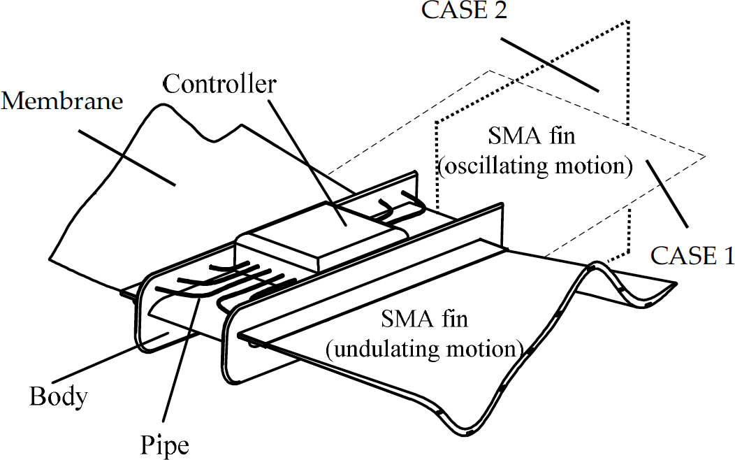
Mechanical structure of multiple SMA fins-actuated BIUV
From the perspective of practical application, two common arrangement styles of multiple fins on the BIUV are considered: firstly, the posterior fin (oscillating motion) that is set parallel to the anterior fins (undulating motion), defined as Case 1; secondly, the posterior fin that is set perpendicular to the anterior fins, defined as Case 2. A preliminary experiment is conducted to compare the force generated by the BIUVs equipped with the two common arrangement styles of multiple fins. The experiment system is detailed in Ref. [29]. Some results are abstracted and shown in Fig. 3.
The average force generated by the BIUV with the posterior fin perpendicular or parallel to the anterior fins at the same kinematic parameters is depicted in Fig. 3. Average force is calculated by adding the data and dividing the sum by the total number of forces during one motion period. To reduce random error, the experiment is repeated six times. The average force of Case 1 is approximately 2.4 N; in Case 2, it is 2.1 N.

Average force generated by the BIUV with the posterior fin perpendicular or parallel to the anterior fins at the same kinematic parameters (frequency 0.8 Hz, amplitude 2.5 cm, wave number 1.25. Wave number refers to the number of complete wave cycles on the fin surface).
However, the differences in propulsion force should be illustrated, and the reasons for these differences explained. Consequently, an unsteady 3D CFD method using an unstructured, grid-based, and unsteady Navier-Stokes solver with automatic adaptive re-meshing to compute the unsteady flow is adopted to study the arrangement problem of multiple fins on BIUV and the hydrodynamic interaction between the fins.
Kinematics Modelling
Definition of Coordinate System
The definitions of the parameters and coordinate system are shown in Fig. 4. The coordinate system is located in the middle of the leading edge of the posterior oscillating fin with the x-axis along the width of the fin, the z-axis along the length of the fin, and the y-axis perpendicular to the fin surface. The body of the BIUV is removed to simplify the structure. Meanwhile, a flexible thin plate with a smaller dimension is employed as a computational model.

Definition of parameters and coordinate system
All the values of the parameters to be investigated are listed in Table 1.
As mentioned earlier, the anterior paired-fin kinematics was determined as a travelling sinusoid. The posterior fin is strictly defined to be oscillating around its leading edge.
Values of parameters to be investigated

Values of parameters to be investigated
Note: the surface area of the posterior fin (L2 × W2) is fixed to 2.4 × 103 cm2. Symbols are graphically marked in Fig. 4.
Therefore, the 3D undulating motion of the fin can be expressed as

where ω is the angular frequency, k is the wave number, A is the wave amplitude, and C is constant. If the posterior fin is assumed to oscillate under the sinusoidal waveform, the angular position of the oscillating fin at time t (θ(t)) is given by Eq. (2):

where θmax is the oscillating amplitude, T is the oscillating cycle, and θ0 is the initial phase. The oscillating angular velocity (ω(t)) of the fin is obtained through the first derivation of Eq. (2):

As indicated in Eqs. (2) and (3), the maximum oscillating angle θ is determined by θmax, whereas the oscillating angular velocity ω of the fin is determined by θmax and T. The values of the parameters for fin motion are listed in Tables 2 and 3.
Values of the kinematic parameters for the anterior paired fins

Values of the kinematic parameters for the posterior fin

The 3D flow around the model is simulated using an immersed boundary method based on a discrete stream function formulation developed by Wang and Zhang [34]. The incompressible Navier-Stokes equations with additional body forces and the continuity equation are used for the governing equations:

where u is the non-dimensional velocity, p is the non-dimensional pressure, and F is the non-dimensional body forces representing the effects of the boundaries. The details of the flow solver have already been discussed extensively in connection with successfully validated solutions for numerous 2D and 3D, laminar and turbulent, steady and unsteady flow problems [34–36].
The computational domain ranges from −4.0 to 3.0 (normalized by the undulating fin length) along the longitudinal (or stream-wise) direction (i.e., the x-direction), −1.5 to 1.5 along the transverse direction (i.e., the z-direction), and −1.0 to 1.0 along the vertical direction (i.e., the y-direction). Fluid density and viscosity are constant, and the flow velocity is U. The leading edge of the anterior oscillating fin is fixed. Note that the dimensionless parameter Re is set to be 500 throughout the study, which is close to the value that BIUV can generate. The parameters are listed in Table 4.
Values of the computational domain

Values of the computational domain
*All the values are normalized by being divided by the undulating fin length
The entire computational domain is large enough to eliminate wall effect. The Re is lower than that of a real bionic object (usually 104−108). Nevertheless, in practical application, the results may provide new insights into the mechanism of the interaction of the motion of multiple fins in a vortex wake.

Mesh scheme
To accurately calculate the forces acting on the fin surface and reduce the number of meshes, a boundary schema with a growing rate ratio of 1:1.2 is applied for meshing the hydrodynamic boundary of the objects [37]. For the fluid domain, the total number of triangular cells is 1,023,336. Fig. 5 shows the mesh distribution in the fluid region and a close view around the objects.
The governing equations are discretized using the finite volume method with an implicit segregated solver approach. The Navier-Stokes momentum equations are discretized with a second-order upwind scheme, whereas pressure is interpolated using an accurate second-order scheme. An implicit first-order scheme is used for temporal discretization, with a time-step size of 0.01 s. Simulations are carried out 1000 times to simulate swimming for at least 10 motion periods. Pressure velocity coupling of the continuity equation is achieved using the SIMPLE algorithm, which is valid for the small time steps used in the simulation [37].
Convergence
For each time-step residual of the continuity equation, x-velocity, y-velocity, and z-velocity all typically converged in less than 50 iterations to a scaled residual of 0.001. Several time steps were examined more closely, indicating that solution convergence was being achieved. Grid convergence was tested using the Richardson extrapolation method described by Celik and Karatekin [38]. Several parameters describing the vortices in the wake were tested, showing that grid convergence for the fine mesh was achieved within 0.8% of the extrapolated exact values.
Unstructured Mesh Generation and Adaptive Re-meshing
In the majority of the computational domain, a new mesh distribution will be required because the positions of relevant flow features change. One approach to solving this problem is adding a moving grid system [39]. Accordingly, the grids were made to fit the deforming boundaries at each physical time step, and grid density was sufficient to resolve viscous and unsteady flows around the body surface and in the wake. As the elements (or edges) move, their geometric parameters (shape-function derivatives, etc.) need to be recomputed at each time step. If the whole mesh is assumed to be in motion, these geometric parameters need to be recomputed globally. To reduce the number of global remeshings and computation load, only a few elements surrounding the bodies are actually moved. The remainder of the field is treated in the usual Eulerian frame of reference, avoiding recomputing geometric parameters. The details of the algorithm can be found in the work of Ramamurtil et al. [40]. The boundary condition for the inlet was velocity inlet; the downstream boundary was modelled as a constant pressure outlet; the sides were modelled as no-slip walls; and the fin surfaces were simulated as a smooth no-slip wall (see [5]).

A user-defined function (UDF) is used to define the movement of the undulating and oscillating motions. The undulating motions of the anterior fins and the oscillating motion of the posterior fin are complex. Thus, the DEFINE macros DEFINE_CG_MOTION and DEFINE_GRID_MOTION were selected to describe the movement of the two objects.
Wakes were analysed only when the kinematics remained steady. Vorticity vector (ω) is a measure of the rotation of the flow field, and it is equal to the curl of the velocity vector; for a 3D flow, it is expressed as Eq. (6) (modified from Refs. [41–42]):
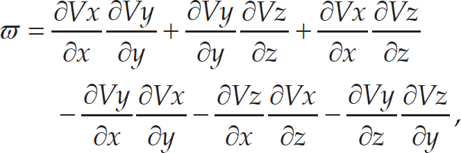
V x , V y , and V z are the particle velocity components in the x, y, z directions, respectively. ω has the unit s−1. Positive vorticity represents the rotation in the counter-clockwise direction, whereas negative vorticity represents rotation in the clockwise direction.
The force applied on the BIUV is caused by fluid friction and pressure. Friction force (Ff) arises as a result of the viscosity of water in areas of flow with large-velocity gradients. Friction force depends on the wetted area and swimming speed, as well as the nature of the boundary layer flow. Pressure force (Fp) is formed by two components: pressures formed in pushing water aside for the fin to pass (form drag), and energy lost in the vortices formed by the fin motion as it generates lift or thrust (vortex or induced drag). These forces are expressed respectively as follows:


where p and τ are normal stress and shearing stress, respectively, α is angle to x axes, and A is the effective area of BIUV that in contact with the fluid. Hence, the total force is given by

Here, two important force components are considered: the force parallel to the x axis (Fig. 4), defined as drag force, and the force parallel to the y axis (Fig. 4), defined as lift force. These two forces are non-dimensionalized as drag coefficient CD and lift coefficient CL, defined below:

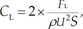
where FD and FL are the total forces produced by the BIUV in parallel to the x and y axes, respectively, ρ is the fluid density, U is the relative propulsion velocity, and S is the upstream surface area.
In this section, some numerical results of the present topic will be presented. A comparative analysis between the two cases (parallel fins [Case 1] and perpendicular fins [Case 2]) is performed. Pressure contours, streamline of the flow field, vortex in the wake, etc., are shown to thoroughly illustrate the differences.
Pressure Distribution
Pressure distribution on fins was computed and integrated to provide fin forces that were decomposed into drag force (Eq. [10]) and lift force (Eq. [11]). Two slices are extracted from the computational area; the pressure contours are illustrated at d1 = 0 cm, d2 = 10 cm, L2=60 cm, f=4 Hz, A=4 cm, and λ=1.25, as shown in Fig. 6. Both the anterior undulating fins and posterior oscillating fin move at frequency=4 Hz. Fig. 6 (a) shows the parallel case, and Fig. 6 (b) the perpendicular case.
The negative- and positive-pressure regions are significantly developed through the motion of fins, and these gradually travel downstream on both sides. The force is attributed to the pressure, and it is closely related to the pressure distributions over both sides of the fins. The pressure contours of the flow field (Fig. 6) reveal that positive-pressure regions are more intense than negative-pressure regions in both cases. However, the pressure distribution is different in the two cases. The pressure difference between the upper and lower surfaces pulls the fin, thus generating force. Followed by the decrease or increase of the force as the pressure difference declines or ascends, minimum propulsion force occurs when the pressure difference is very small during fin motion.
Iso-surfaces of Vorticity
Fig. 7 shows the non-dimensional snapshot of the iso-surface fields of the vorticity. The anterior fins have a certain effect on the posterior fin in the vortex formation. The vorticity shed behind the undulating fin is carried downstream by the superposed uniform flow. The posterior fin situated between the vortex streets trailing two anterior fins experiences an ambient flow, assisting forward propulsion. Energy can be harvested by the posterior fin from the wake of the anterior fins. The wake of the harvesting fin contains less lost energy than that of a lone fin. Properly timed oscillations entrain incoming ortices for energy harvesting at the proper position relative to the anterior fins. However, these oscillations indicate that an attached leading-edge vortex is visible on the posterior fin and is enhanced by incoming vorticity from the anterior fins. Water flow in the gap between the anterior fins and posterior fin is substantially affected by the vorticity from the anterior fins. Comparisons between Case 1 and Case 2, as illustrated in Figs. 7(a) and (b), reveal that the vortex shed from the trailing edge of the undulating fins in Case 1 has extensive influence on the leading edge of the posterior fin. In Case 2, this influence is limited in the region of the posterior fin.

Pressure contours (Pa) of the flow field (d1=0 cm, d2=10 cm, L2=60 cm, f=4 Hz, A=4 cm, and λ=1.25)

Iso-surfaces of vorticity at t = T. (a) Posterior fin parallel to the anterior fins (Case 1). (b) Posterior fin perpendicular to the anterior fins (Case 2) (T: period of the motion, d1=0 cm, d2=10 cm, L2=60 cm, f=4 Hz, A=4 cm, and λ=1.25).
In this section, the effect of distance between two anterior fins (d1) on propulsion-force generation of the posterior fin is illustrated. Four different distances are considered (d1 = 0, 20, 40, and 60 cm). The time-varying non-dimensional drag coefficient CD and non-dimensional lift coefficient C L with four different distances (d1), are presented in Fig. 8. Based on calculations, both non-dimensional drag coefficient CD and non-dimensional lift coefficient CL sinusoidally varied for all the cases considered. Thus, to clearly exhibit time-dependent forces, the results during two movement periods are shown in Fig. 8. The drag defined in the FLUENT simulation is the total force of the viscosity drag, pressure drag, and pressure thrust along the flow direction.
Drag can be either positive or negative. A negative drag coefficient CD indicates that pressure thrust is greater than the sum of the viscosity drag and pressure drag, and vice versa. Overall, with the increase of distance between the two anterior fins (d1), propulsion force decreases in both cases. Although the peak value of lift force increases with d1, time-averaged lift force approaches zero during the entire motion process, indicating that the fins will propel themselves straight ahead. In Fig. 8 (b), the value of time-averaged non-dimensional drag coefficient in Case 2 is greater at d1 = 20 cm compared with other values. It seems strange that non-dimensional lift coefficient CL is small at d1=0 cm compared with other distances. Future work will focus on this and attempt theoretical and experimental clarifications.
Fig. 9 shows the particle traces past fins with different distances (d1. Particles are released along a rake parallel to and just upstream of the leading edge of the anterior undulating fins. Using the instantaneous velocity field, the positions of these particles are obtained by integrating the velocity at these points until these traces exceed a specified length or the particles end on a solid boundary or exit the computational domain. As shown in Fig. 9 (a), the vortex appears around the trailing edge and reaches the maximum in the edges on both sides of the undulating fins. The width of vortexes in the wake of undulating fins is enlarged when d1 changes from 0 cm to 60 cm. At d1=0 cm, the vortexes shedding from the anterior fins concentrate around the centre of the two fins. In this condition, the posterior fin oscillates through the vortexes and redirects the oncoming flow, maximizing the energy. When d1 increased, the vortexes are more dispersive. These dispersive vortexes reduce the energy that could be harvested by the posterior fin, thus decreasing the thrust generated. Compared to Case 1, the posterior fin in Case 2 (Fig. 9) harvests less energy from the vortexes produced by the anterior fins because of the change of vortex formation. When d1 is increased, the vortexes gradually move away from the oscillating region of the posterior fin, causing the decrease of propulsion force.

Change of non-dimensional drag coefficient CD and non-dimensional lift coefficient CL with different distances (d1). (a) Posterior fin parallel to the anterior fins (Case 1). (b) Posterior fin perpendicular to the anterior fins (Case 2) (f=4 Hz, A=4 cm, and λ=1.25).
The effect of distance between anterior undulating fins and posterior oscillating fin (d2) on propulsion-force generation of the posterior fin is detailed in this subsection. Four different distances are considered (d2 = 5, 10, 30, and 50 cm). The time-varying non-dimensional drag coefficient CD and non-dimensional lift coefficient CL with four different distances (d2) are presented in Fig. 10. Both of them sinusoidally change with time. However, the time-varying lift force is almost the same among the four distances (d2). The time-averaged lift force also approaches zero during the entire motion process. Distance (d2) has a more significant effect on the propulsion force in Case 1 than in Case 2. Furthermore, the influence of anterior disturbance on the propulsion force generation of the posterior fin is reduced with the increase of distance (d2); however, propulsion force produced by the posterior fin is always larger than the case without disturbance of the anterior fins. To some extent, this finding implies that the fin takes advantage of the energy from the anterior vortices to enhance its propulsion force.

Particle traces past fins with different distances (d1). (a) Posterior fin parallel to the anterior fins (Case 1). (b) Posterior fin perpendicular to the anterior fins (Case 2).

Change of non-dimensional drag coefficient CD and non-dimensional lift coefficient CL with different distances (d2). (a) Posterior fin parallel to the anterior fins (Case 1). (b) Posterior fin perpendicular to the anterior fins (Case 2) (f=4 Hz, A=4 cm, λ=1.25).
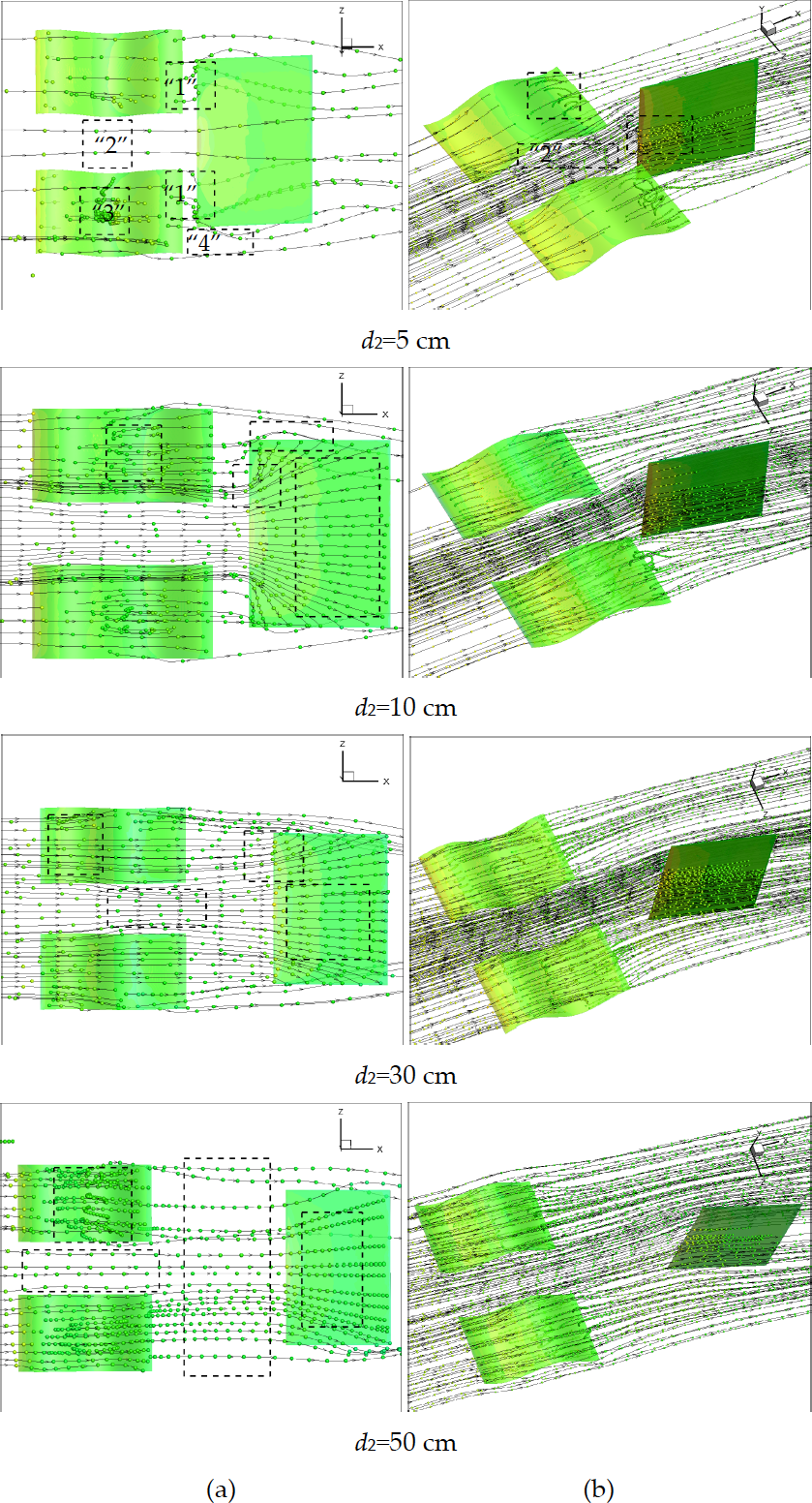
Particle traces past fins with different distances (d2). (a) Posterior fin parallel to the anterior fins (Case 1). (b) Posterior fin perpendicular to the anterior fins (Case 2).
Fig. 11 shows the 3D particle traces past fins with different distances (d2). Four important regions are marked with “1,” “2,” “3,” and “4” in Fig. 11 (a). Here, “1” indicates the interaction region between the anterior fins and posterior fin. In this region, the flow dramatically changes. It contains a vast amount of energy because of the redistribution of flow from the anterior fins, which has a direct effect on the posterior fin. When distance (d2) increases, the flow disturbance between the two fins is eased. “2” is the region between two anterior fins. In region 2, the flow is not severely affected by the motion of the anterior fins. In Fig. 12 (b) (Case 2), this region seems to have more effect on the posterior fin than in Case 1. “3” is the fin surface region. With the undulating motion of the fin in this region, the separation of the boundary layer is restrained. This phenomenon is also mentioned by Yang and Yin [43], who suggest that the separation is restrained when the C/U ratio is greater than 1. A more detailed study on the effect of C/U on the suppression of separation, drag reduction, and power consumption can be found in Ref. [44]. “4” stands for the lateral edge region of the posterior fin. Vortex rolling is detected in this region.
The effect of the length of the posterior oscillating fin (L2) on its force generation is discussed in this subsection. Fig. 12 shows the time-varying non-dimensional drag coefficient CD and non-dimensional lift coefficient CL with different lengths of the posterior oscillating fin (L2). In both cases, propulsion force varies with time. In Fig. 12, propulsion force is decreased with the increase of L2; this variation is more observable in Case 2. An offset is observed in Fig. 12. This observation is confusing. Thus, clarifications will be made in the future.

Time variation of non-dimensional drag coefficient CD and non-dimensional lift coefficient CL with different posterior oscillating fin (L2) lengths. (a) Posterior fin parallel to the anterior fins (Case 1). (b) Posterior fin perpendicular to the anterior fins (Case 2) (f=4 Hz, A=4 cm, λ=1.25).

Particle traces past fins with different lengths (L2). (a) Posterior fin parallel to the anterior fins (Case 1). (b) Posterior fin perpendicular to the anterior fins (Case 2). Fig. 13 illustrates the particle traces past fins with different lengths (L2). The change of length (L2) of the posterior oscillating fin has some effect on the flow pattern. As shown in Fig. 13 (a), the flow passing the posterior oscillating fin is moderated with the increase of L2. In Fig. 13 (b), the distance between the paired vortexes on each side of the posterior oscillating fin is shown to increase, whereas the area affected by the anterior fins is reduced.
This section further discusses some extraordinary phenomena pointed out in Section 5.
Dimension Parameters
A comparison is made to investigate the time-averaged non-dimensional CD relative to different dimension parameters, as depicted in Fig. 14. Fig. 14 (a) shows the time-averaged non-dimensional CD changing with different distances between two anterior fins (d1). Fig. 14 (b) shows CD changing with the distance between the anterior undulating fins and the posterior oscillating fin (d2). Fig. 14 (c) shows CD changing with the length of the posterior oscillating fin (L2). Time-averaged non-dimensional CD increases with d1, d2, and L2 in both cases, indicating that the propulsion force that propels the BIUV forward is decreased. One exception is observed in Fig. 14 (a), as indicated by the dotted rectangle. In this condition, CD is relatively larger, indicating that less propulsion force is generated than with adjacent parameters. The posterior fin that is parallel to the anterior fins (Case 1) always generates a larger propulsion force than the posterior fin that is perpendicular to the anterior fins (Case 2), with the same dimension parameters. Thus, Case 1 is a better choice than Case 2 for adoption in the present BIUV.
Kinematic Parameters
Case 1 is given more attention in this section because its propulsion performance is better than Case 2. The influence of kinematic parameters of the anterior fins on the posterior oscillating fin in Case 1 is discussed here. The kinematic parameters include undulating frequency (1, 4, 8, and 10 Hz), amplitude (2, 4, 6, and 8 cm), and wave number (0.5, 1.0, 1.25, and 1.5). The results are shown in Figs. 15–17.
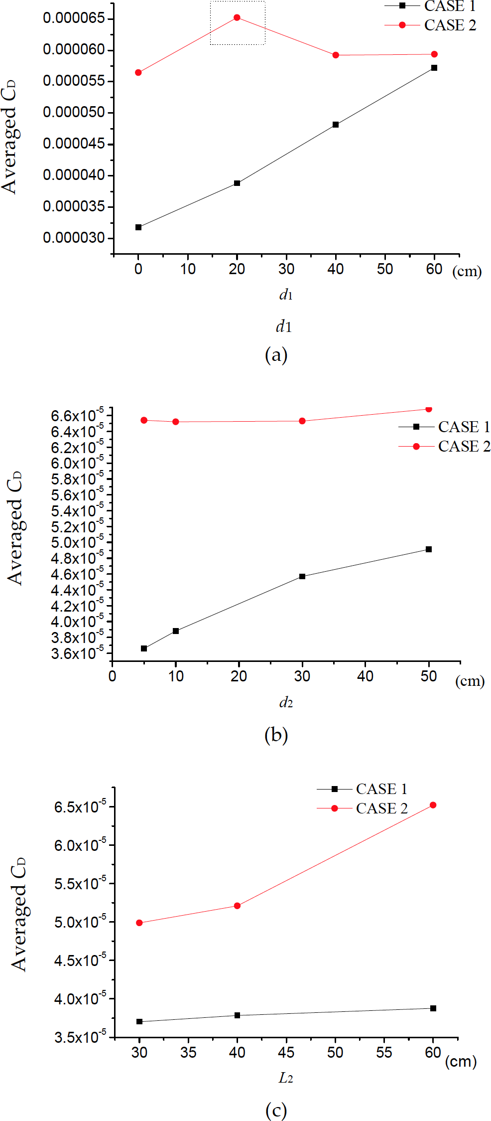
Time-averaged non-dimensional CD relative to different dimension parameters. (a) Time-averaged non-dimensional CD changing with different distances between two anterior fins (d1). (b) CD changing with the distance between the anterior undulating fins and the posterior oscillating fin (d2). (c) CD changing with the length of the posterior oscillating fin (L2).
The time variation of the non-dimensional drag coefficient CD of the posterior oscillating fin is plotted in Fig. 15 (a), and its time-averaged value is shown in Fig. 15 (b). In Fig. 15 (a), the peak value of time-varying CD varies with frequency, except for the frequency = 4 Hz, where a standard sinusoid with an equal peak value is presented. At frequency = 1 Hz, the time-averaged CD is approximately 3.6 × 10⁻⁵ and reaches the minimum value 3.2 × 10⁻⁵ at frequency = 4 Hz; time-averaged CD increased again at a higher frequency. This variation indicates that the propulsion force of the BIUV increases with a certain frequency range (4 Hz) and decreases when frequency becomes larger (> 4 Hz) in the present computational condition. This result implies that the synchronous movement (the same motion frequency) of the anterior fins and posterior fin promotes the propulsion performance of the BIUV. This implication is supported by several relevant findings. For example, Jia and Yin [45] carried out an experiment to denote passive oscillations of two tandem flexible filaments in a flowing soap film. The results showed that the downstream filament oscillates in the vortex street that is shed from the upstream filament. The downstream filament draws energy from the flow to increase its kinetic energy, particularly when these two tandem flexible filaments oscillate in the same frequency.

Influence of frequency of the anterior fins on the posterior oscillating fin in Case 1. (a) Time variation of non-dimensional drag coefficient CD. (b) Time-averaged non-dimensional drag coefficient CD. (λ=4 cm, λ=1.25).
Fig. 16 shows the influence of the amplitude of the anterior fins on the posterior oscillating fin in Case 1. Fig. 16 (a) illustrates the time variation of the non-dimensional drag coefficient CD, and Fig. 16 (b) indicates the time-averaged value. With the increase of the undulating amplitude of the anterior fins, time-averaged CD decreases, which means that the propulsion force generated by the posterior oscillating fin increased. Unlike in Fig. 15 (a), the peak value of the time-varying CD is constant.

Influence of amplitude of the anterior fins on the posterior oscillating fin in Case 1. (a) Time variation of non-dimensional drag coefficient CD. (b) Time-averaged non-dimensional drag coefficient CD.(f=4 Hz, λ=1.25).
The influence of the third kinematic parameter (wave number) is considered, and the results of time-varying and time-averaged CD in Case 1 are shown in Fig. 17. Wave number is defined as the ratio of fin length and wavelength. Generally, the time-averaged CD decreases with the increase of the wave number of anterior fins. However, a further increase in wave number (> 1.25) will reduce the propulsion force of the posterior oscillating fin. Similarly, the peak value of time-varying CD is also constant at different wave numbers.

Influence of wave number of the anterior fins on the posterior oscillating fin in Case 1. (a) Time variation of non-dimensional drag coefficient CD. (b) Time-averaged non-dimensional drag coefficient CD. (f=4 Hz, A=4 cm).
In this paper, a BIUV is built using multiple lightweight bio-inspired SMA fins. Using an unsteady 3D CFD method combined with a UDF program, two typical arrangements of multiple fins on the BIUV are compared, and the hydrodynamic interaction between the fins is investigated. The kinematic parameter effect of anterior fins on the non-dimensional drag of the posterior fin in Case 1 is also implemented. In summary, the researchers conclude the following:
The distribution formation of multiple fins on the BIUV does contribute to the different performance of the newly developed BIUV. The posterior fin that is parallel to the anterior fins (Case 1) can be seen to generate a larger propulsion force than the posterior fin that is perpendicular to the anterior fins (Case 2), with the same dimensions and kinematic parameters. Thus, Case 1 is superior to Case 2.
The force generation of the posterior oscillating fin is reduced with the increase of distance (d2). However, this force is always greater than in the case without disturbance of anterior undulating fins. This result implies that the fin can gain extra energy from the upstream vortexes to optimize its performance, and a small distance (d2) is appreciated.
With the increase of distance between the two anterior fins (d1), as well as oscillating fin length (L2), the propulsion force of the posterior oscillating fin decreases. Hence, to produce a larger propulsion force, d1 must be narrowed and L2 must be shortened.
The synchronous movement (the same motion frequency) of the anterior fins and posterior fin may propel the BIUV.
The generated propulsion force of the oscillating fin also increases with amplitude and wave number of the anterior undulating fins. However, this force decreases with wave number when it exceeds 1.25 in the current CFD study.
Our future work will focus on the following four aspects. First, a further investigation should be undertaken to explain why non-dimensional lift coefficient CL is small at d1=0 mm compared with other distances. Second, an experiment should be carried out to verify the simulation results. Third, the effect of other parameters, such as vertical position, on the performance of the BIUV should be investigated. The change of the posterior oscillating motion of the fin will also be considered in the future.
Footnotes
8.
The authors gratefully acknowledge the financial support of the Taizhou Vocational and Technical College through grant #2013YB01. We also thank Prof. Zhang Shiwu and Dr Jia Laibing from the University of Science and Technology of China (USTC), Dr Wang Shizhao from the Chinese Academy of Sciences, and Dr Cai Yueri from Beihang University for their valuable suggestions and comments.