
Abstract
In the past decade, biomimetic undulating fin propulsion has been one of the main topics considered by scientists and researchers in the field of robotic fish. This technology is inspired by the biological wave-like propulsion of ribbon-finned fish. The swimming modes have aquatic application potentials with greater manoeuvrability, less detectable noise or wake and better efficiency at low speeds. The present work concentrates on the evaluation of fin-ray trajectory tracking of biorobotic undulating fins at the levels of kinematics and hydrodynamics by using an experimental-numerical approach. Firstly, fin-ray tracking inconsistence between the desired and actual undulating trajectories is embodied with experimental data of the fin prototype. Next, the dynamics' nonlinearity is numerically and analytically unveiled by using the computational fluid dynamics (CFD) method, from the viewpoint of vortex shedding and the hydro-effect. The evaluation of fin-ray tracking performance creates a good basis for control design to improve the fin-ray undulation of prototypes.
Keywords
1. Introduction
Biological systems have achieved and preserved their remarkable and energetic adaptability to the environment through millions of years' natural selection and evolution [1],[2]. In particular, as the typical underwater evolutionary representative, fish have surely inspired endless imaginations and inspirations in mankind with their superb swimming, dexterous performance, spacious locomotion and excellent compatibility within flow environments [3]. Robotic fish is one type of underwater robot that has been inspired by live fish locomotion. The bio-inspired device aims at improving the performances of underwater vehicles by using new propulsion modes.
The marine environment has a profound relationship with our ecosystem, economy and daily lives, since there are rich and various resources in oceans all over the world. Under such circumstances, underwater vehicles are concerned and endowed with many missions, such as harvesting resources ranging from food to oil, monitoring our environment, studying abyssal species, supporting national sovereignty defence and transporting goods and materials in adverse situations. These newly emerged necessities care more about manoeuvrability within a compact space, efficiency at low speeds and compatibility with environments in addition to steady cruising performance. However, traditional propulsion, e.g., axial propellers, cannot satisfy these requirements.
In terms of biomimetics, it is important for mankind to learn and mimic the aforementioned distinguished abilities from natural biology to effectively promote the development of science and technology [1,4]. Many biologically inspired robots have been proposed and developed during the past few years. As a typical case, biomimetic undulating fins (see, for example, [5]-[12]) have gained valuable inspiration in terms of higher efficiency, greater manoeuvring or stabilization and better state-keeping at low speeds from the fish, which generally swim using undulations of their long-based ribbon fins. Typical undulating fin prototypes are shown in Fig. 1.
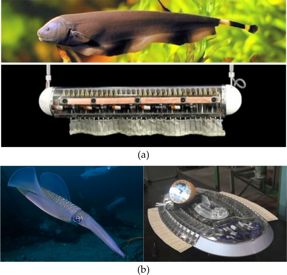
Selected robotic undulating fin prototypes: (a) a knifefish (black ghost) inspired robot with single bottom undulating fin, which was developed by MacIver et al. at Northwestern University, USA, adapted from [6]; (b) a squid inspired underwater robot with two undulating side fins, developed by Toda et al. at Osaka University of Japan, adapted from [12].
Several approaches have been employed to investigate biomimetic undulations. These include analytical models [13], [14] and more recently numerical simulations [6], [15]-[17], and prototype design and experiments [5]-[10], [12], [15], [18]-[20]. These undulating fins were expected to effectively complement conventional underwater propellers in the above-mentioned performance aspects. Nevertheless, performance of the existing fin prototypes is hardly satisfactory in terms of efficiency, stabilization or manoeuvrability. Thus, the expected resource exploration of the marine environment currently remains a far-off situation.
As a result, scientists and engineers have concentrated efforts on how to improve the performance of robotic undulating fins. For instance, smart materials [8][21]-[23] have been utilized to replace rigid plates or foils driven by motors and are expected to enable compact design and energy consumption by using direct flexible actuators. Different from designing novel mechanisms (for example, smart materials), this paper penetrates fin-ray hysteresis of biorobotic undulating fins via an experimental-numerical approach.
For a detailed study, hysteresis nonlinearity will be presented experimentally in the form of hysteresis loops between the desired and actual undulating waveforms. Furthermore, this nonlinear feature is analytically unveiled by using the computational fluid dynamics (CFD) method, from the view of vortex shedding and flow evolving during undulations. Since hysteresis is an inherent property of smart materials, the proposed method should be useful and applicable for newly developed smart material-driven robotic fish [8][10].
2. Biorobotic undulating fin
Through millions of years of evolution, biological wave-like undulation has developed the ability to maintain the necessary manoeuvrability it needs, even within compact and complicated spaces [2]. Moreover, the undulation mode produces fewer disturbances during run and hence, exists in harmony with the surrounding environment.
2.1. Prototype of biorobotic undulating fins
As relevant to the specified requirements in oceanic exploration, a series of robotic fin prototypes have been designed to mimic evolutionary wave-like locomotion [5]-[12].
As shown in Fig. 2, the underwater robot (RoboRay [2] [15][19]) with two undulating fins have been proposed and developed for potential application of oceanic species exploration. The undulating fins (RoboGnilos), as the main propeller of RoboRay, are symmetrically distributed on each side. It is time consuming to construct kinematics, forces and flows created by biomimetic undulations, because there is inevitably coupled action between the two undulating fins and other components in RoboRay. Therefore, an independent undulating fin (RoboGnilos [7]) was constructed as a well-functioning and validated biorobotic model, allowing for a controlled investigation of hydrodynamic behaviours throughout a parameter space that may be difficult to reach with the entire underwater robot.

RoboGnilos, the biorobotic undulating fin inspired by natural undulating-finned fish and RoboRay, the underwater robot with two side undulating fins.
The biomimetic undulating fin, RoboGnilos, consists of nine fin rays, one whole membrane, one base, nine undulatory drivers and one undulation controller [7], as shown in Fig. 2. Wave-like propulsive undulation is generated by controllable inerratic lateral oscillation of each fin ray. Under this architecture, we can set various undulatory parameters into the controller to produce forward or backward propulsive undulations; correspondingly, the fin can achieve opposite thrust against the undulatory waveforms' transferring direction.
2.2. Equation of fin-ray undulation
In terms of prior works in [2], [7], [15] and [19], propulsion velocity and efficiency are indeed related to the undulatory waveforms generated by the fin controller. With regard to RoboGnilos, propagating waves are actively driven by fin rays and transfer along the flexible passive membrane. Accordingly, motion of fin rays is emphasized for kinematics modelling and computational hydrodynamics. Essential parameters of fin-ray locomotion include the undulation amplitude, the undulation frequency, the fin-ray initial phase and the undulation wavelength. According to the previously proposed undulation kinematics model [7], the ith fin ray's desired oscillation angle è d,i (t) (i = 1, 2,…, n) is defined as:

where ë is the undulation wavelength, ÄL is the distance between two neighboured fin rays, f u is the undulatory frequency, ö0,i is the initial phase, è m,i is the oscillatory amplitude and n is the number of fin rays.
The phase difference between neighboured fin rays plays a critical role in wave propagation. Biomimetic undulation enables the robotic fin to change the motion direction from forward to backward (or vice versa) by reversing the phase difference between neighboured fin rays. If the phase difference of two neighboured fin rays is defined as ÄP (unit: rad), we have

Substituting (2) into (1), we obtain
in which T u is the undulation cycle, which is equal to 1/f u .
By virtue of the proposed kinematics model, the control for desired propulsive waveforms can be transformed into several tasks of tracking the desired fin-ray oscillatory angles,

As for this developed kinematics model, each parameter has its obvious physical meaning in mechanical systems; therefore, it should be of importance for the biorobotic fin to discover the optimal parameters from natural fish by using biological observation and analytical methods. Furthermore, the undulation controller should be capable of tracking the waveforms determined by these bio-inspired parameters, which can generate good performance in biology.
3. Kinematics hysteresis of fin-ray undulation
The developed prototypes provided an essential basis for the investigative propulsion performance of the biorobotic undulating fin. Results showed that its achieved performance is still far from the initial expectation of dexterous manoeuvring and other sought functions, despite the prototype being able to imitate fish swimming modes. Consequently, it is necessary to unveil the bottleneck in this field and to inspire effective solutions.
3.1. Testing of Fin-ray undulation
Biomimetics workflow in wave-like undulation can be summarized as follows. Optimal propulsive waveforms are learned from the biological observation of fish swimming; these waveforms can then be equally transformed into controllable parameters in the fin-ray kinematics model. The learned and designed parameter trajectories are imported into each fin ray. The actuation controller should be responsible for driving the hardware fin rays to track the desired trajectories.
In fin-ray tracking performance experiments, RoboGnilos was used as the testing platform. The water tank and supporting environment were kept the same in [7], [18] and [19]. The biorobotic fin was tested in a water tank with the dimensions 5.00 m long, 2.50 m wide and 1.25 m deep. In order to extinguish the water environment influence, the tank water was kept still prior to each testing trial. Moreover, the fish tank, the bracket frame and the raster ruler were fastened and retained to decrease circumfluence and vibrational disturbance.
Fin-ray trajectory tracking performance was evaluated with some specified undulation parameters via an experimental approach. Both of the desired and measured values on the fin-ray undulating angles were recorded simultaneously for further consideration of the fin ray's tracking performance. Typically, the related parameters were set as f u = 2Hz, θ m,i = 15°, ö0,i = 0 in the testing experiments.
3.2. Kinematics hysteresis
Under the desired trajectories, all the nine fin rays were imported with specified kinematics parameters. To ensure comparable analysis, the measured undulating angle data was filtered to reduce measurement noise. Meanwhile, the desired, measured and filtered undulation angles were displayed simultaneously, as shown in Fig. 3.

Fin-ray tracking inconsistency of biomimetic undulations under specified kinematics parameters. ‘A’ denotes the starting point and ‘B’ is the final point.
Obviously, the measured output angle cannot keep the same phase with the desired angles. It was ensured that fin-ray tracking inconsistency was validated with remarkable loops on the desire-and-measure plane, as shown in Fig. 3. In this paper, ‘fin-ray hysteresis’ is defined as terminology for depicting the fin-ray tracking inconsistencies between the desired and actual trajectories.
This inconsistency phenomenon shows that the actual undulatory waveforms are obviously different from the desired trajectories. From the control point of view, the desired undulation angle trajectory was pre-designed and imported, but its tracking performance was not considered during further runs. The following questions consequently arise: (i) How are the hysteresis loops formed in biomimetic undulations? (ii) What are the dominant factors that cause this nonlinearity? (iii) What about dynamics effects caused by inconsistent tracking?
4. Hydrodynamic hysteresis of fin-ray undulation
With regard to the above-mentioned questions, we would like to unveil the inner mechanism of fin-ray tracking inconsistency from the viewpoint of hydrodynamics and vortex shedding by using the computational fluid dynamics (CFD) method.
Hysteresis loops display the explicit nonlinearity on the level of kinematics between the desired and actual undulating trajectories of each fin ray, as shown in Fig. 3. It is of great importance to analyse the essence of hysteresis on the level of dynamics, because the control scheme design has a direct relationship with dynamics rather than kinematics. Given the difficulty in theoretical modelling regarding complicated fin-induced hydrodynamics, computational methods are adopted into unveiling the mysteries of robotic fish swimming or robotic fish propulsion.
4.1. CFD and specifications
The evolutionary flow fields around the undulating fin were numerically analysed to gain intuitive insights for investigating the nonlinearity as shown in Fig. 3. Table I shows the specified parameters for the numerical analysis of hydrodynamics of the biomimetic undulating fin.
Specifications for CFD on fin-ray hysteresis.

The computational fluid domain was set as a circular column with a length of 5.6 m and a diameter of 1.0 m, as shown in Fig. 4. The finite volume method (FVM) was applied for mesh generating and unsteady flow solving. The time step was 0.02s. The inlet velocity was equal to 0.5m/s in this computational case, while the inlet direction was set as identical with undulation wave travelling.

Computational fluid domain and boundary conditions for CFD of biomimetic undulations.
4.2. Hysteresis in undulation thrust
The flow information, in terms of pressure, velocity and vortex distribution was recorded for each time step. According to [5], the self-propulsion thrust F T (t) and locomotive drag F D (t) can be post-processed as:


where ∂v/∂ä is the normal velocity gradient in the boundary layer (or fluid layer in the immediate vicinity of the film or body surface where the effects of fluid viscosity are considered in detail) evaluated at the surface; ä = 0;
According to undulation principles, propulsive waves are propagating from head to tail along the flexible membrane. Here, the first and last fin rays play a critical role in propulsion, because of their boundary effects in fluid mechanics. Therefore, the undulating trajectory of the first fin ray èd,1 is concerned with the caused hydro thrust F T ; the hydro thrust coefficient C T is defined as

in which A denotes the wet area of the cross section during undulations. As shown in Fig. 5, there are typical hysteresis loops in the plane of èd,1 and C T . The butterfly-like loops were analysed at length in [24] and [25].

Butterfly-like hysteresis loops between the hydrodynamic force and the fin-ray undulating trajectory of the first driving fin ray.
The hysteresis loops depicted in Fig. 3 reflect a nonlinear phenomenon in the form of kinematics, while the butterfly-like loops in Fig. 5 embody complex hysteresis at the level of dynamics. To some extent, kinematics hysteresis is comprehensively caused by hydro- and other dynamics hysteresis. For instance, elastic force provided by the flexible membrane during fin-ray motion is also categorized under dynamics hysteresis. According to control indexes, the undulation controller should compensate dynamics hysteresis in order to accurately achieve tracking in kinematics. It is useful for the next control scheme design to have a clear understanding of the butterfly-like hysteresis present in the hydro-dynamics and vortex shedding.
Since hysteresis has a close relationship with phase transition [25], [26], the phase lagging phenomenon will be emphasized in the following analysis. As mentioned above, the first fin ray is the original propagation source, as well as the direct driving factor of hydrodynamics in CFD cases. The first fin-ray time-dependent undulation angle during [8T u , 10T u ] after the flow field was stable, as shown in Fig. 6. At the same time, the surge force (namely hydro thrust) acting on the fin is also shown in the figure.

Trajectory of the first fin-ray undulation angle and the corresponding surge force during the time cycles [8T u , 10T u ] selected from the CFD cycles, adapted from [2].
The periodicity and undulation of biorobotic fins' motion has led to similarly periodic specialties of surge force. Moreover, the differences between the surge force and undulating kinematics are embodied in the frequency and phase. As shown in Fig. 6, h1 and h2 were the undulating equilibrium positions of the first fin ray during one cycle, while H1 and H2 were the maximal surge forces within one undulating cycle. The fin ray attached its velocity magnitude's maximum at h1 and h2, where the hydro surge force ought to have attained its maximal value, particularly if hysteresis nonlinearity was neglected. However, the maximal surge force approximately generated at H1≈0.1T u and H2≈0.62T u , respectively, lagged behind h1 and h2. The lagging phase was nearly 0.1T u .
On the other hand, the phase-lagging effect also existed between the minimal surge force and the maximal undulating deformation. As shown in Fig. 6, the minimal surge force approximately generated at L1≈0.36T and L2≈0.88T, respectively, was 0.1T after l1 and l2 (the maximal angular deflection position) when the head edge had the minimal velocity magnitude.
4.3. Hysteresis in vortex shedding
Hysteresis can be regarded as dynamic nonlinearity caused by phase lagging in hydro forces. Furthermore, we can also unveil hysteresis for the physical mechanism from the viewpoint of vortex shedding. This form is more intuitive and easier to be understood (see Fig. 7).

Flow field and vortex shedding patterns at the time of maximal and minimal surge force generation, selected from the same undulating cycle.
There are two vortexes with reverse rotational direction shed in the wake successively in one period, which induce a reverse Karman Street in the wake of the undulating fin. The reverse Karman Street generates a high speed jet, associated with thrust generation. As each vortex is shed by individual undulating fins, it induces a water motion that is opposite to the wave travelling direction immediately behind the fin [4], [6], [16], [17].
At the maximal surge force generation moment, namely H1, H2, a vortex has been completely shed into the wake and a high speed jet is immediately generated, as shown in Fig. 7(a) andFig. 7(c). A new reverse direction vortex soon starts generating. One positive pressure region and one negative pressure region distribute symmetrically along both sides of the fin. Contrarily, at the minimal surge force generation moment, namely L1, L2, a vortex has been generated and it is still attached and nearly on the point of shedding, as shown in Fig. 7(b) and Fig. 7(d).
Three regions of positive or negative pressure are distributed alternately along both sides of the fin, as the selected flow fields show in Fig. 7. However, the positive or negative pressure region on the front and back has a smaller magnitude. At H1 and H2, the pressure magnitude has the largest value and this can lead to the largest pressure difference between both sides of the fin. In this way, the maximum surge force as an x-direction component of pressure integral along the fin surface is obtained.
5. Concluding remarks
Biologically inspired undulating fins have been considered to mimic the superb aquatic performance of natural fish with dorsal, anal, or dorsal-and-anal fins. In this paper, fin-ray tracking performance was evaluated using an experimental-numerical approach. This study has provided in-depth insight for enabling us to design effective control schemes for compensating the fin-ray hysteresis effect. Another potential application of robotic fish is to understand and reproduce the abilities of fish with robotized systems.
On the other hand, it was found that hysteresis commonly existed in other robotics systems in the motion control of servomotors. Furthermore, various smart materials have been introduced in the fields of biorobotic fins (for example, PZT and SMA [21]-[23], [29]-[31]). The effect of hysteresis nonlinearities have also been presented in these works that include smart materials. Therefore, it is hoped that the proposed evaluation method in the present work can be extended to the trajectory control of other robotics systems driven by smart materials, servomotors, etc.
Footnotes
6. Acknowledgments
This work was supported in part by the National Science Foundation of China under grant 61005077 and grant 61273347, in part by Research Fund for the Doctoral Programme of Higher Education of China under grant 20124307110002, and in part by the Foundation for the Author of Excellent Doctoral Dissertation of Hunan Province under grant YB2011B0001.