
Abstract
Humanoid soccer robots must be able to carry out their tasks in a highly dynamic environment which requires responsive omnidirectional walking. This paper explains a new omnidirectional walking engine for a humanoid soccer robot that mainly consists of a foot planner, a zero moment point (ZMP) trajectory generator, a centre of mass (CoM) calculator and an active balance feedback loop. An analytical approach is presented for generating the CoM trajectory, in which the cart-table motion of the equations is solved using the Fourier approximation of the ZMP. With this approach, we propose using a new time segmentation approach in order to parametrize the double-support phase. An active balance method is also proposed which keeps the robot's trunk upright when faced with environmental disturbances.
The walking engine is tested on both simulated and real NAO robots. Our results are encouraging given the fact that the robot performs favourably, walking quickly and in a stable manner in any direction in comparison with the best RoboCup 3D soccer simulation teams for which the same simulator is used. In addition, the proposed analytical Fourier-based approach is compared with the well-established numerical ZMP dynamics control method. Our results show that the presented analytical approach involves less time and complexity and better accuracy compared with the ZMP preview control method.
1. Introduction
In robotics, bipedal locomotion is a form of locomotion where the robot moves by means of its two legs. This movement includes any type of omnidirectional walking or running. A humanoid robot is a robot with its overall body based on the human body, allowing it to move on its two legs. Due to its having a huge controller design space as well as being an inherently nonlinear system, it is challenging to control the balance of a humanoid robots during walking. The ZMP criterion is extensively used as a stability measure in the literature [1, 2]. For a given set of walking trajectories, if the ZMP trajectory remains steady inside the area covered by the foot of the support leg or the convex hull containing the support feet, this walking motion will be physically stable and the robot will not fall. A biped walking trajectory can be derived from a predefined ZMP reference by computing a feasible CoM trajectory. The CoM trajectory can be calculated by a simple physical model approximating the bipedal robot dynamics. Kajita et al. present an approach to generate humanoid walking motion based on the preview control of the dynamics of a simplified physical model, namely a cart-table model [3].
In humanoid soccer studies, generating omnidirectional walking consisting of straight, curved, sideways and diagonal walking, and being able to change the direction of the walking motion, improves the ability of the humanoid robot to manoeuvre with more agility in a dynamic soccer field environment. Several studies on the locomotion of humanoid soccer robots have been published which are mainly based on ZMP control approaches [4, 5, 6]. However, although many of them provide a brief explanation of their walking engine, the foot planner and the ZMP controller have not been explained in detail, and most of them do not include an active balance method.
In this paper, we present an omnidirectional walking engine to develop an autonomous humanoid soccer robot. The presented walking engine mainly consists of a foot planner, a ZMP and CoM generator, and an active balance feedback loop. The foot planner generates a footprint based on the desired walking speed and direction. The ZMP generator generates the ZMP trajectory based on the position of the support foot or the polygon containing the support feet. The CoM reference trajectory is obtained through the cart-table model and using our analytical approach based on solving the Fourier approximation of the predefined ZMP trajectory. Position trajectories of the swing foot are generated through Bezier curves based on predefined footsteps. The swing foot orientation is also kept parallel to the ground to reduce the effect of the contact force. An active balance method is presented in order to keep the robot stable during walking in the face of external perturbations. Finally, leg joint angles are calculated based on swing foot positions, CoM references and the support foot position by using inverse kinematics. Our walking engine is tested and implemented on an NAO humanoid robot. It is also used as a low-level skill for our humanoid soccer robot teams which participated in the soccer simulation league of the RoboCup competition.
The remainder of the paper is organized as follows. Section 2 outlines the related work on ZMP-based walking approaches. Section 3 presents our omnidirectional walking engine approach. In Section 3.1, the foot planner algorithm, which is used for planning the next feet positions and generating the ZMP trajectory, will be explained. Section 3.2 explains our Fourier-based analytical approach for generating the feasible CoM reference trajectory from a predefined ZMP trajectory. Our approach for the active balance, in order to keep the robot stable during walking in the face of external perturbation, is described in Section 3.4. Experimental results on both simulated and real NAO robots are presented and discussed in Section 4. General conclusions and future work are discussed in the last section.
2. Related Work
Many popular approaches used for bipedal locomotion are based on the ZMP stability indicator and the cart-table model. Biped walking can be achieved by following the reference CoM position trajectory, which is calculated based on the predefined ZMP trajectory. The relation between the ZMP and the CoM can be simplified and approximated using dynamics equations of motion of simple physical systems, such as the cart-table model [7].
There is no straightforward way to compute CoM from ZMP dynamics by solving the differential equations of the cart-table model. The approaches presented previously on how to tackle this issue are organized into two major groups: numerical and analytical approaches.
In numerical approaches, Kagami et al. proposed a numerical gait generation technique by descretizing the differential equation of the relationship between the ZMP trajectory and the CoM trajectory [8]. Kajita presented an approach to find the proper CoM trajectory based on the preview control of the ZMP reference, which makes the robot able to perform an omnidirectional walking motion [3]. This ZMP preview control approach is based on optimal control theory, which is the most applicable example of the numerical approach.
Several analytical approaches have also been investigated and have become well established to date. Kurszume et al. calculated gaits based on the analytical solution of differential equations [9]. Even though the exact solution of the cart-table differential equations can be calculated theoretically, applying this solution to generate the CoM reference trajectory is not straightforward. This is because the solution consists of unbounded cosh functions and the calculated CoM trajectory is very sensitive to the time-step variation of the walking. Takanishi et al. presented a method for generating trunk motion by transforming the ZMP reference trajectories into the Fourier series [10]. Erbatur et al. investigated a similar approach to calculate the CoM trajectories in which the solution of the cart-table model differential equation is approximated based on the Fourier representation of the ZMP equation, such that it could create straight and curved walking [11, 12].
All the mentioned analytical approaches are categorized as offline methods, which can generate the CoM reference trajectory before the robot actually moves. They are not able to connect the CoM trajectories of the different walking directions smoothly and in an online manner. Even the approach which is presented by Erbatur et al. [11] was not able to generate walking in any direction, although recently this approach has been improved in order to be able to generate diagonal walking [13]. Although by using offline methods a humanoid robot is able to walk in a single direction, generating walking in any direction and having the ability to change direction online is crucial for humanoid robots in playing soccer well. Omnidirectional walking improves the ability of a humanoid robot to avoid obstacles, which it is necessary to do in soccer.
Nishiwaki et al. presented an analytical approach based on a method for modifying the gait pattern online by connecting the current reference trajectories to a newly calculated trajectory [14]. This approach is able to generate omnidirectional walking with the ability to change the walking direction online. Harada et al. have improved similar techniques in which the ZMP reference trajectory of a walking motion is represented by a spline function, and an analytical solution to the differential equation was calculated [15]. Since these approaches segment the ZMP trajectories, they are called “time segmentation-based” approaches.
Park et al. have used Harada's approach and they improve it by using the Fourier series for representing the ZMP trajectory [16]. Park et al. proposed an alternative in the form of the Fourier series, which has been used by Takanishi et al.[10]. Takanishi et al. proposed an offline method without using time segmentation approaches. This method realizes the smooth connection of the trajectories by simultaneously calculating the ZMP and CoM trajectories, and it can approximate many different shapes of the ZMP trajectory because of the nature of the Fourier series. Although the general form of this approach is explained in [16], it not specifically explained as to how to parametrize different double-support periods. In this paper, a novel time segmentation design is explained to parametrize different double-support periods.
Numerical approaches do not seem to be completely suitable for generating the CoM reference trajectories used in humanoid soccer robot walking due to their inherent time complexity. It becomes difficult to calculate the gait within one sample period, especially when changing the direction of the walking motion in a real-time task. In contrast, analytical approaches do not have this issue. However, to the best of our knowledge, there is no published study comparing the performance of the ZMP preview control approach, which is the most popular numerical approach along with the analytical time segmentation-based approaches. In this paper, the results of the proposed Fourier-based approach will be compared with the most famous numerical method, ZMP preview control.
2.1 Cart-table Model
In this section, we explain the cart-table model with its assumptions and simplifications [7]. There are two assumptions in this model, the first assumption is that all the masses are concentrated on the cart and the second one is that the support leg does not have any mass. Although these assumptions seem to be far removed from the reality, modern walking robots usually have heavy trunks with electronic circuits and batteries inside. Thus, the effect of the leg's mass is relatively small. Figure 1 presents how the robot dynamics are modelled by the cart-table.

The cart-table model used on an NAO robot
Two sets of cart-tables are used to model 3D walking. One is for movements in the frontal plane while the other is used for movements in the coronal plane. Figure 2 shows the semantic view of a cart-table.

Schematic view of a cart-table model
The position of the CoM M is x and Zh defined in the coordinate system O. Gravity g and cart acceleration create a moment Tp around the centre of pressure (CoP) point Px. The equation (1) shows how to calculate Tp, which is the amount of moment or torque around P.

We know from [17] that when the robot is dynamically balanced, the ZMP and the CoP are identical; therefore, the moment at the CoP point must be zero, Tp = 0. By assuming the left-hand side of equation (1) to be zero, equation (2) provides the position of the ZMP. In order to generate proper walking, the CoM must also move in the coronal plane; hence, another cart-table must be used in the y direction. Using the same assumption and reasoning, equation (3) can be obtained. Here, y denotes the CoM position in y.


In applying a cart-table model to a biped walking problem, first, the position of the foot during walking must be planned and defined and then the ZMP trajectory can be derived based on the constraints of the ZMP position and a support polygon. In the next step, the position of the CoM is calculated using differential equations (2) (3). Finally, the angular trajectory of each joint is found using inverse kinematics based on the planned position of the foot and the calculated CoM.
3. Omnidirectional Walking Engine
In this section, our walking engine architecture is presented to enable a humanoid soccer robot to engage in omnidirectional walking. In order to achieve functional walking, it is necessary to decompose it into several modules and address each module independently. Figure 3 shows each module and how they interact with each other. Next, a description of each module is given as well as its functionalities.

Architecture of the walking engine modules
3.1 Foot Planner
The future support feet positions of the robot are generated by the footstep planner. During the walking process, it is necessary to plan future steps on the basis of the current state of the feet and the desired walking vector velocity. In the initial state, the robot is in double-support, and the centre of ZMP region (CZMP) is located at the centre of the line that connects the feet's centres. Next, the CZMP is transferred to the area of the support foot, the robot lifts its swing foot and then moves it to the next footprint. The CZMP changes from its initial position to the new location.
Figure 4 shows how we generate the next position and orientation of the right (swing) foot based on the velocity vector (Vx, Vy, w) in the XY plane. First, the next position of CZMP is calculated by multiplying the time duration of one step by the input velocity. This determines the linear position and orientation change that can be used to determine the next position and orientation of CZMP (x, y, θ). Next, a reference point is calculated which is used to calculate the next swing foot position. The reference point has a 55 mm distance (the half-distance of two legs in an NAO robot) at 90 degrees from the support foot. From the previous reference point and the CZMP position, the next reference point can be determined, from which the next support position can be derived. In order to rotate the robot by θ degrees, the target footstep is rotated θ degrees relative to the CZMP frame.

Next step calculation of the foot/ planner for a walking vector (x, y, θ)
Two constraints are also taken into account when calculating the target foot:
Foot reachability
Self-collision of feet
“Foot reachability” considers whether or not the robot is capable of moving its foot to the calculated target footprint, while “self-collision” considers whether or not the feet may collide with each other. These constraints are considered by defining the maximum and minimum distances of the feet in the x and y axes, which should not be violated by the newly planned step and which can be shown as follows:

The minimum distances of feet in the x and y axes, A and C, are assigned to be the foot dimensions in order to prevent the collision of the feet. For instance, A and C, for the NAO robot, are assumed to be 0.10 m and 0.05 m, respectively. The maximum distances of the feet in the x and y axes, B and D, which are related to foot reachability, are determined on the basis of the leg length and the limitations of the hip joints angles. In our NAO robot experiment, B and D are assumed to be 0.30 m and 0.20 m, respectively.
3.2 CoM Reference Calculation Based on the Fourier Approach
The CoM reference trajectory is generated based on the explained cart-table model dynamics. Our analytical approach to solve the cart-table model dynamics is explained in this section. We improve the recent general Fourier-based method proposed by Park [16]. Park et al. presented a general solution to the cart-table dynamics based on Harada et al.'s time segmentation approach [15]. They improved the Harada approach by using Fourier approximation instead of spline representation.
As it is generally known, a Fourier series can effectively approximate the various types of trajectories with periodic and continuous functions [16]. Fourier series can generate smoother trajectories compared to those which are generated using spline approximation. Using Fourier approximation is also useful for analysing the ZMP trajectory of human walking in the frequency domain [11]. The Fourier-based and spline-based time segmentation approaches have already been compared by Park [16].
Park's approach is a general solution to solving the cart-table dynamics - there is no study on how to design the time segments on a ZMP trajectory in detail. We emphasize designing the time segmentation of the Fourier representation of our generated ZMP trajectories. The intuition behind this involves improving the Fourier-based approach to include the double-support period as a parameter to the ZMP representation, which in Park's work is not addressed specifically.
The ZMP trajectory of a walking motion in our time segmentation design is segmented into three parts. The segmentation design on a ZMP trajectory for two steps walking in the X axis is shown in Figure 5. The robot begins to step at t = t0 and the first phase of the double-support ends at t = t1, the single-support is designed during the time between t1 and t2. The last part is the other double-support phase, which is segmented to the time between t2 and t3.

Design of the time segmentation for the ZMP trajectory
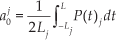
Suppose that the ZMP trajectory of each segment Pj(t) is a periodic function and has a period 2Lj, - here, Lj, = t j+1-tj -then the equation 4 shows the general form of the Fourier series representation for each segment which is given as


where N is the order of the Fourier series, j denotes each time segment (here, j = 1,2,3) and a0, ai and bi are coefficients, which can be calculated by the following equations:


The analytical solution of the position of the CoM can be obtained, by substituting Pj(t) from equation (4) into p(x) in equation (2) and solving the differential equation with respect to the CoM trajectory x(t). The solution is divided into homogeneous and particular parts, which are expressed in (6) (7), respectively. A similar solution and CoM generation technique can be applied for the ZMP dynamics in the Y axis. Since the times for beginning and ending the double-support and single-support phases are the same for the ZMP trajectories in the X and Y axes, the same time segmentation design can be used, as follows,

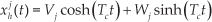

where


As can be seen in Figure 5, D0, S and D1 are the starting and ending positions of the double-support and single-support phases. Here, the order of the Fourier series N is selected as three; hence, i = 1,2,3. By choosing a higher N, usually the approximation will be more precise. In our experience, by choosing the order to be three, the approximation will have adequate precision.
By changing the segmentation parameters t0,t1,t2,t3 and t4, the presented approach can create a walking motion with varied periods of double- and single-support phases. Despite the mentioned advantages, the main challenge of using the time segmentation method is how to maintain the connectivity of the CoM trajectory between the segments. The CoM trajectory solver, equation (6), contains the unknown coefficients Vj and Wj in each segment. The unknowns values should be chosen to maintain connectivity in order to generate the complete CoM trajectory. Similarly to [15], by using equations (6) (7) and (8), the two-point boundary value problems are designed as follows:
The initial condition of the position of CoM trajectory, where D0=x1(t0) is given as:
The connection of the CoM positions of two segments, on the border of each segment in t1 and t2, where x1(t1) = x2(t1) and x2(t2) = x3(t2), are given as:


The velocities' connectivity are calculated based on the derivative of the equation (10), where:

The terminal condition of the the position of the CoM, where D1 = x3(t3), is given as:
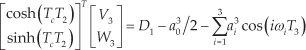
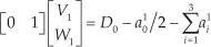
By using equation (9) to (12), six unknowns Vj,Wj,(j = 1,2,3) can be calculated as the solution of the following linear system:

where:

Under time segmentation-based approaches [16, 15], there is no formulation for considering the velocity's connectivity at the end and at the beginning of each step; as a result, the robot can become somewhat unstable at the beginning and at the end of each step. In our presented time segmentation approach, the point of changing one step to the next step is designed to be exactly in the middle of both feet. This design leads more robust step changing, since the most stable state of a walking motion is the time when the robot is in the middle of the double-support phase.
Using the Fourier approach can also improve the robustness of omnidirectional walking, since Fourier approximation can connect the ZMP trajectories of the single-support and double-support phases smoothly. In the results section, we show that the robot can walk robustly by using the presented time segmentation design. It can also change its direction and its double-support period smoothly and in a real-time manner.
3.3 Omnidirectional Walking Rotation
In the previous section, support foot positions and CoM trajectories were created. Using those trajectories, the robot can walk in any direction with a given linear velocity. The purpose of this section is to transform the orientation of both feet in order to allow for angular displacement to perform a curved walking motion or to turn in place.
The key element to control the CoM angular displacement is the control of the support foot rotation; for example, in order to rotate the CoM orientation by θ degrees, we need to rotate the support foot by θ degrees relative to the CoM orientation. To have an angular displacement controller, we need to consider three cases:
Right leg in the support phase:

Double-support phase:
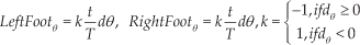
Left leg in the support phase:

Here, t is the time passed since the current step was begun, T is the current step duration and dθ is the amount of angular displacement with each walking step. LeftFootθ and RightFootgθ denote the yaw angles of the end-effectors on the both feet relative to the CoM Frame. During the double-support phase, both feet must turn in the same direction. Therefore, the variable k stands for generating different turning directions equally for both feet.
3.4 Active Balance Feedback Loop
After computing the support foot position, the 3D CoM and the swing foot trajectory, the position and orientation of both feet relative to the CoM frame should be calculated, after which it will be used in the inverse kinematics module. However, the maintenance of the balance of this generated walking motion cannot be guaranteed for two reasons. The first reason is the existence of some simplifications in the modelling of biped walking dynamics by using the cart-table model, and the other reason is the existence of the inherent noise in the leg actuators.
An active balance approach is presented in this section in order to reduce the risk of falling during walking as well as to adjust the trunk inclination as upright or with zero degrees of pitch offset. The active balance module tries to keep an upright trunk position by decreasing the variation of the trunk angles. One PD controller is designed to control the trunk angle in order to be zero. An inertial measurement unit implemented in the robot body gives the trunk inclination pitch angle. When the trunk is not upright, instead of considering a coordinate frame attached to the trunk of the biped robot, the position and the orientation of the feet are calculated with respect to a coordinate frame, which is attached to the CoM position and which maintains the Z perpendicular to the ground plane.
The PD controller calculates the rotation angle and the coordinate frame rotates with the calculated rotation angle. By using this transformation, the Z axis is maintained perpendicular to the ground plane. The foot orientation is also kept constantly parallel to ground. The transformation formulation can be obtained as follows:

The pitchAng is assumed as the angles calculated by the PD controller around the y axis. Here, FCoMFoot is a transformation matrix in which the foot is rotated based on the pitchAng. Figure 6 shows the architecture of the active balance unit, which was also on one of the modules of Figure 1.

Active balance controller diagram
In this study, the trunkpitchoffset is assumed to be zero, and the gains for P and D are assumed to be 0.5 and 0.002, respectively, which are obtained by the trail and error method. By using the presented active balance approach, the Z axis of the base coordinate is maintained perpendicular to the ground plane. Next, the foot position is calculated by using this base coordinate. Therefore, the robot tries to keep the calculated foot position on the ground or else parallel to the ground even with the inclination of trunk. The trunk inclination will be corrected and set as zero by using the presented PD controller in Figure 6. Figure 7 shows a sequence of walking by using the active balance approach while the robot's trunk inclines.

A walking scenario while the robot's trunk inclines: a) without using the active balance approach, and b) using the active balance approach
4. Results and Discussion
In this study, a simulated and a real NAO robot are used in order to test and verify the approach. The NAO model is a kid-size humanoid robot that is 58 cm high and has 21 degrees of freedom (DoF). The link dimensions of the NAO robot can be found in [20]. The simulation is carried out using the RoboCup soccer simulator. It is the official simulator released by the RoboCup community in order to simulate humanoid robot soccer matches. The simulator is based on the Open Dynamic Engine (ODE) and Simspark [21].
In order to discuss and evaluate the results from the proposed walking engine, we first analyse the results obtained by the ZMP preview controller and the presented Fourier approximation approach. The detailed explanation of the ZMP preview control approach used in this section has been described in our recent manuscript [22]. The CoM trajectory is generated based on a walking scenario, which is implemented in the simulation - the NAO robot starts to walk in the forward direction with the parameters presented in Table 1.
Parameters of the forwards walking scenario

The projection of the ZMP trajectory and the CoM trajectory onto the ground plane in the X and Y directions are shown in Figures 8.a and 8.b, respectively. They were generated by using the ZMP preview controller approach. The incremental time of the preview control loop dt is assumed to be 0.002 seconds. The value of the preview time parameter T is considered to be five seconds. Figures 8.c and 8.d show the CoM and ZMP trajectories, which are computed by using the presented Fourier approach. Here, the Fourier approach's number of terms denoted by N is assumed to be three. Based on the assumed percentage of the double-support phase and the walking period, the parameters of the time segmentation approach presented in Section 3.2 are t0 = 0, t1 = 0.08, t2=0.32 and t3=0.4.

The ZMP and CoM trajectories for forwards walking
One of the drawbacks of the Fourier-based approach in the literature is the lack of an ability to change the double-support phase during walking. In this paper, we have presented an approach to parametrize the double-support period as the input parameter of a Fourier-based walking engine. In order to test the ability of our approach, we assumed the presented walking scenario in Table 1 with varied double-support phase periods. The double-support phase period in the first two seconds of the walking motion is assumed to be 0.16 s, and in the rest of the walking motion it is considered to be 0.016 s. Figure 9 shows the CoM and the ZMP for this walking scenario. Figure 10 also shows an experiment of the implemented walking scenario in the simulation.

The ZMP and CoM trajectories when the double-support phase is changed during walking

Snapshots of the proposed forwards walking scenario in Table 1 in the simulation
As it was shown in Figure 8, the approximated and generated ZMP trajectories using the presented Fourier approach and the preview controller approach are different in terms of their shape and the accuracy of the approximation. As an example, at the beginning of the generated ZMP trajectory, by using the preview controller, the generated ZMP trajectory could not follow the reference ZMP trajectory, since the initial ZMP tracking error is considered to be zero. In order to investigate these differences, several walking scenarios are chosen in which the simulated NAO robot starts to walk in the forward direction at different speeds for four seconds. The scenarios are designed based on the walking parameters in Table 1, but the step size is considered to be 0.04 and different step periods from 0.05 s to 0.4 s with 0.05 s increments are assumed. All the walking scenarios are simulated in the same machine with the same specification. The machine used in this study is a Pentium IV 3 GHz Core 2 Duo machine with 4 GB of physical memory. The mean absolute error (MAE) of the predefined reference ZMP trajectory and the computed ZMP using both the Fourier and preview control approaches are presented in Table 2. The number of the Fourier terms denoted by N is assumed to be three. The incremental times of the preview control loop denoted by dt are assumed to be 0.01, 0.001 and 0.0001.
MAE of the computed ZMP and reference ZMP trajectories
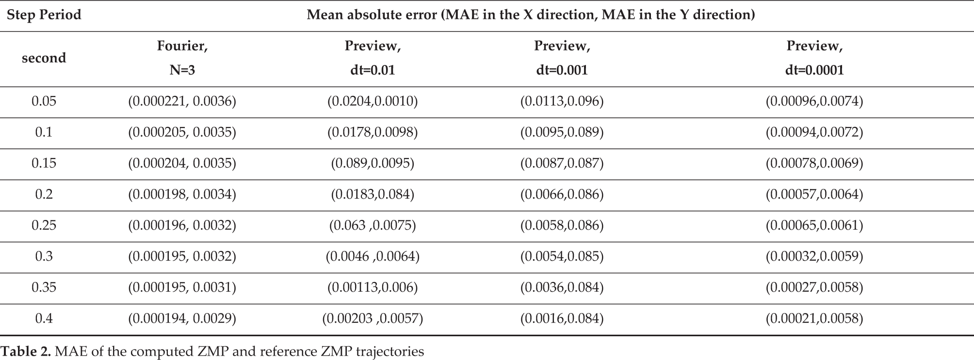
On average, the MAE in the X and Y directions achieved by the proposed Fourier method are 20- and five-times less, respectively, than those achieved with the preview control approach. Although by decreasing dt the MAE of the preview control will be decreased, achieving the performance of the Fourier approach - in practice - is not possible, since the execution time of the algorithm will be increased dramatically. The average and variation of the execution times for different specifications of the preview control and Fourier approaches are presented in Table 3.
The average (var) execution times of the methods

After executing the methods for each walking scenario on the machine, the average execution times for approximating the ZMP and for generating the CoM trajectories using the Fourier-based approach was 0.0325 seconds. It is 10-times faster than the best computation time that could be achieved using the preview control approach. For a humanoid robot that has limited computational resources, performing a real-time task such as controlling walking requires an algorithm with low time-complexity, like the Fourier-based approach.
In order to evaluate the performance of the omnidirectional walking motion generated by the proposed walking engine, the robot walks in any direction and we analyse the ability of the robot to change its direction; therefore, several walking scenarios were designed. The parameters of the walking engine used in the walking scenarios are the same as those of the previous experiments presented in Table 1; however, the robot changes its speed and direction a couple of times. In this scenario, the robot must walk forwards with a speed of 0.25 m/s for 10 seconds. Next, it must change to a sideways walking motion that lasts for 10 seconds with a speed of 0.15 cm/s. After this, it must perform a diagonal, backwards walking motion for another 10 seconds with a speed of −0.25 m/s and −0.15 m/s in the x and y directions, respectively. Finally, the robot must stop moving at the starting point. In order to show the ability of the developed behaviour to execute the scenario, the generated CoM trajectory and the footprint projected on the ground plane are shown in Figure 11.
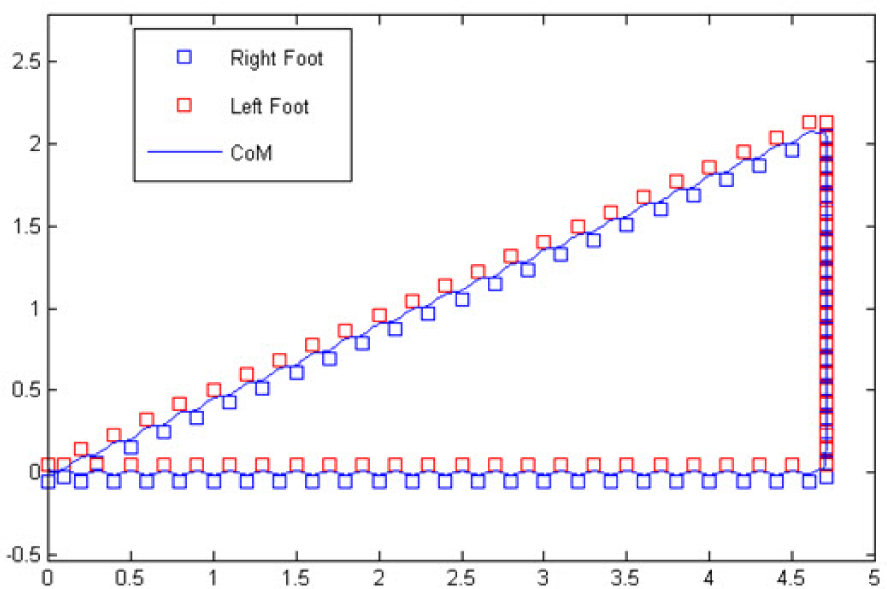
The CoM and footprint of the proposed walking scenario
For testing and evaluating the active balance algorithm, the robot performs the above omnidirectional walking scenario a speeds that are two-times higher. It performed this scenario using the active balance method four times, and then the robot performed it four more times without using active balance. The experiments showed that, in this walking scenario, without using the active balance method the robot fell three times in four tests. In particular, each fall happened when the robot changed its walking direction. In contrast, while using the presented active balance method, the robot could maintain its stability in all the tests; therefore, the stability of the robot in this scenario is improved by 75 percent using the active balance method.
The presented walking engine had already been tested and utilized as the locomotion approach of our soccer robot team FCPortugal. FCPortugal has been participating for several years in the RoboCup soccer simulation 3D league 1 , which eleven simulated NAO robots from each team playing soccer with each other. Creating a good walking engine in RoboCup soccer competitions is a critical and important task for all the participant teams. The walking engine should enable the robots to walk in a stable manner and quickly in any direction. In 2013, we changed our previous walking engine approach [23, 19] to the walking engine approach presented in this paper. Our team was able to achieve first place in the RoboCup German open competition in two consecutive years (2013 and 2014), and third place in the 2013 international RoboCup competition 2 . One of our advantages in winning those competitions was that the robots could walk quickly and change walking direction without reducing their speed, which for the other teams was a very difficult task.
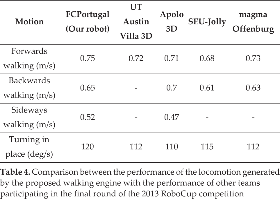
Table 4 also lists the values of some of the relevant results for the developed gait implemented on our simulated NAO compared with the corresponding behaviour from other teams participating in the 2013 RoboCup 3D soccer simulation league. By analysing the logfiles captured from the 2013 RoboCup competition 3 , the reported results are approximated based on the average speeds of the locomotion skills for teams participating in the final round of the RoboCup 2013 competition. It is also impressive that our robot can change walking direction without reducing its speed, which for other teams is a very difficult task.
Comparison between the performance of the locomotion generated by the proposed walking engine with the performance of other teams participating in the final round of the 2013 RoboCup competition
As was mentioned, the required computation time and power for executing the presented Fourier-based approach is less than the preview control approach; therefore, we used the Fourier-based approach in our implementation of the walking engine on the real NAO robot. Figure 12 shows the sequence of snapshots of the NAO robot while it performed the presented forwards walking tasks in Table 1. Here, the robot could walk at a speed of around 0.25 m/s. It is the highest speed with which we could achieving stable walking using the presented walking engine. A video of the robot performing omnidirectional walking can be found online.4

Experimental results for the NAO robot
5. Conclusions and Future Work
This paper presents an implementation of a ZMP-based omnidirectional walking engine for an NAO humanoid robot. The cart-table model is used to model the dynamics of the humanoid robot while it walks. An introduced analytical approach based on Fourier ZMP approximation is used to generate the CoM reference trajectory from the predefined ZMP trajectory. In calculating the CoM analytically, a Fourier series-based approach is used. In this paper, a new time segmentation approach is explained in order to parametrize different double-support periods. An active balance method is also proposed which keeps the robot's trunk upright in case of environmental disturbance.
The presented biped locomotion approach was tested on a simulated robot and a real NAO robot. Our results on generating the CoM reference trajectory illustrate that our presented Fourier-based approach can calculate the CoM trajectory for variable double-support phase periods using a new time segmentation-based approach. A comparison study shows that the Fourier-based approach has less time complexity and better accuracy in estimating the reference ZMP trajectories than the ZMP preview approach. By using the presented active balance method, the stability of the robot was improved 75 percent in a challenging walking scenario. By using the proposed walking engine, the robot performs well in walking quickly and in a stable manner in any direction in comparison with the best RoboCup 3D simulation teams.
The walking engine approach was used in the FCPortugal humanoid soccer robot team, and our team was able to achieve first-place in the RoboCup German Open competition, and third place in the International 3D Soccer Simulation in 2013. In the future, we plan to investigate the gait optimization problem. Since the proposed analytical method has good accuracy for any given walking parameter's value - such as the step length and size - the application of stochastic optimization would be of interest in order to optimize the values of the walking parameters with respect to different performance measures such as stability, speed and energy.
Footnotes
6. Acknowledgements
The first author was supported by foundation for science and technology (FCT) under grant SFRHIBD/6659772009. This work was funded by FCT in the context of the projects PEst-OE/EEI/UI0027/2014 and PEst-OE/EEI/UI0127/2014.
1
http://en.wikipedia.org/wiki/RoboCup_3D_Soccer_Simulation_League, ![]() 3D Soccer Simulation League (Accessed on 20/10/2014)
3D Soccer Simulation League (Accessed on 20/10/2014)
2
![]() Simulation League http://wiki.robocup.org/wiki/Soccer Simulation League (Accessed on 20/10/2014)
Simulation League http://wiki.robocup.org/wiki/Soccer Simulation League (Accessed on 20/10/2014)