
Abstract
In this study we successfully demonstrated a dexterous manipulation of sheet-like elastic objects — namely playing cards — using a high-speed multifingered robot hand system. Our goal in this research was to achieve card flicking by vibrating a fingertip of the robot hand at high speed. Firstly, we discuss card grasping in the initial state based on the geometrical conditions of the card and the kinematics of the robot hand. Secondly, we propose a strategy for performing the card flicking. In addition, we obtain the card-flicking conditions by analysing the slip between the card and the fingertip of the robot hand. In addition, we analyse an energy transition of the card based on the physical law. Thirdly, we estimate a spring constant of the card via a vibrational experiment. Then we simulate the trajectory of a flying card after the slippage, and compare a simulation result with an experimental result of the flying card's trajectory. Finally, we show the experimental results of card flicking using the high-speed robot system and the proposed method.
Introduction
Until now, various robot hands have been developed by some researchers [1–3]. We have also developed a high-speed robot hand [4]. The robot hands should achieve the following tasks:
Grasping and
Manipulation.
To do these, some functions of the robot hands are required, such as:
Dexterity,
Accuracy and
Speed.
In these functions, accuracy and speed can be achieved by our robot hand, and those of others. However, dexterity has not been achieved. The reason why is that evaluating the dexterity of the robot hands is significantly difficult. We think that dexterity can be evaluated by requiring the robot hand to carry out complex tasks. One example of such a task is that of the magic trick. Fi the case of human dexterity, magic (such as card magic and coin magic) is a special example that represents the dexterity of the human being. In particular, card magic displays the hand dexterity of humans. Therefore, we focus on the achievement of card flicking as basic manipulation in card magic. Furthermore, research on hand manipulations has not been studied. Thus, the current study represents an entirely new approach in this area. In particular, we achieve high dexterity using high-speed performance of the robot with a simple method (high-speed vibration of a finger of the robot hand). It is extremely easy to implement the proposed method with other robots using high-speed motion because of the simplicity of the method.
Some studies on humans' achievement of dexterous manipulations have been carried out; for example, juggling manipulation [5] and “kendama” manipulation [6, 7], However, these manipulations can also be executed by robot arms. The robot arms are equivalent to the upper limb of a human. Therefore, these movements are considered to be due to dexterity of the robot's arms rather than to that of its hands. Consequently, dexterous manipulation by robot hands has not been actively studied, as far as we know.
Considering target objects in robotic manipulation, rigid bodies have hitherto been handled by robots' arms and hands. However, manipulation of flexible objects has not been achieved. Flexible objects, such as rope, cable, cloth, gel and clay, exist everywhere, and manipulation of such flexible objects has recently become significantly important in the field of robotic manipulation.
For instance, Inoue and Inaba have achieved rope-knotting manipulation using visual feedback [8]. In addition, Matsuno et al. have performed the knotting manipulation of a rope using two robotic arms [9]. We have also realized one-handed, high-speed knotting of a flexible rope using a high-speed multifingered hand with tactile and visual sensory feedback [10], as well as the high-speed, dynamic folding of a cloth in the air using the same high-speed robotic system [11]. In addition, since flexible objects have infinite degrees of freedom due to their flexibility, Suzuki et al. have developed a hyper-flexible manipulator as a redundant manipulator, and have proposed its dynamics' model and control [12].
As discussed above, there has been active research on the robotic manipulation of flexible objects. In this study, we focus on a sheet-like elastic object instead of a flexible object, as discussed above. Although flexible objects cannot generate a force and motion by themselves, elastic objects have the possibility of generating new motion by converting the strain energy associated with their deformation into kinetic energy. There have been a number of studies on mechanisms for new robots that make use of the characteristics of elastic objects. Sugiyama et al. have developed a crawling and jumping robot by using the deformation of a soft material [13]. Matsuyama et al. analysed the mechanics of a jumping robot via body deformation [14], and Yamada et al. proposed a model of robotic catapults and analysed the statics based on the model [15].
Concept of card-flicking manipulation
One characteristic of an elastic object is that high-power, high-speed motion can be created by leveraging the strain energy due to the object's deformation. The previous studies mentioned above used this characteristic. In these studies, the robots were made of elastic materials and the elastic characteristics were utilized effectively in order to move the robots. To our knowledge, however, manipulations of elastic objects by a robot have not been performed actively. Therefore, we propose a manipulation strategy for handling an elastic object by using a high-speed robot system in this study. In particular, we achieved the dexterous manipulation of playing cards, as one example of elastic objects, by using the strain energy in the cards. This manipulation is a basic task of the playing cards, and this task can be considered to be valid as a first step in the cards' manipulation using the robot hand.
Summarizing the above discussions regarding the robot hand, the target object and its manipulation, this paper contributes to the following points in the field of robotic manipulation:
Highly dexterous manipulation using a robot hand,
Proposal of a simple strategy for achieving dexterous manipulation of an elastic object,
Manipulation using the characteristics of an elastic object, and
Analysis of elastic object manipulation.
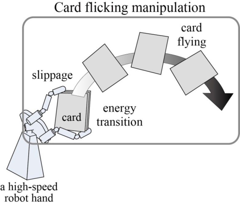
Concretely speaking, the purpose of this study was to flick a card into the air using a high-speed multifingered robot hand, as shown in Fig. 1. We propose a strategy for the card flicking. Then, we analyse the card-flicking manipulation using the proposed strategy. In particular, we discuss theoretically the slippage condition, the energy transition and the trajectory of a flying card (Fig. 1). Finally, we show our experimental results in order to confirm the validity of the proposed method. This technique of card flicking, which is called a “card spring”, is a well-known, essential technique in the field of card tricks. By achieving this technique, we expect it will be possible to carry out dexterous manipulation using high-speed motion.
The features of this manipulation include:
Use of the strain energy associated with card deformation by using a robot hand.
Use of high-speed motion in order to realize the instantaneous release of the strain energy.
Achievement of card flicking using a simple method.
In general, in order to generate a slippage phenomenon, a tactile sensor with a slip-detection function is needed. In particular, the slippage phenomenon is a very fast action, and the specified tactile sensor [16, 17] is required. However, we do not need the tactile sensor in the proposed method. This point is one of this study's original contributions. If the tactile sensor is used, it might be possible to achieve the task that we set in this research using the methods of previous work. Not use the tactile sensor is considered to be a more challenging method.
In a previous work [18], we explored a strategy, the slip phenomenon and the energy transition of card flicking. In this paper, we offer a more detailed analysis of the card flicking in addition to the abovementioned elements. Concretely speaking, we performed the identification of a spring constant of the cards, and compared the experiment's results with a simulation of card flying, as explained in Section 4.3. The results are very useful and effective for achieving elastic object manipulation with robustness, and can be expanded to the manipulation of different cards.
As far as we know, research on the card-flicking manipulation (Fig. 1) that we aim to achieve has not discussed and explored until now. Thus, we describe the previous work on manipulations of elastic objects related to our research. R. Koretake et al. developed a new mechanism for delivering cards at high speed, beyond the techniques of magicians [19]. I. G. Ramirez-Alpizar et al. performed nonprehensile dynamic manipulation of a sheet-like, viscoelastic object such as pizza dough [20]. Y. Yamakawa et al. achieved throwing and shooting manipulations of cards using a high-speed robot hand system [21]. B. S. Mahal et al. simulated deformation in elastic sheet structures using a mass-spring model [22]. Finally, W. Kraus Jr. et al. studied manipulation of flexible parts using a hybrid position/force approach [23]. As a result, this research is a new approach for the manipulation of elastic objects and is useful for improving the manipulation technique effectively.
In this section, we introduce the high-speed robot system for card manipulation. The system consists of a single high-speed multifingered robot hand and a real-time control system. Fig. 2 gives an overview of the system.

High-speed multifingered robot hand system for card flicking
This system is based on a 1 ms sensory-motor fusion system [24,25, 26] with the design concept of “dynamics matching [24]” proposed by our laboratory. The characteristics of the system are an intelligent architecture that possesses high-speed sensor feedback structure for performing high responsiveness to environmental change, and a real-time control structure for effectively achieving processes corresponding to various environmental states. We have carried out several robotic manipulations using such a system [27, 28].
Next, we explain each component of the high-speed multifingered robot hand system.
The robot hand has three fingers: a left thumb, an index finger and a right thumb. Each finger is divided into a top link and a root link. The index finger has two degrees of freedom (2-DOF), and the other digits have 3-DOF, so that the hand has a total of eight degrees of freedom in its movement. A newly developed compact harmonic drive gear ® and a high-power miniature actuator are installed in each finger link. The design of this actuator is based on the new concept that the maximum power output should be increased beyond the rated power output. The joints of the hand can be closed at a speed of 180 degrees/0.1 second. In addition, the hand has two wrist joints. The wrist part of the robot has a differential rotation mechanism, and it moves around two axes. The joint angles are set to the desired angles by PD control. The sampling rate of the robot control is 1 kHz using the real-time control system.
Robot Hand Control System
The real-time control system controls the robot hand at 1 kHz. The joint angles of the robot hand can be controlled by PD action with reference to the joint angles of the robot hand. In Fig. 2, the hand performs the card flicking.
For the real-time control system, we used a modular system produced by dSPACE Inc. [29]. In this product, a general-purpose processor and multi I/O boards can be connected using high-speed specific buses. The real-time control system consists of the processor (PowerPC-750GX (1.0 GHz)), a 16 bit and 32ch A/D board, three 5ch encoder boards and a 100Mbps Ethernet board. We developed software and a programme (implementation of a robot hand control law) using the Real-Time Workshop tool in MATLAB. The sampling rate of the system is 1 kHz (1 millisecond).

Initial state of card flicking
The size of each card is 88 mm × 63 mm, the total thickness of the 10 cards is about 4 mm and the weight of each card is about 2 g.
Card Flicking Strategy
We propose a simple strategy for achieving the card-flicking manipulation. The proposed strategy is the high-speed vibration motion of the fingertip of the high-speed multifingered robot hand. The strategy does not need feedback control using a tactile sensor, and is performed by feed-forward control only. If a tactile sensor is used, it might be possible to achieve the task using the methods of previous works. Not using the tactile sensor is more challenging, making this one of the originalities of this study.
Here we describe card grasping using the multifingered robot hand in an initial stage of the task (Section 3.1) and a finger vibration for achieving the task (Section 3.2). The detailed analysis of the card-flicking manipulation will be discussed in Section 4.
Card Grasping of the Robot Hand in an Initial Stage
Here, we consider the card grasping in the initial stage. The positions of the fingertips can be calculated by Eq. (1) based on the Denavit-Hartenberg description,

Here,
The joint angles θ>1 θ2 and θ r ) can be calculated by using the inverse kinematics in order to grasp the cards. The geometrical condition between the card and the finger is given by

where rclz [mm] and rc2z [mm] are the contact positions between the card and the upper finger in the z direction. Also, rc1x [mm] and rc2x [mm] are the contact positions between the card and the finger in the x direction. Assuming that the upper and lower fingers are located on the card corners as shown in Fig. 3(b), the contact points (rc1z, rc2z, rc1x, rc2x) can be calculated as follows:

where d is the diameter of the finger.
Given the joint angle θ1 of the upper finger, θ2 and θ r can be obtained by solving the inverse kinematics with the geometry condition (Eq. (2)).
This section explains the strategy for card flicking after the hand grasps the card. Fig. 4 shows an overview of the card flicking strategy.

Overview of the card-flicking manipulation strategy
We propose a strategy that achieves card flicking by using high-speed vibration of the finger. The flow of the card flicking can be summarized as follows:
Deform the cards by pressing them with the finger (Fig. 4(1)).
The strain energy increases due to the card deformation: E0 → E0 + ΔE, where E0 [N m] is the strain energy in the initial state, and ΔE [N m] is the increase in strain energy (Fig. 4(2)).
Release the finger pressure as soon as a slip occurs between the cards and the finger (Fig. 4(3)).
The strain energy is released, being converted into kinetic energy, thus flicking the front card: E0 + ΔE → v, where v = [v x , v y , v z ] T is a velocity vector (v x , v y , and v z [m/s] are the velocities in the x, y and z directions) (Fig. 4(4)).
Continuous card flicking can be performed by repeating these actions (1-4).
The finger vibration is performed based on the following equation:

where θ v [rad] is the reference joint angle of the top link of the upper finger for finger vibration, A [rad] is the amplitude, ω [rad/s] is the frequency and t [s] is time. In this study, A and ω are set at 0.2 [rad] and 2π×20 [rad/s], respectively.
By using the finger vibration, the card deforms and the grasped position changes due to slippage between the card and the finger. This allows card flicking to be performed. An analysis of the card flicking is described in the next section, as is analysis of the energy required for card deformation. In addition, the trajectory of a flying card after the slippage will be analysed. In the behavioural analysis of the flying card, we can also estimate a spring constant of the card based on the theory of the plate vibration.
Analysis model for slippage from the front view
The card-flicking task is divided into three phases:
slip phase (Section 4.1),
energy transition phase (Section 4.2) and
card flying phase (Section 4.3).
In this section, we analyse each phase based on their physical laws, and discuss the possibility of card flicking and trajectory of the flying card after the card flicking has succeeded.
Slip Condition between Finger and Card for Card Flicking [18]
Here, we qualitatively derive a condition for achieving card flicking.
In order to perform the card flicking, the card should fly out of the robot hand. This can be achieved using the slip between the card and the robot hand, making it necessary to discuss the slip condition.

Analysis model for slippage from the side view
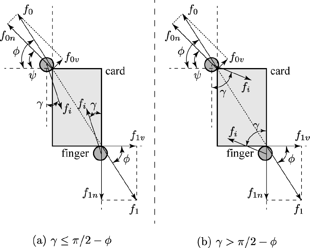
Fig. 5 shows the analysis model of the card flicking. In this situation, when the card slips on the finger, card flicking can occur. Thus, the slip condition is derived in this section, and the validity of the slip condition is discussed.
In Fig. 5, f i [N] is an input force exerted by the finger, f{0, 1} [N] are reaction forces exerted by the card and f{0, 1} are the force vectors projected onto a two-dimensional surface. f{0n, 1n} are the components of the force (f{0,1}) in the direction that connects the contact point and the finger centre and f{0v, 1v} are the components perpendicular to f{0n, 1n. ϕ (= tan−1(88/63) = 54.4 [deg]) is the angle of the card relative to the horizontal direction, ψ [rad] is the angle of the force (f0n, 1n}) relative to the horizontal direction and ³ [rad] is the angle of the input force (f i ) relative to the normal direction. Thus, we have

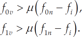
For the upper finger, the slip condition between the card and finger can be obtained as follows:

For the lower finger, the slip condition between the card and finger can be obtained as follows:

Fig. 6 shows the analysis model from the side viewpoint. In addition, we consider the slip condition shown in Fig.
6. In the initial state, α = α′ holds; however, α is not equal to α when the card deforms. Thus, we have


Analysis model for strain energy of card deformation
Taking the slip in the direction towards the fingertip into account, the slip condition of the lower finger yields
where the input force f i acts on the card in the normal direction to the tip direction.
As a result, the slip condition is qualitatively summarized as follows:
the force input f i instantaneously becomes smaller, and
In this study, we applied the first method to the card flicking in order to satisfy the slip condition. Namely, the force input f i can be made smaller by using the high-speed finger vibration. On the other hand, taking the initial state into account, it is very difficult to cause slippage using the second method.
The flicked card flies in the y direction. In order to analyse this phenomenon in this section, we discuss the energy transition from strain energy to kinetic energy. Fig. 7 illustrates an analysis model of the energy of the card. In this situation, the card model can be assumed to be approximately the spring model, because the card does not have viscous properties. Thus, the strain energy ΔE can be calculated from Fig. 7 as follows:

where Δr
j
is defined as ||

where v is the card velocity vector, m is the mass of the card and the superscript T indicates the transpose of a vector v. In addition, the card velocity can be obtained by Eq. (11).
We consider a multi-link model, consisting of a mass and spring, as the model of the card, as shown in Fig. 5. In order to simplify the analysed model, we assume that the card deformation is restricted in the vertical direction. Actually, the card deforms in an oblique direction. In addition, the card deformation is symmetrical around a centre line. The spring force is given by

Decomposing the force into y and z directions yields

Here, η
j
is the angle between
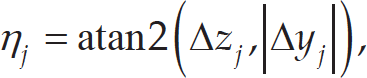
where Δy
j
= yj+1 − y
j
and Δz
j
= zj+1 − z
j
. Since the forces in the z direction are symmetrical, the forces are in opposite directions. Thus, the total force f
jz
is nearly equal to zero, namely,

where v y is the card velocity in the y direction and ε represents a small amount of other energies, such as the velocities of the card in different directions and rotation about the y direction. Consequently, the major direction of the card flicking is the y direction; that is to say, the card flies out in front of the robot hand.

Experimental condition for card vibration
Firstly, we should estimate a spring constant of a card in order to calculate the card velocity from Eq. (15), and we simulate the behaviour of a flying card. To do this, we perform a simple card vibration in order to estimate the spring constant of the card (Section 4.3.1).
Next, we simulate the card's flight based on the estimated spring constant of the card and the parabolic motion of the object (Section 4.3.2).
Identification of Spring Constant of a Card
Here we describe an estimation of a spring constant of the card using a card vibration for simulating the card's flight.
Card vibration
Experimental condition
As shown in Fig. 8, a card is fixed to the wall so it can act as a cantilever. In this situation, the force is applied to the card at its free end, and the card is bent. After that, the force is removed immediately, and then the card vibrates freely. This card vibration experiment was carried out five times.
Experimental result
The sole result of the experiments is shown in Fig. 9. This result can be captured using a high-speed camera system (Phantom v6.3) at 1,000 fps. These figures are written out every 0.01 s.
From the experimental results as shown in Fig. 9, we found that the period time of the cyclic vibration motion is about 0.06 of a second. Consequently, we found that the frequency of the free vibration was 16.67 Hz (= 1/0.06 s).
In the next section, we derive the spring constant of the card using the theory of vibration of plates [30] based on the vibration result (16.67 Hz).
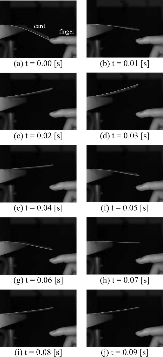
Continuous photographs of experimental result of card vibration
Here, we derive a spring constant of a card from the experimental result. In order to obtain the spring constant of the card, we analyse the vibration of the card using the theory of plate vibration [30]. We can obtain the value of the spring constant of the card theoretically in this section.
In reference [30], the flexural rigidity D of a plate (in this research, the plate performs the same function as the card in our own) can be given by

where f (= 16.67 Hz) is the frequency of the card vibration, a (= 0.088 m) is the representative length of the card and ρ(= 0.355 kg/m2) is mass density per unit area of the card. In addition, K and N are coefficients of the vibration of the boundary condition. In this situation, K and N are set at 2.56 and 1.0, respectively [30].
Furthermore, Young's modulus of the card can be obtained from the flexural rigidity D as follows,

where h (= 0.4 × 10⁻³ m) is the thickness of the card and v (= 0.3) is the Poisson ratio.
Finally, the spring constant k can be obtained from Young's modulus E, an area A (= 0.088 × 0.004 m2) of the card and a representative length L (= a) of the card as the following,

As a result, the value of the spring constant k of the card can be calculated as k = 61.5 [N/mm]. From the serial connection of the springs as shown in Fig. 7, a whole spring constant K of the card can be obtained using,

Therefore, since the value of the spring constant of the card is very small, the estimated spring constant k can be considered to be valid.
Based on the estimated spring constant k derived from Eq. (18), we calculate a card velocity at the beginning of flying and simulate a trajectory of the flying card under the condition that the card velocity is an initial velocity. In addition to simulation, we carried out an experiment of one card flying and verified the model's validity by comparing the simulation result with the experimental result.
Simulation of Card Flying
Next, in order to duplicate the phenomenon of the card flying after the slippage between the finger and the card, we simulate a card flying using a simple parabolic motion model with the estimated spring constant of the card. In this simulation, air drag on the card is ignored. Thus, the trajectory of the centre position of the card can be given by

where x and y are displacements in horizontal and vertical directions, respectively. v0

Results of the experiment and simulation for a flying card
Continuous photos of a flying card
In this simulation, ϕ is set at 45 degrees, Δrj0, Δr j and m are set at 1 mm, 4.8 mm and 0.02 kg, respectively. As a result, we can obtain the velocity of the card as v0 = 1.22 m/s. In the simulation result, the dimension of the card's position is transferred from the metre to the pixel.
The conversion coefficient is set at 3977.3 (=380/0.088) [pixel/m], because the card length is 88 mm and the pixel value corresponding to the card's length is 380 pixels. The solid line in Fig. 10 illustrates the simulation result of the trajectory of the flying card. In this figure, (a) depicts y-z position of the flying card, (b) describes the time series of the y position of the card and (c) illustrates the time series of the z position of the card.

Composite photograph of a flying card
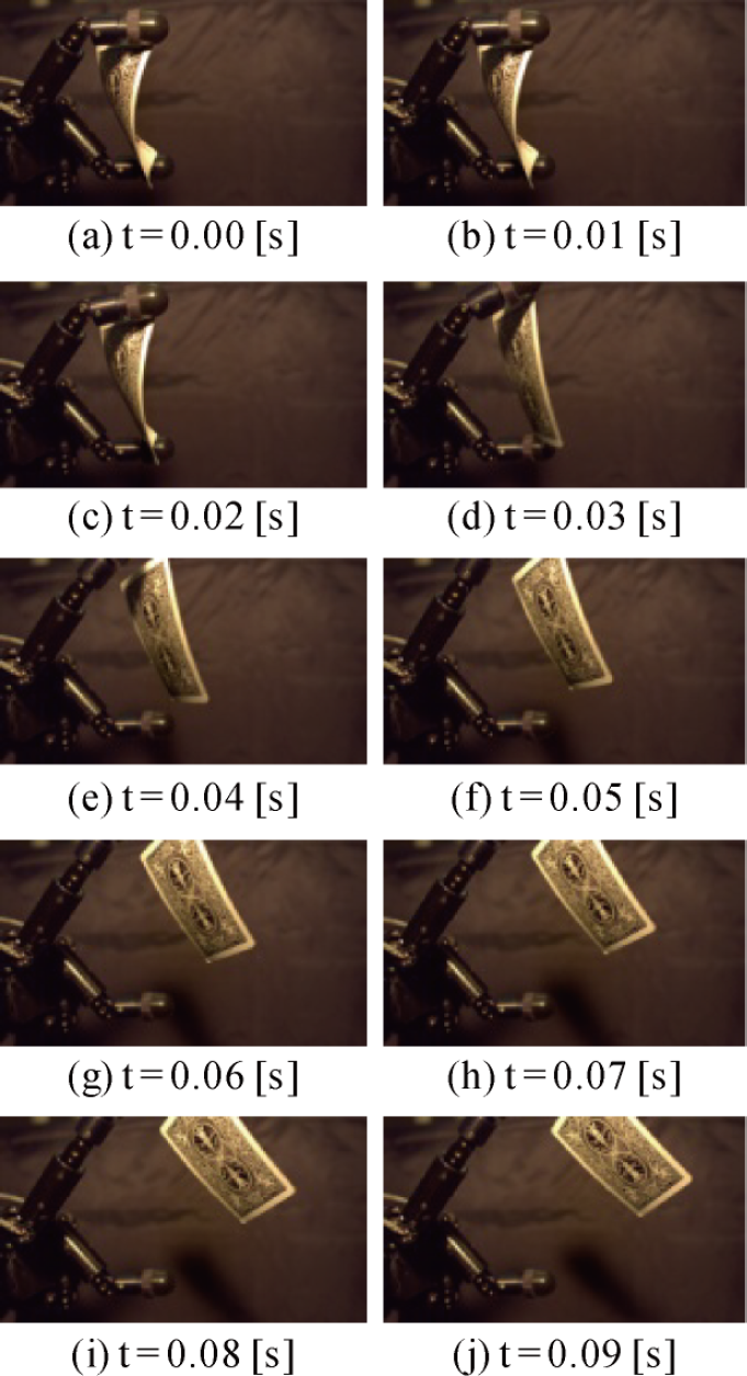
We show an experimental result of the flight of one card. The card's flight can be performed by the instant opening of the upper finger, but not by using the slippage phenomenon.
The experimental result of the flying card is shown in Fig. 11. This result can be captured using a high-speed camera system (Phantom v6.3) at 1,000 fps. These figures are written out every 0.01 s. Fig. 12 shows a composite photograph of the result as shown in Fig. 11.
In addition to the photographs, we analysed the trajectory of the flying card using the image processing technology. From the experimental result as shown in Fig. 10, the trajectory of the centre position of the flying card can be calculated as follows.
The centre positions of the card can be derived by using the image moments,

where x g and y g are image centre positions in the horizontal and vertical directions, respectively. M ij is the image moments given by

where f(x, y) is equal to 0 or 1, because the image is a binary image. In this calculation, since the inside of the card is assumed to be white in colour, f(x, y) of the card area is equal to 1.

Continuous photographs of experimental result of card flicking
The dotted lines in Fig. 10 illustrate the experimental data obtained by the above calculations for the results as shown in Fig. 11 and Fig. 12. We discuss the simulation result and the experimental result in the next section.
Comparing the simulation result with the experimental result as shown in Fig. 10, both centre positions of the card are almost the same. As a result, the simulation model and the estimated spring constant of the card can be confirmed as valid. Therefore, it can be considered that we can fly the card to a desired location by using the model to simulate the card's trajectory.

Continuous photographs of the experimental results of card flicking (close-up view)
Since we neglect the air drag in this model, the error between the simulation and the experiment after 0.15 s is shown in Fig. 10(c). Taking the effect of the air drag into account will produce a more precise estimated trajectory of the flying card.
In Section 4.3, we derived the spring constant of the card based on the experiment of the card's vibration, and simulated the trajectory of the flying card with the estimated spring constant. As a result, we confirmed the validities of the identification method of the spring constant and the simulation model of the flying card. From these methods, we can calculate the trajectory of the flying card and estimate a catching point for the card.
Consequently, we can catch the flying card with another robot hand. Moreover, we can improve the catching success rate by using high-speed visual feedback [18]. We can also execute a magic trick called “spring” by using the high-speed robot system and the proposed method.
In this section, we show the experimental results of the card flicking manipulation using the high-speed robot system as shown in Fig. 2. Fig. 13 shows continuous photographs of the experimental result of the card flicking using the high-speed multifingered robot hand with the proposed method. Fig. 14 shows close-up views of the continuous photographs of the experimental result. As can be seen from Figs. 13 and 14, card flicking was successfully achieved with good dexterity. It can be seen from Fig. 14 that the card flicking can be carried out at high-speed using the high-speed finger vibration, and that slippage occurs between the card and finger. The videos of the experimental results can be viewed at our website [31].
In [18], we achieved the card magic trick “spring” with the proposed method and the high-speed visual feedback. When the card enters the box, a reaction force is generated if the card collides with the box, which sometimes causes the card to jump back out of the box. This problem is not a critical issue in this research, and the success rate even with this problem was about 80%.
Conclusion
In this study, as one example of the manipulation of elastic objects, we performed card flicking by using a high-speed multifingered robot hand system. We proposed a strategy utilizing finger vibration for flicking the card. Based on the proposed strategy, we carried out the card flicking by using the strain energy occurring with card deformation. Furthermore, we analysed the slip condition and the transition from the strain energy to the kinetic energy during card flicking. We also discussed the estimation of the spring constant of the card. Then we calculated the velocity of the card with the transition analysis, and simulated the card's flight based on the parabolic motion model. Finally, we showed successful experimental results that validated the effectiveness of the proposed strategies.
In the future, we plan to realize more dexterous manipulations of cards. Fn particular, we will attempt to perform card tricks using the slippage between the card and the robot hand's finger with the proposed method, and a high-speed motion of the robot hand (which is beyond human motion) by using high-speed visual and tactile feedback. At present, we have achieved dynamic, high-speed manipulation using high-speed visual and tactile sensory feedback [28]. The high-speed visual and tactile feedback technique is important for achieving robust high-speed and dexterous manipulations [28] and improving the success rate of a task effectively. Thus, we will propose a high-speed sensory feedback control scheme in order to achieve these goals.