
Abstract
In this article, we present the mechanics and algorithms to compute the set of feasible motions of an object pushed in a plane. This set is known as the motion cone and was previously described for non-prehensile manipulation tasks in the horizontal plane. We generalize its construction to a broader set of planar tasks, such as those where external forces including gravity influence the dynamics of pushing, or prehensile tasks, where there are complex frictional interactions between the gripper, object, and pusher. We show that the motion cone is defined by a set of low-curvature surfaces and approximate it by a polyhedral cone. We verify its validity with thousands of pushing experiments recorded with a motion tracking system. Motion cones abstract the algebra involved in the dynamics of frictional pushing and can be used for simulation, planning, and control. In this article, we demonstrate their use for the dynamic propagation step in a sampling-based planning algorithm. By constraining the planner to explore only through the interior of motion cones, we obtain manipulation strategies that are robust against bounded uncertainties in the frictional parameters of the system. Our planner generates in-hand manipulation trajectories that involve sequences of continuous pushes, from different sides of the object when necessary, with 5–1,000 times speed improvements to equivalent algorithms.
Keywords
1. Introduction
A motion cone is the set of feasible motions that a rigid body can follow under the action of a frictional push. We can think of it as a representation of the underactuation inherent to frictional contacts. Since contacts can only push, and since friction is limited, a contact can move an object only along a limited set of rays. The concept was introduced by Mason (1986) for a point contact in the context of a planar horizontal pushing task.
Motion cones are a practical geometric representation that abstracts the algebra involved in simulating frictional contact dynamics, and provides direct bounds on the set of feasible object motions. A contact force on the inside (or boundary) of the friction cone produces sticking (or slipping) behavior, and leads to motion rays on the inside (or boundary) of the motion cone. Lynch and Mason (1996) generalized the construction of motion cones to line contacts in a horizontal plane. They used them to plan stable pushing trajectories without having to deal explicitly with the complexities of the complementarity formulations of contact dynamics (Chavan-Dafle and Rodriguez, 2017; Posa et al., 2014; Stewart and Trinkle, 1996). Since then, motion cones have been the basis of several efficient planning and control strategies for planar manipulations on a horizontal support surface (Dogar and Srinivasa, 2010; Erdmann, 1998; Hogan and Rodriguez, 2016; Zhou and Mason, 2017).
This article studies the construction of motion cones for a broader set of planar pushing tasks, moving beyond the horizontal plane, and including the effect of gravity. In particular, we highlight the case of prehensile manipulation in the vertical plane where gravity, or other possible external forces, alter the dynamics of the contact interactions between an external pusher and a grasped object. In this article, we show that motion cones are an effective representation to capture the coupled gripper–object–environment mechanics, which is critical for efficient simulation, planning, and control.
We present four main contributions.
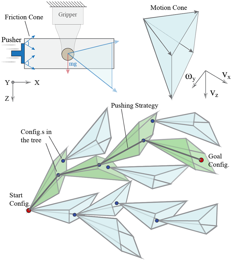
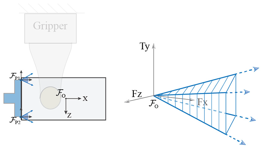
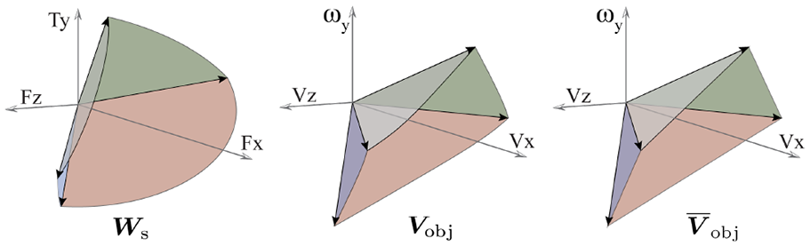
(Top) Example friction cone and motion cone of an object moving in the vertical plane. The pusher can move the object along any direction
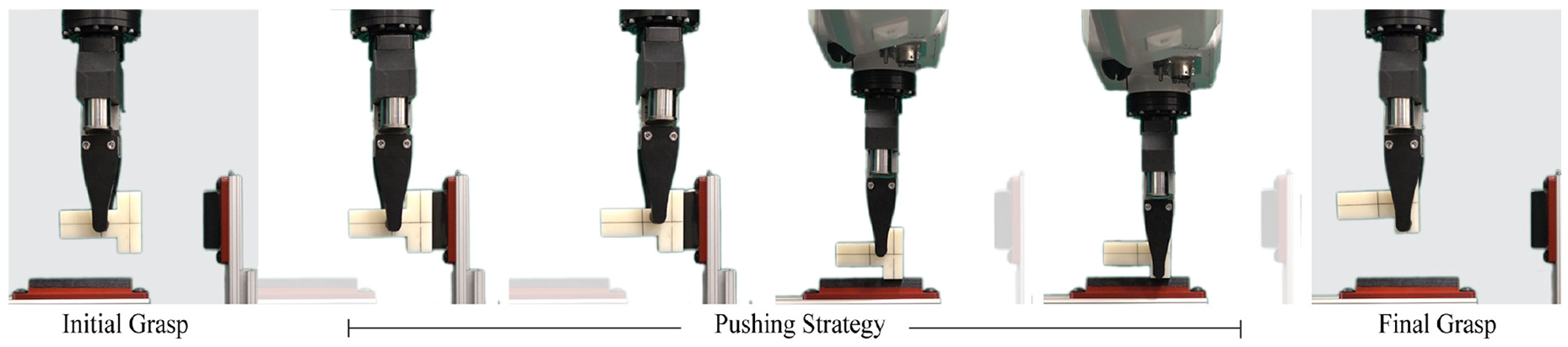
Manipulating a T-shaped object in a parallel-jaw grasp by pushing it against features in the environment. The manipulation is shown from a side view.
The generalization of motion cones to interactions with external forces such as gravity opens the door for efficient and robust planning of in-hand manipulation that respects, and exploits, the basic principles of frictional rigid-body contact interactions: Newton’s second law, Coulomb’s friction law, the principle of maximal dissipation, and the rigidity of rigid bodies.
1.1. Structure of the article
In this article, we describe the mechanics and algorithms involved in using motion cones. When possible, we use both the languages of algebra (for implementation) and geometry (for intuition) to describe them.
The article can be divided into four main parts: (i) mechanics of planar pushing; (ii) construction, computation, and validation of motion cones; (iii) using motion cones to plan in-hand manipulation; (iv) different mechanisms to increase the reliability of motion cones.
1.1.1. The mechanics of planar pushing
This is the basis of the mechanics analysis in the article and is reviewed in detail in Section 3. We show how the motion of a pushed object is governed by three key laws (described in three subsections):
the frictional interaction at the contact between an object and a supporting plane, the limit surface;
the frictional interaction at the contact between the object and the pusher; when the contact is a point, Coulomb’s law defines a friction cone; when the contact is a line or more complex, it defines a generalized friction cone;
the force balance imposed by Newton’s second law.
These three constraints define the set of possible force equilibria between the gripper, object, and environment.
1.1.2. Construction, computation, and validation of motion cones
In Section 4 we show how a particular choice of pusher motion, alongside the principle of maximal dissipation, i.e., relation between the friction and velocity of a sliding object, determines the motion of the pushed object. The set of object motions for all possible pusher motions defines the motion cone. Section 4 describes how to compute motion cones for the cases of an object pushed in the horizontal plane (review) and in the vertical plane with gravity (contribution). In Section 5 we provide an analytic expression for the motion cone as well as an approximation in the form of a polyhedral motion cone, which will be key to using them in a fast planning framework. At the end of this section we detail efforts to verify experimentally the validity of motion cones for three different task configurations, i.e., three different combinations of grasps and prehensile pushes.
1.1.3. Motion cones for planning in-hand manipulation
In Section 6 we describe how to use motion cones to manipulate grasped objects by pushing them against contacts in the environment. Motion cones directly describe the set of directions along which a grasped object can be displaced for a given external contact. In practice, we compute motion cones in real-time and use them to efficiently sample feasible regrasps in an RRT*-based planning framework. In Section 7 we show different examples of planned and executed planar in-hand regrasps.
1.1.4. Robustness of motion cones
Finally, we explore different ways to improve the reliability of motion cones. Section 8 shows that either a conservative approximation of motion cones, or a careful selection of the orientation of the task with respect to gravity, are sufficient to yield mechanical robustness with respect to variations in the available friction at the contacts and the gripping force.
We provide a video summarizing our approach at https://youtu.be/tVDO8QMuYhc.
1.2. Assumptions of the approach
This article presents a model-based approach to planar in-hand manipulation of grasped objects. The approach relies on the following assumptions and representations.
The planning framework proposed in this article uses the mechanics of pushing, captured in the form of motion cones, to generate a sequence of external pushes that moves the object from the initial to the final grasp. In our implementation, the external pushes are executed by a robot forcing the grasped object against fixed features in the environment. These pushes could also abstract the interactions with a second robot arm or with extra fingers in a multi-finger gripper.
Figure 3 shows the schematic from the planner’s perspective: in the planning phase, we imagine the alternate perspective where the parallel-jaw gripper is fixed in the world and the environment is a “virtual” pusher with full three-degree-of-freedom (3DOF) mobility in the manipulation plane pushing the grasped object. Planning external pushes is then equivalent to planning the motion of the virtual pusher to achieve the desired regrasp. The “virtual” pusher motion is then rendered in the real world by instead moving the gripper.
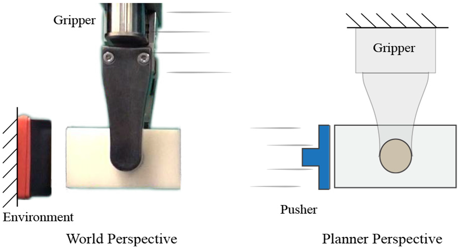
(Left) An object held in a parallel-jaw gripper is pushed against a fixed feature in the environment. (Right) The planner models this interaction as if the object is held by a fixed gripper and pushed by a moving environment, i.e., a pusher.
2. Related work
Planning and control through contact is a central topic in robotic manipulation research. A rigid-body contact is modeled as a series of constraints on the possible motions and forces at contact. A particular contact mode, either sticking or sliding, invokes a specific set of constraints on the motions and forces at contact. Stewart and Trinkle (1996) and Trinkle et al. (1997) showed that a general rigid-body dynamics problem with hybrid sticking/slipping dynamics at contact interactions can be modeled as a complementarity problem.
Recent work on trajectory optimization and manipulation planning has shown that it is possible to reason about hybrid stick/slip contact modes and plan trajectories through continuous contact with complementarity constraints (Chavan-Dafle and Rodriguez, 2017; Posa et al., 2014). An alternative approach is to replace the hard complementarity constraints by optimization-friendlier soft-constraints, which yields a faster planning and control framework (Kumar et al., 2014; Todorov et al., 2012). These methods, though broad in their scope of application, often have to compromise between computational efficiency and the realism of contact dynamics (Kolbert et al., 2016).
In contrast, a pivotal theme in the non-prehensile manipulation literature is to identify application-specific and compact representations of contact constraints and the mechanics of the task. Goyal (1989) introduced the concept of a limit surface, a compact mapping from the friction wrench between an object and its support surface and the sliding twist at contact. Mason (1986) studied the mechanics of pushing and proposed the concept of the motion cone. These two fundamental geometric constructions provide direct force–motion mappings for contact interactions and have facilitated efficient planning and control techniques in non-prehensile manipulation (Dogar and Srinivasa, 2010, 2011; Hogan and Rodriguez, 2016; Lynch et al., 1992; Lynch and Mason, 1996; Zhou and Mason, 2017).
Lynch and Mason (1996) extended the idea of motion cones to a line pusher on a horizontal surface and showed its application for planning robust pushing strategies for which the pusher contact sticks to the object. Dogar and Srinivasa (2011) demonstrated the application of motion cones in the push-grasping framework to plan pushes that capture an object before grasping it. Hogan and Rodriguez (2016) and Zhou and Mason (2017) exploit the direct action–effect mapping in motion cones to develop efficient planning and control techniques for pushing an object on a horizontal plane.
Some recent work focuses on other types of manipulation primitives. Shi et al. (2015) demonstrated dynamic in-hand manipulation planning in a parallel-jaw grasp by exploiting inertial forces. With a pre-defined contact mode sequence at the fingers and a limit surface approximation for the force-motion interaction at the fingers, they derive a control law that can move the object to the goal grasp through a sequence of fast accelerations and decelerations. Similar approaches are explored for planning and controlling in-hand manipulations by actively using gravity (Viña B et al., 2016) or dynamic motions (Holladay et al., 2015; Hou, 2017; Sintov and Shapiro, 2016).
Sundaralingam and Hermans (2017) proposed a purely kinematic approach for in-hand manipulation based on trajectory optimization with a multi-finger gripper. They assumed that the fingers on the object do not slip and impose soft constraints that encourage the minimization of finger slip. By assuming all finger contacts to be sticking, they bypassed the need for modeling the dynamics of contacts and obtained fast kinematic plans.
In recent work (Chavan-Dafle and Rodriguez, 2018b), we presented a sampling-based planning framework for in-hand manipulations with prehensile pushes, where the pusher contact is forced to stick to the object using the mechanics of the task. The plans are discrete sequences of continuous pushes that respect friction, contact, and rigid-body constraints.
These promising results on in-hand manipulation, which are limited to certain types of manipulation primitives, motivate us to extend the concept of motion cones to more general pushing tasks. Motion cones provide direct bounds on the set of possible object motions and can be used in sampling-based frameworks to guide sampling, or as a set of direct constraints in a trajectory optimization framework.
3. Mechanics of planar pushing
Figure 4 shows four different cases of planar pushing. In case (a), the pusher force is the only external force on the object in the manipulation plane. However, in the other cases, a component of gravity is also present. The concept of motion cones, as originally studied by Mason (1986) and Lynch and Mason (1996), is limited to case (a). The extension of the mechanics of motion cones that we present in this article is valid for all cases in Figure 4.
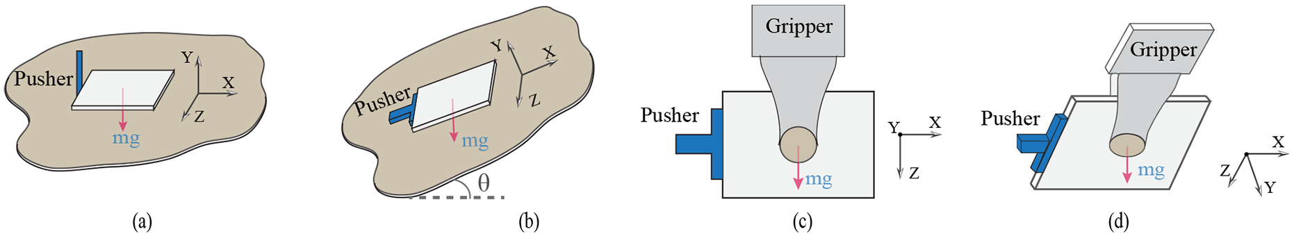
Pushing an object (a) on a horizontal surface, (b) on an inclined surface, (c) in a grasp in the gravity plane, and (d) in a grasp in a tilted plane.
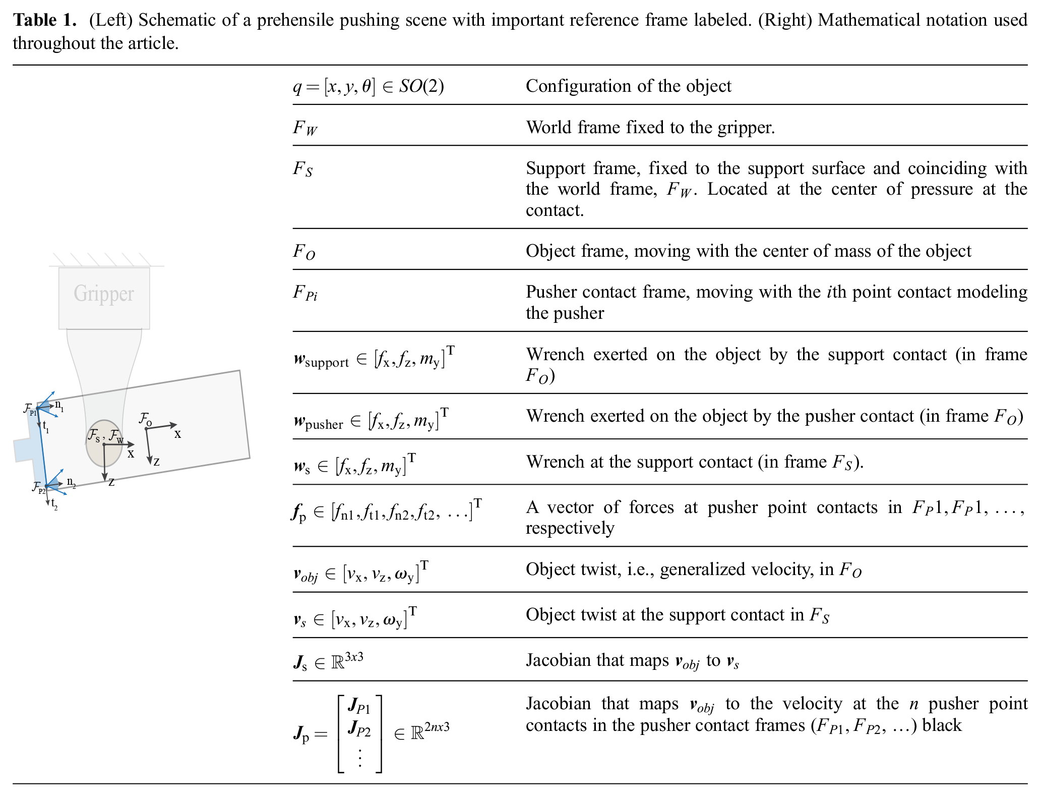
In this section we discuss the mechanics of pushing an object in a plane. First, we review the fundamental concepts, namely, the limit surface (Goyal, 1989), and the generalized friction cone (Erdmann, 1994). These tools will serve as building blocks for modeling the force–motion interaction at the contacts involved in pushing manipulations. Table 1 lists the notation used within the rest of the article.
3.1. Limit surface
The limit surface is a common construction to model the frictional interaction at a planar patch contact. In this article, we use the limit surface to model the force–motion interaction between an object and a support contact. In cases (a) and (b) in Figure 4, the surface on which the object rests is the support contact. In cases (c) and (d), the gripper fingers are the support contacts. As summarized in Table 1, for object motions in the manipulation plane, the resultant friction wrench
(Left) Schematic of a prehensile pushing scene with important reference frame labeled. (Right) Mathematical notation used throughout the article.
Goyal (1989) defined the boundary of the set of all possible friction wrenches that a contact can offer as the limit surface. Each wrench on the boundary of the limit surface corresponds to a different sliding motion of the object on the support plane. Based on the principal of maximum dissipation, the perpendicular to the limit surface at a given wrench provides the corresponding generalized velocity of the object (Goyal, 1989).
Related to the limit surface, the gravito-inertial wrench cone (GIWC) is a geometric construct in legged locomotion literature. However, the embedding of the principal of maximum dissipation into the limit surface construction provides the information of the sliding velocity at the contact, which GIWC cannot. 1
The limit surface is smooth and convex if the support force distribution is finite everywhere. Howe and Cutkosky (1996); Xydas and Kao (1999) showed that an ellipsoidal approximation allows for a simpler representation of the limit surface geometry. In this article we assume an ellipsoidal approximation of the limit surface, which has been shown to be computationally efficient for simulating and planning pushing motions (Dogar and Srinivasa, 2011; Lynch and Mason, 1996; Shi et al., 2015; Zhou and Mason, 2017).
Let

where, for isotropic friction,
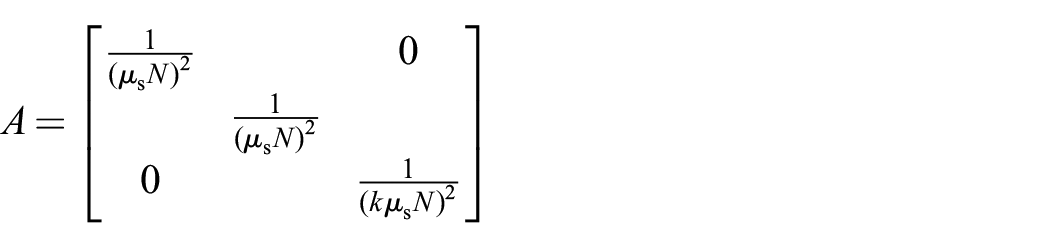
such that
Note that the geometry of the limit surface is defined by the area and pressure distribution at the contact and scaled by normal force and friction coefficient at the contact.
When the object slides on the support contact, the friction wrench (
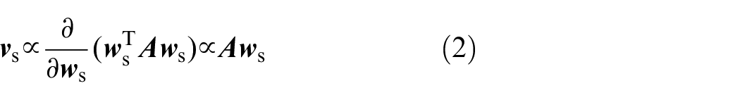
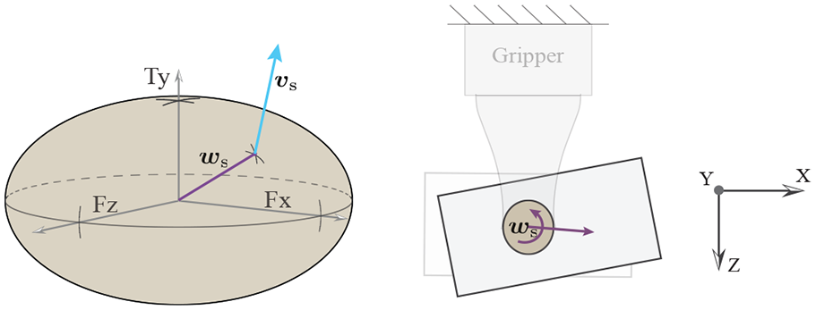
(Left) Ellipsoidal approximation of the limit surface at the finger contact. For a wrench
Conversely, if the object twist at the contact (
Since
Given that
Here,
The force–motion mapping we have discussed so far is in the support contact frame. From (2) and (4), the direction of the object twist in the object frame (

where
3.2. Generalized friction cone
Coulomb’s friction law is the basis for many of the models used to simulate frictional interaction between two rigid bodies. A Coulomb friction cone establishes the relationship between the normal force and the maximum friction force at a point contact.
Erdmann (1994) introduced the concept of the generalized friction cone (
(Left) The line pusher contact in this example is modeled with two point contacts. The pusher contact frames and the object frame are drawn in the figure. (Right) The generalized friction cone of the pusher is the object frame representation of the set of forces the two point contacts can offer collectively.
We model the friction between the pusher and the object by constructing the generalized friction cone:

where
We model the interaction between support-and-object (limit surface) and between pusher-and-object (generalized friction cone) differently due to the different geometries and expected pressure distributions. For the support–object interaction, the ellipsoidal approximation to the limit surface provides a compact force-motion relationship at a support contact where we expect a constant normal force distribution during the manipulation. Whereas, the generalized friction cone is a better approach for modeling the friction at the pusher contact where we can have varying normal force distribution for every instantaneous push.
Now, with the chosen models for frictional contact, we formulate the mechanics of pushing in a plane.
3.3. Mechanics of Pushing
The motion of the pushed object is in accordance with the net wrench acting on the object. Under the quasi-static assumption, which is appropriate for slow pushing operations, the inertial forces on the object are negligible and force balance requires:

Here, Equation (7) is written in the object frame located at the center of gravity,
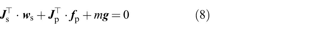
Equations (8), (6), and (5) define the system of equations to solve to determine the velocity of the object
Generating a motion plan for a given pushing manipulation task, e.g., moving an object on a ground or in a grasp, involves building a continuous series of instantaneous feasible object and pusher motions that satisfy the mechanics of pushing at every instant. In a trajectory optimization framework, this translates to including the complementarity constraints from the dynamics of pushing into the optimization problem and optimizing for the series of object–pusher states. In a sampling-based framework this translates to sampling instantaneous pusher–object motions that comply with (8), (6), and (5). Checking their feasibility involves solving the mechanics of pushing and keeping track of the pusher–object state including the possibility of sliding between them.
Either way, solving the mechanics of pushing to predict the pusher–object motion and slipping/sticking at contacts is computationally expensive (Hogan and Rodriguez, 2016; Posa et al., 2014). A direct action–effect mapping, i.e., the relationship between the pusher motion and object motion, avoids the burden of solving the hybrid mechanics of pushing. The existence of such a mapping is the key motivation of this article, described by the motion cone construction that we study in the following section.
4. Motion cones for planar pushing
In this section, we present the general formulation for defining a motion cone for planar pushing. We discuss the nature of the constraints that define the motion cone for pushing on a horizontal surface (Figure 4(a)) and for more general pushing scenarios (Figure 4(b)–(d)). We highlight some of the peculiarities of the case of pushing an object in the gravity plane, which forms the basis for the computation and application of the motion cones in the following sections.
The motion cone is the set of instantaneous object velocities that a pusher can impose on the object using the frictional interaction between them. If the pusher moves along a twist inside the motion cone, the contact between the object and the pusher sticks and the object follows the pusher motion. If the pusher moves along a twist outside the motion cone, there is sliding at the pusher–object interface and the object moves along a twist on the boundary of the motion cone. While the pusher has full control to move with any velocity, it can impose only a set of object velocities defined by the motion cone.
Mathematically, a motion cone is the largest set of object motions for which the net required wrench for the object motion can be balanced by a wrench on the interior of the generalized friction cone of the pusher. It is the set of object velocities for which constraint (8) holds true while
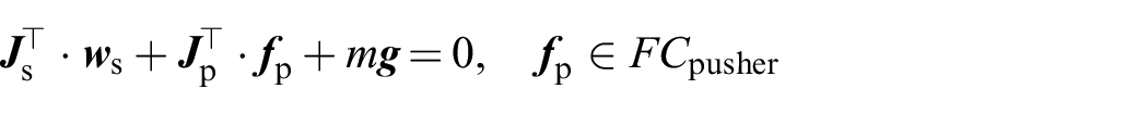
Using (4) and (6), we can rewrite the previous equation as
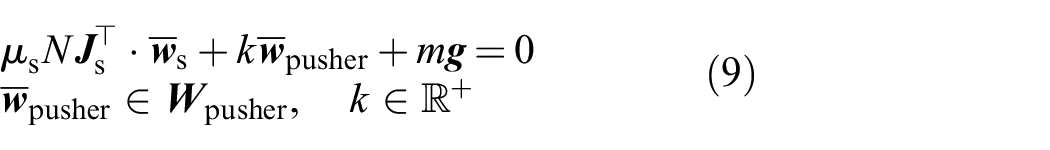
where k is the magnitude of the pusher force and
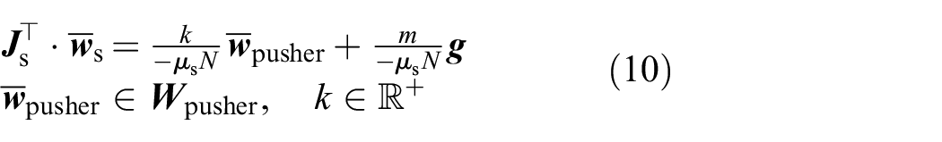
Using (5) we can map the support contact unit wrench
4.1. Motion cone for pushing on a horizontal surface
The presence of an external force other than the pusher force (such as the gravitational force) in the plane of motion complicates the mechanics and the structure of the motion cone. To explain this effect in detail, we will first consider the case of pushing an object on a horizontal surface where there is no such additional force.
For the case of pushing on a horizontal plane,

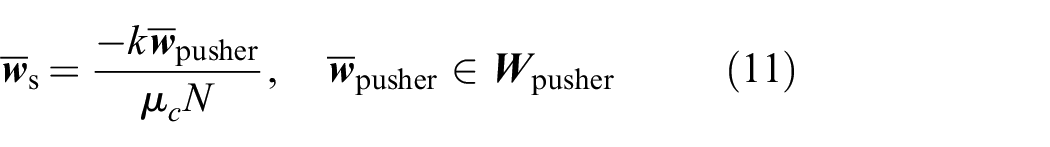
The set of valid support contact wrenches that satisfy (11) is the negative of the generalized friction cone of the pusher, i.e.,
Note that for the case of pushing on a horizontal surface,
For more general pushing tasks, however,
Note that the case in Figure 4(b) can be modeled in the same way as (c) except the Jacobian
4.2. Motion cone in the gravity plane
For a case similar to Figure 4(c), but in a gravity-free world, we can simplify Equation (10) by omitting the gravity term. We can then compute a convex polyhedral motion cone similar to that in the horizontal pushing case, but while taking the Jacobian
By rearranging (9), we see that an instantaneous object motion is feasible if the net wrench required for the object motion falls inside the generalized friction cone of the pusher:

The gravitational wrench
Proof. For a motion inside a gravity-free motion cone, the support/grasp wrench direction lies on the interior the generalized friction cone of the pusher, i.e.,
To make a push inside the gravity-free motion cone also stable in a scenario with gravity, the unit grasp wrench can be scaled such that the net pusher wrench required for the desired push falls inside/on the generalized friction cone of the pusher.
A similar argument can be made for determining a minimum friction threshold at the finger contacts. For a given normal force N, we can analytically find the bounds on
Proof. From (12) and Proposition 1, as the grasping force increases, the net wrench for more twists or velocities from the gravity-free motion cone fall inside the generalized friction cone of the pusher.
In the gravity-free case,
As

Then, for all

Thus, the set of object motions
We see that, in theory, we can make any object motion in the gravity-free motion cone feasible under gravity by increasing the grasping force. With increased grasping force, more motions in the gravity-free motion cone are stable under gravity and become part of the motion cone. In practice, however, grippers have limited grasping force and often lack online force control. Moreover, by limiting to the gravity-free motion cone, we omit object motions outside the gravity-free motion cone that otherwise would be feasible when considering the gravitational force on the object. Therefore, both for practical reasons and for capturing the rich mechanics of prehensile pushing, we need to find the motion cone under gravity for a given grasping force.
Note that for the case of pushing the object on a horizontal plane, the motion cone is invariant to the support normal force. However, for pushing on a support plane at an angle, as in Figure 4(b), a component of gravitational force acts in the manipulation plane and we do not have a freedom to change the support normal force, so computing the motion cone for a fixed support normal force is essential for these non-prehensile manipulation cases as well.
5. Computation and experimental validationof motion cone
In this section we present a closed-form computation of the object motion cone in the gravity case for a given grasping force and friction parameters. We discuss the graphical intuition for the mechanics and the computation of the motion cone. A large set of pushing experiments in different object–pusher configurations demonstrate that the analytically found motion cones characterize the set of feasible object motions with an average of
5.1. Analytical computation
For a known
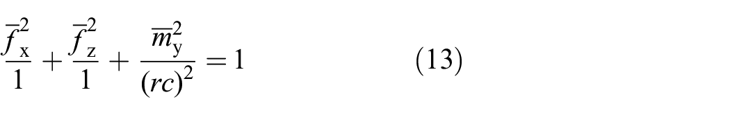
Constraints (10) and (13) can be solved together analytically to find
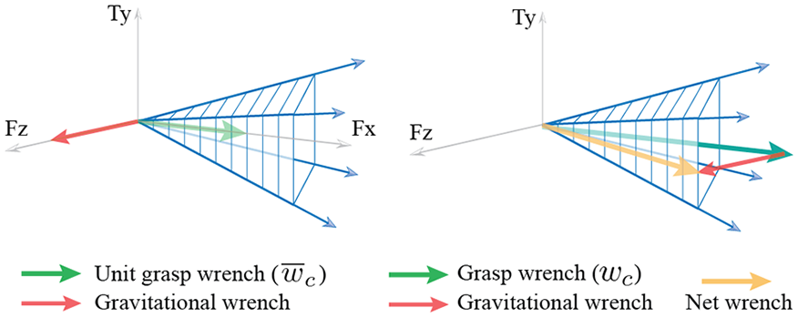
Figure 8 illustrates the process for solving the constraints (10) and (13) together to compute the wrench cone
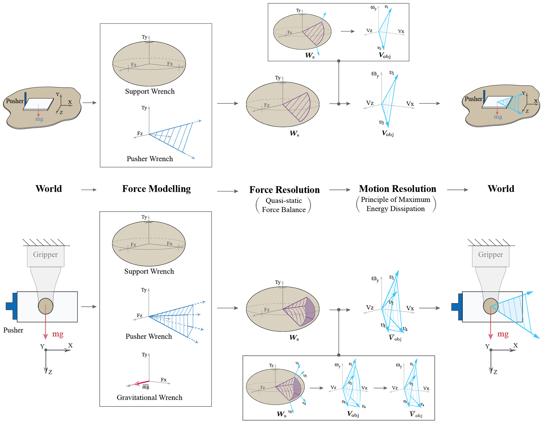
Graphical illustration of the motion cone construction procedure applied to two different planar pushing systems: (top) pushing an object on a horizontal plane with a point pusher and (bottom) pushing an object in a grasp in the gravity plane. From left to right, the construction steps portray modeling of the forces involved in the task (force modeling), solving for the set of force-balance solutions in wrench space (force resolution), and finally computing the set of object twists corresponding to the force-balancing solutions (motion resolution). This set of object twists is the motion cone.
Figure 8(top) shows the computation of the motion cone for pushing an object on a horizontal support plane with a point pusher. As discussed in Section 4.1, from (11), when there is no external wrench other than the pusher wrench acting on the object, the motion cone computation simplifies and
In more general cases where additional external forces, such as the gravitational force, are present in the manipulation plane,
The analytically computed wrench cone (
5.2. Polyhedral approximation to the motion cone
As an object is pushed in a grasp, the position of the finger contacts in the object frame change, and consequently
As the boundary surfaces of the motion cone have low curvatures, we propose a polyhedral approximation (
Solve (10) and (13) simultaneously to get
Define the set of
Map
5.3. Experimental validation of the motion cone
Figure 10 shows our manipulation platform equipped with an industrial robot arm (ABB IRB120), a parallel-jaw gripper (WEISS WSG32), two geometric features in the environment that act as pushers, and a Vicon system (Bonita) for accurate object tracking.
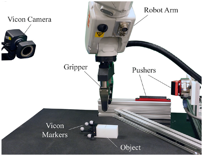
Experimental setup used for the data collection for motion cone validation as well as for the regrasp examples in Sections 7 and 8.
The theory from Section 4, states that the pusher sticks to the object for the pusher twists inside the motion cone while the twists outside the motion cone will result in slipping at the pusher contact. To evaluate the experimental validity of the polyhedral approximation of the motion cone, we collected data for the slip observed at the pusher contact for a variety of experimental settings.
Using the rectangular prism object listed in Table 3, we conducted six experiments across three configurations as shown in the leftmost column of Table 2. The first two configurations use the side pusher and the grasp is offset from the center of mass of the object by
We experimentally validated the polyhedral approximation of the motion cone across three configurations by characterizing thousands of random prehensile pushes by the slip observed at the pusher contact. The pushes that did slip are shown in gray, while those that did not are shown in black. For each configuration, we utilized a grasping force of
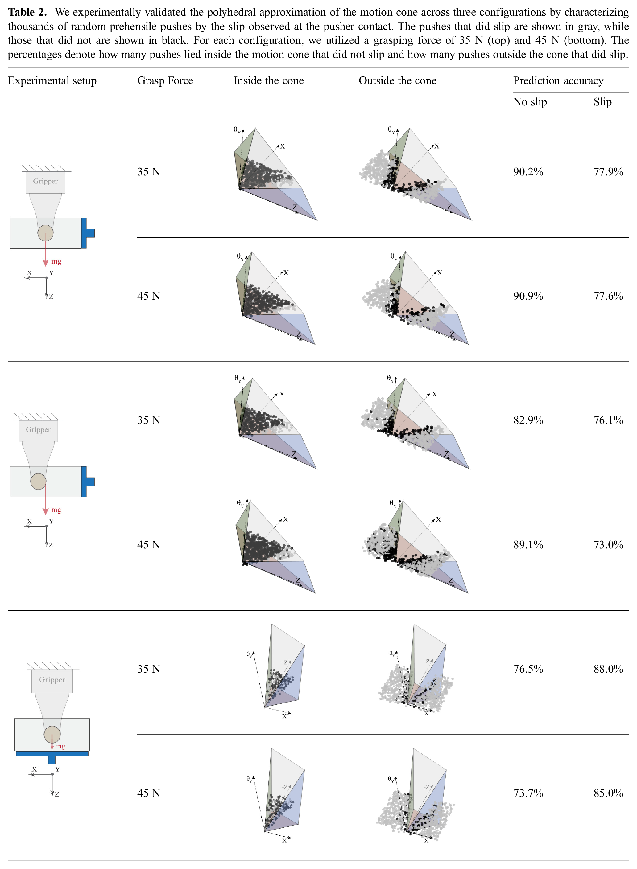
For each configuration, we conducted two experiments, first with a grasping force of
Owing to kinematic constraints of the robot and the workspace, we limit the sampled pushes to the space of
For each experiment, Table 2 lists two accuracy percentages. The first denotes percentage of pushes that lie inside the motion cone that did indeed stick, as predicted. The second denotes the percentage of pushes that lie outside the motion cone that did slip, as predicted. The analytically computed polyhedral approximation to the motion cone classifies the stick/slip at the pusher contact and characterizes the feasibility of the object motions with an average accuracy of
We observe that the mislabeled pushes are close to the boundaries of the motion cones. There could be a few reasons for these inaccurate predictions. The variation in the measured friction at the fingers or pusher contacts and variation in the grasping force can make the predictions close to the boundaries of the motion cone inaccurate. The motion cone construction builds upon the approximations of friction models at finger as well as pusher contacts and rigid-body assumptions. Therefore, any unmodeled dynamics and compliance at the contacts affect its validity, especially close to the boundary of the motion cone. Section 8 explores different strategies to make the predictions more reliable.
6. Planning in-hand manipulations viamotion cones
Motion cones abstract the algebra involved in solving the mechanics of pushing and provide direct bounds on the feasible object motions with pushing. For pusher motions inside the motion cone, the contact between the pusher and the object remains sticking, and the object follows the pusher. For pusher motions outside the motion cone, there is slipping at the pusher contact and the object motion is on the boundary of the motion cone. This mapping between the motions of the pusher and the object along with sticking/slipping contact mode resolution can be used for fast and efficient planning of pushing tasks.
In this section, we demonstrate the application of motion cones for planning in-hand manipulations with prehensile pushes. In particular, we constrain our planner to build manipulation strategies for which the pusher contact sticks to the object. Lynch and Mason (1996) studied pushing motions for which the pusher sticks to the object when pushing on a horizontal surface, which they referred to as stable pushing. We call our equivalent prehensile version stable prehensile pushing (Chavan-Dafle and Rodriguez, 2018b).
6.1. Problem formulation
An object is grasped in a parallel-jaw gripper and manipulated in the gravity plane by pushing it against contacts in the environment.
For the problem setup, we assume the following information about the manipulation system.
Object geometry and mass.
Initial and goal grasp of the object, specified by the locations of the finger contacts.
Gripping force.
Set of possible pusher contacts in the environment, specified by their geometries and locations in the object frame.
Coefficients of friction of all contacts.
6.2. Planner framework
Our proposed planning framework works at two levels. At the high level, a T-RRT*-based planning architecture samples the configuration space of different grasps, similar to earlier work in Chavan-Dafle and Rodriguez (2018b). At the low level, the planning tree is grown in the direction of the sampled grasp poses using the knowledge of locally reachable grasp poses in the form of motion cones.
For selective exploration, the T-RRT* framework relies on a transition test that filters the sampled configurations to prefer exploration in low-configuration-cost regions (Devaurs et al., 2016; Jaillet et al., 2010). We define the configuration cost as the distance of the grasp from the goal. The transition test guides the stochastic exploration towards the goal grasp, while allowing the flexibility to explore high-cost transitions if they are necessary to get the object to the goal.
For effective connections, the T-RRT* algorithm uses the underlying RRT* (Karaman and Frazzoli, 2011) framework to make and rewire the connections in the tree at every step such that the local cost of the nodes is reduced when possible. We define the cost of a node as the sum of the cost of the parent node and the cost of the push to reach the sampled node from the parent node. We set the cost of a push to
Let q denote the configuration of the object, i.e., the pose of the object in the gripper frame, which is fixed in the world. In this article, we consider planar manipulations in a parallel-jaw grasp, so the configuration space
Algorithm 1 describes our in-hand manipulation planner. Let
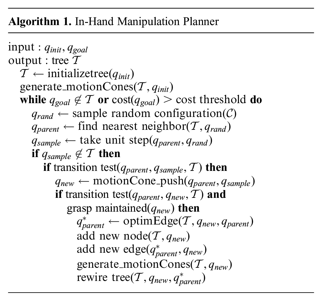
While the desired object pose is not reached within some cost threshold, a random configuration
Two important routines in Algorithm 1, particularly for this article, are generate_motionCones and motionCone_ push.
generate_motionCones computes the polyhedral motion cones for a given object configuration in the grasp for all possible external pushers using the procedure listed in Section 5.2. At every node, we will have the same number of motion cones as possible pushers and each motion cone represents the set of object configurations that can be reached from the current configuration using a specific pusher.
motionCone_push finds an object pose closest to the desired sampled pose
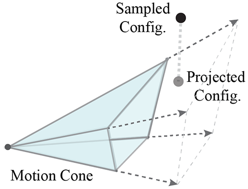
Since the sampled grasp configuration is outside the motion cone, it projected onto the motion cone. The projected configuration is selected to grow the planning tree.
Motion cones define the set of feasible pushes or, in other words, the set of reachable object configurations. Using motion cones as reachability bounds directly in the configuration space allows us to rapidly explore the configuration space of different object poses in the grasp and generate dynamically feasible pushing strategies for the desired in-hand regrasp.
7. Regrasp examples and experimental results
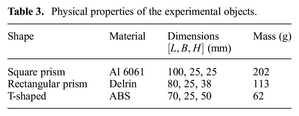
We evaluate the performance of our proposed planner with examples of a parallel-jaw gripper manipulating a variety of objects listed in Table 3. The initial pose of an object in the gripper is treated as
Physical properties of the experimental objects.
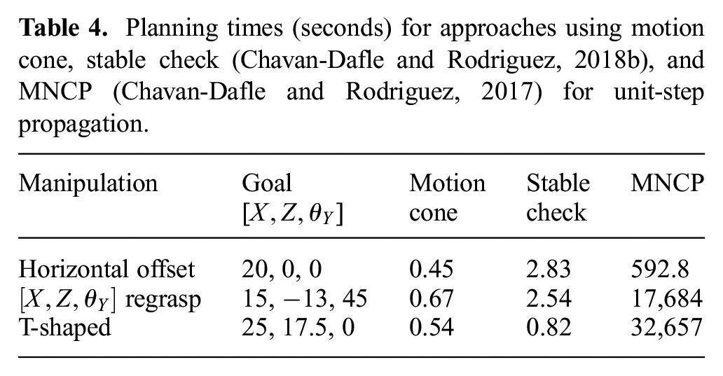
Planning times (seconds) for approaches using motion cone, stable check (Chavan-Dafle and Rodriguez, 2018b), and MNCP (Chavan-Dafle and Rodriguez, 2017) for unit-step propagation.
In all of the following examples, we assume three line pushers on the object, one on each of the side faces of the object parallel to the Z axis and one under the object parallel to the X axis. We use high friction line pushers, except in the first example, where we use low friction line pushers (Figure 12).
Simulation and experimental run for a pushing strategy to regrasp the aluminum object with low-friction pushers. In the simulation figure (top), the finger and pusher contacts are shown in green and magenta color, respectively.
7.1. Regrasping an object offset to the center
In this example, the goal is to regrasp the square prism horizontally 20 mm offset from the center. We use low-friction pushers first. Kolbert et al. (2016) showed that for a similar setting, if the object is pushed horizontally in the grasp, it slides down as it moves sideways in the grasp. For low-friction pushers, our planner generates a strategy where the object is first pushed up using the bottom pusher and then the side pusher is used to virtually keep the object stationary while the fingers slide up and along the length of the object as seen in Figure 12. This plan is similar to that found in Chavan-Dafle and Rodriguez (2017, 2018b).
When we replace the pushers with high-friction pushers (pushers with rubber coating), the planner estimates that the desired horizontal object motion lies inside the motion cone for the side pusher at the initial and all the subsequent grasp poses until the goal, i.e., simply pushing from the side is a valid pushing strategy as shown in Figure 13.
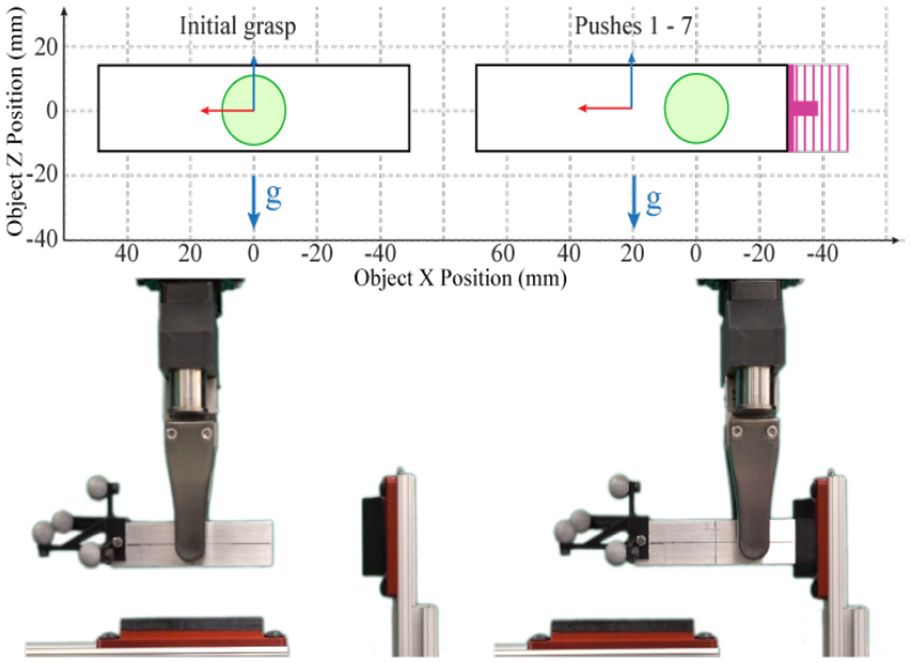
Simulation and experimental run for a pushing strategy to regrasp the aluminum object with high-friction pushers.
7.2. Regrasp in [
]
The goal in this example is to regrasp the rectangular prism requiring a net object motion in all three dimensions [
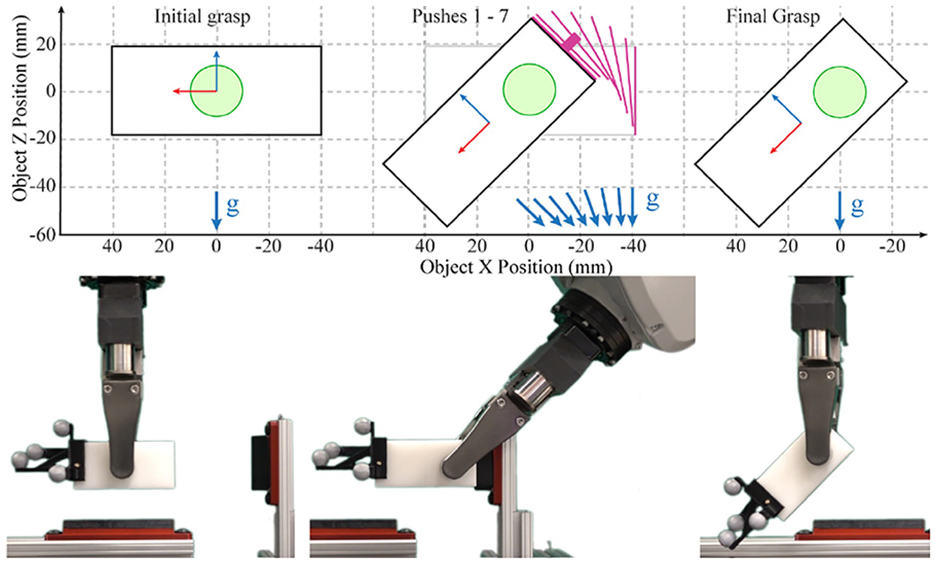
A pushing strategy for [
7.3. Manipulating a non-convex object
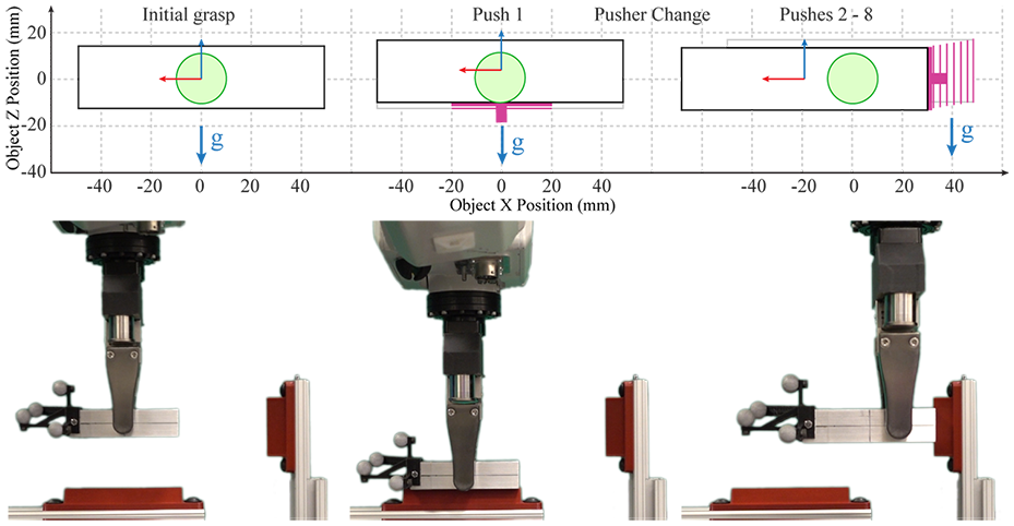
In this example, the goal is to regrasp a T-shaped object. The goal pose is such that a greedy approach to push the object directly towards the goal will result in losing the grasp on the object. As shown in Figure 15, our planner comes up with a pushing strategy that respects the geometric constraints of the problem and moves the object to the desired pose without loosing the grasp.
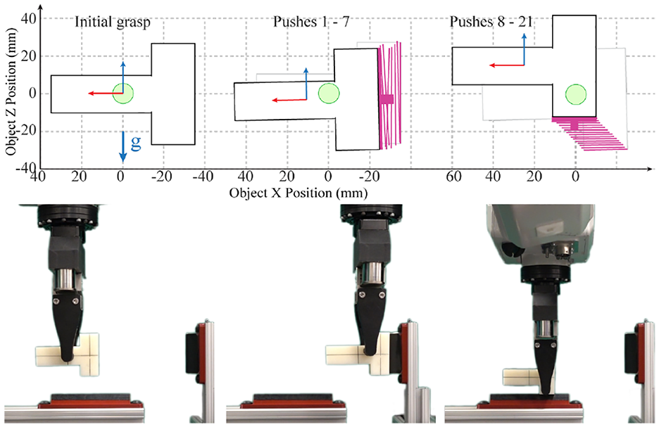
Simulation and experimental run to manipulate a T-shaped object. Snapshots of the experimental run are as shown in Figure 2.
8. Robust in-hand manipulations viamotion cones
Sections 6 and 7 describe an application of motion cones to plan in-hand manipulations with stable prehensile pushes. In this section, we discuss constraining the planning tree to propagate through a conservative interior of motion cones for increased robustness. We show that we can exploit the structure of motion cones to derive manipulation strategies that are robust against uncertainties in the friction parameters at the finger and pusher contacts, grasping force, and mass of the object.
8.1. Robustness to friction variation at the pusher–object contact
For a given object mass, given friction at the finger contacts, and given grasping force, the motion cone is a function of the friction at the pusher. For a higher friction coefficient, the generalized friction cone is wider and so is the motion cone. There is a monotonic relationship between the friction at the pusher and the volume of the motion cone. This relationship can be exploited to derive pushing strategies robust to uncertainty in the friction at the pusher.
Proof. Let

If an object motion is inside the motion cone, the net required wrench for the object motion lies inside the generalized friction cone of the pusher, i.e., repeating (12):

From (14) and (15),
Since the net required wrench lies inside the friction cone of the pusher, the object motion is inside the motion cone.
If there is uncertainty in the friction coefficient at the pusher, we can obtain a robust strategy by planning with the lower bound on the coefficient. The resulting strategy will produce the same net object motion in the grasp even if the true friction coefficient at the pusher is higher.
This property is also verified by our experiments from Section 5.3. For our experiment where we offset the grasp
8.2. Robustness to friction variation at the gripper–object contact
For a given friction coefficient at the pusher, the motion cone is a function of the object mass and the friction coefficient at the finger contacts, and the grasping force.
Unlike the monotonic relationship of the motion cone to the friction at the pusher, the dependence of the motion cone on the friction force at the fingers is not straightforward. For increased friction at the fingers, either by increasing the grasping force or by increasing the coefficient of friction, we do not necessarily obtain a wider motion cone. Instead the motion cone shifts towards the gravity-free motion cone as shown in Figure 16. At infinite friction at the gripper the motion cone is equal to the gravity-free motion cone as shown in Corollary 1.1. Therefore, some of the object motions inside the motion cone, particularly those that are feasible by exploiting gravity, may no longer be feasible.
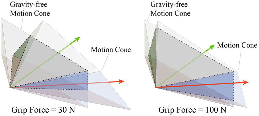
The motion cone shifts towards the gravity-free motion cone as the friction at the gripper increases due to the increased grip force. The intersection of the gravity-free motion cone and the motion cone is shown by the dotted region for the two grip forces. The motions inside the motion cone that are outside the gravity-free motion cone are feasible only by exploiting the gravitational force on the object (in Z direction). For higher friction at the gripper than expected, these motions may no longer be feasible. One of such motions that is shown in red falls outside the motion cone when the grip force is increased. All the motions inside the intersection however, will always be feasible for the higher than expected friction at the gripper.
We propose two approaches to address this problem and to achieve robust pushing strategies under the uncertainty in the friction at the fingers.
8.2.1. Modified motion cone
In this approach, we find a subset of a motion cone such that any object motion inside it will always be feasible with any friction at the gripper higher than a chosen value.
Proof. If an object motion is inside the motion cone, from (12), the net required wrench is inside the generalized friction cone of the pusher:

If the object motion is inside the gravity-free motion cone:

or, put simply,

Let

which can be rewritten as

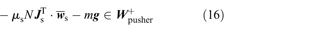
From (17), (18), and (19):

Since the net required wrench lies inside the friction cone of the pusher, the object motion is inside the motion cone.
In the case of uncertainty in the friction at the gripper, to generate robust pushing strategies, we can constrain the planner to the intersection motion cones computed with lower bounds on the friction coefficients and the gasping force. Such a pushing strategy will produce the same regrasp outcome for the expected variation in the friction at the gripper.
8.2.2. Gravity-aligned pusher
In recent work (Chavan-Dafle and Rodriguez, 2018a), we showed that we can generate robust prehensile pushes in the presence of gravitational force by careful selection of pusher contact placement. Specifically, we demonstrated that by aligning the pusher normal along the gravitational force on the object, the dynamics of pushing and the motion cone becomes invariant to all the system parameters except for the friction at the pusher.
Proof. If the pusher is aligned such that the pusher contact normal is along the direction of gravity, the gravitational force on the object is entirely balanced by the part of the normal force at the pusher. Then, for
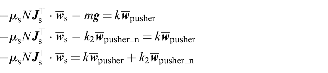
where

where

Now, we can write the dynamics condition for a feasible prehensile pushing with gravity balancing pushers as

Equations (20) and (21) show that the dynamics of pushing, and the consequent motion cone for the gravity-aligned pusher, are invariant to the object mass, grasping force, and the friction coefficient at the fingers.
As discussed in Section 8.1, we can further make the pushing strategies robust to the uncertainty at the pusher contact by planning with lower bounds on the expected coefficient of friction at the pusher.
Figures 17, 18, and 19 show the regrasps in Table 4 planned with the constraint of using only the bottom pusher which is aligned along the direction of gravity.
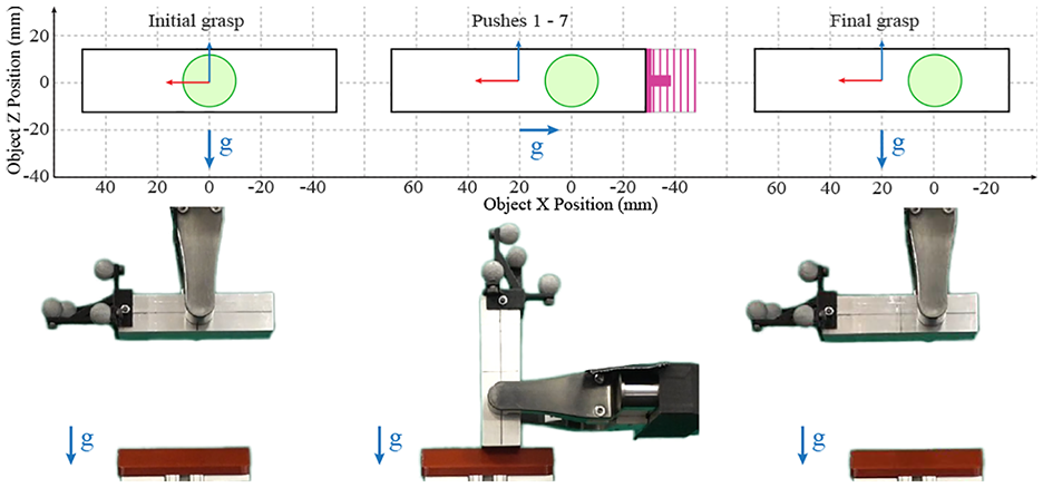
Simulated motion of the object and snapshots of the experimental run for a pushing strategy to offset the object in the grasp using low-coefficient pushers.
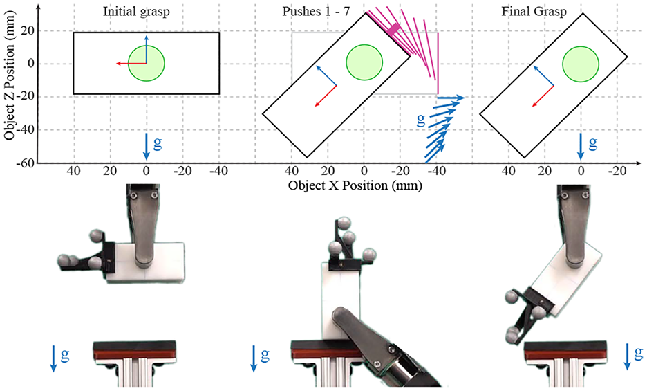
Simulated motion of the object and snapshots of the experimental run for a general regrasp in [
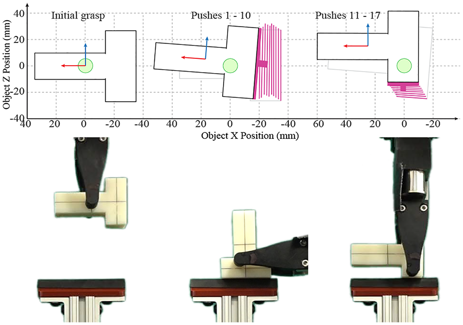
Simulated motion of the object and snapshots of the experimental run for the T-shaped object.
To validate the invariance in the outcome of the regrasp actions planned when the friction at the fingers is changed, we varied the grasping force and executed the same pushing strategy. As the grasping force changes, the friction force at the fingers also change. However, as shown in the plots in Figures 20 and 21, the variation in the outcome of the pushing strategy for the three different grasping forces is negligible. This supports the expected invariance. Moreover, the minimal slip observed at the pusher contacts confirms that the pushing actions selected by the planner result in stable prehensile pushes.
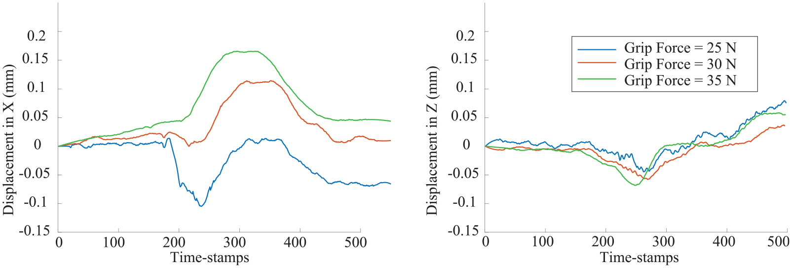
Displacement of the object with respect to the environment for the regrasp action shown in Figure 17. As expected, during pushing, the object sticks to the environment and moves by a negligible amount as the fingers slide on it.
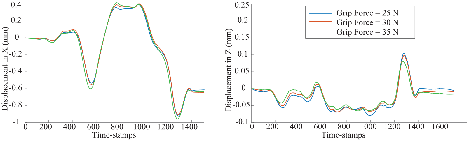
Displacement of the object with respect to the environment for the regrasp action shown in Figure 18.
It should be noted that using conservative friction values at the pusher as proposed in Section 8.1 or modified motion cones as in Section 8.2.1 provides robustness, however, it reduces the volume of the effective motion cones, i.e., the dynamically reachable configuration space. This can adversely affect planning time, especially for problems with “narrow corridors.” The method proposed in this section, however, does not suffer from such an effect since the volume of the motion cones in this case does not change significantly. We observe negligible (fractions of a second) difference in the planning times for the examples considered in this section compared with those in Section 7.
9. Discussion
A motion cone is the maximal set of dynamically feasible velocities that a pusher can transmit to a pushed object. It also describes the set of motions of the pusher that yield sticking contact with the object during the push. It abstracts away the dynamics of frictional pushing and provides direct bounds on the reachable space for pushing tasks.
In this article, we have extended the concept of motion cones to a general set of planar pushing tasks with external forces such as the gravitational force in the plane of motion. We have shown that the motion cone for a general planar push is defined as a cone with low-curvature facets, and have proposed a polyhedral approximation for efficient computation.
We have demonstrated the use of motion cones as the propagation step in a sampling-based planner for in-hand manipulation. Combining a T-RRT*-based high-level planning framework and a motion cone-based dynamics propagation, the planner builds in-hand manipulation strategies with sequences of continuous prehensile pushes in a fraction of a second. Furthermore, we have shown that by constraining the planner to propagate the planning tree through a conservative interior of the motion cones and/or with specific selection of the pusher alignment, we can generate pushing strategies that are robust against uncertainty in the physical parameters of the system.
Throughout this article, we have emphasized the experimental validation of the theoretical contribution and planning framework. Thousands of pushes in different object–grasp–pusher configurations corroborate the analytical computation of motion cones. With a variety of regrasp experiments, we have shown that the pushing strategies generated by our planner result in motions with minimal slip at the pusher contact and negligible variation in the outcome of the regrasp.
The motion cone provides direct knowledge of the set of reachable configurations. It allows us to explore the connectivity of the configuration space for planning through regions/volumes of the configuration space for contact-rich manipulations (Brock and Kavraki, 2001; Morales et al., 2007; Shkolnik and Tedrake, 2011; Shkolnik et al., 2009). Moreover, motion cones, as bounds on pusher actions or as bounds on the object motions, have an adequate form to be incorporated into trajectory optimization frameworks to plan pushing strategies. We believe that the extension and application of motion cones to more general settings provides new opportunities for fast and robust manipulation through contact.
Footnotes
Acknowledgements
This article extends the paper that appeared in the proceedings of the 2018 Robotics: Science and Systems (Chavan-Dafle et al., 2018). We would like to thank the members of the MCube Lab for helpful discussions and advice. Special thanks go to Professor Matthew T. Mason for feedback on the method and suggestions on the graphical illustrations of motion cones.
Funding
The author(s) disclosed receipt of the following financial support for the research, authorship, and/or publication of this article: This work was supported by Mathworks, the MIT Merrill Lynch Fellowship, the NSF Graduate Fellowship, and the MIT–HongKong Alliance.