
Abstract
This manuscript presents an improved control algorithm, called Dynamic Sliding Mode Control based on Multiple Models Switching Laws (DSMC-MMSL), for the control of the depth of the studied Autonomous Underwater Vehicle (AUV) system, the diving plane controller of which faces disturbances arising from the coupled states. The diving plane model is strongly coupled with the state variables, such as surge speeds and course angles. To achieve the desired dynamic performance, the proposed algorithm consists of two parts: the diving plane control part and the pitch control part, which is used to avoid large pitch angles. Some direct switching control laws are used for the two parts to avoid some impulse phenomena on the control executions. The error-states exponential decay is recommended to eliminate the chattering on the sliding surface. The DSMC-MMSL controller was successfully implemented and experimentally validated with the studied AUV system designed and built by Shenyang Institute of Automation. The results of some lake trials demonstrated that the depth control performances of the AUV system were as desired, and that the AUV system was robust enough for the coupled state variables under the DSMC-MMSL algorithm control.
Keywords
Introduction
Depth control is an important issue for Autonomous Underwater Vehicle (AUV) systems during the execution of some tasks. The diving plane mode of an AUV system suffers from high nonlinearity, states coupling and uncertain disturbances [1–4], and several approved control algorithms [5–9] have been suggested and examined for AUV depth control. One popular control technology implemented for underwater vehicles [10], the SMC (Sliding Mode Control) algorithm, is insensitive to external disturbances and robust to parameter variations [11], e.g., an SMC based on a backstepping algorithm is introduced to improve the robustness to external disturbances [14], and fuzzy adaptive controllers pertaining to SMC are used to weaken the scope of chattering on the sliding surface of the SMC [15]. Additionally, some other intelligent control algorithms are introduced. J.H. Li suggested that the diving motion of an AUV should adopt an adaptive nonlinear controller to prevent model errors without considering pitch angles [16]. To address these complex nonlinear questions of AUV systems, some decoupled diving plane models have been introduced to design controllers under various assumptions, such as that the pitch angle should be limited to small values [17], but no method is used to meet this assumption.
This paper focuses on questions regarding the depth control of the studied AUV by investigating the Dynamic Sliding Mode Control based on Multiple Models Switching Laws (DSMC-MMSL) in special lake trials. During the lake trials, we found that the SMC had a better chance of overcoming intricacy questions than the PID control algorithm, which is the initial control algorithm used by the studied AUV. The PID control algorithm was pre-set by engineering specialists with extensive field experience in controlling AUV systems. However, the depth motion is susceptible to coupled states, such as the surge velocity and/or steering angle used for the PID controller. Moreover, the pitch of the studied AUV should not be too large to ensure that other intellectual property venture issues do not occur. Considering these questions, two closed-loop controllers were proposed for controlling the depth and restricting the pitch to the demanded range, using the dynamic sliding mode. Some state-dependent switched control laws are suggested for the two closed-loop controllers. The suggested DSMC-MMSL algorithm, and the control intellectual property parameters which are self-adjusted according to coupled states and disturbances, were considered to settle the aforementioned questions during the lake trials.
Modelling of the Diving Plane Control of the AUV
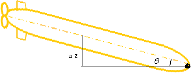
The studied AUV (diagrams are not available because they are the intellectual property of our institution) has a streamlined torpedo-like body and is propelled by a single thruster. For vehicle manoeuvring, two stern planes and two stern rudders on the symmetrically round hull at the rear are used. Two hydroplanes on the rear sides help the AUV to submerge. The diving plane of the studied AUV is sketched in Figure 1.

Body-fixed frame and earth-fixed frame references of the AUV
Considering the manoeuvring structure of the studied AUV system, we assume that the roll and yaw angular velocities are close to zero. Additionally, we decouple the sway motion of the AUV and consider the heave velocity (w) to be small because there is no direct driver to manoeuvre it. Figure 2 shows a block diagram of the studied AUV system for diving plane control with two closed-loop controllers.
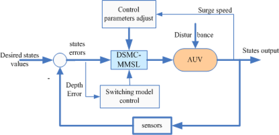
Block diagram of the proposed control system for the AUV dive plane motions
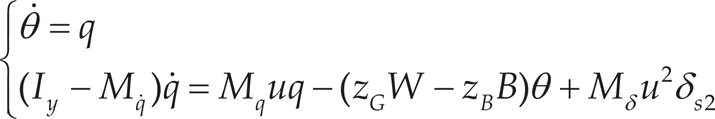
In general, the heave dynamics equation of AUVs can be expressed as: [16]

where u is the forward speed or surge speed, θ is the pitch and w is the heave velocity.
The pitch rate equation can be written as:

where δS (radian) is the angle of the stern.
The pitch kinematics can be described as:

For the studied AUV system, the pitch is restrained θ∊(−15° 15°) and the heave velocity is approximated as w ≈ 0; therefore, sinθ = θ and equation (1) can be simplified to:

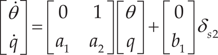
According to the above four equations (1)–(4), the state-space expression for the diving plane model can be described as:

wherea1, a2and b1 correspond to
Here, some symbols of the diving plane model are introduced, and the detailed denotation can be found in a previous paper [14] and a book [26]. The states of the diving plane model are the depth z (metre), pitch θ (radian) and pitch rate q (radian/second). The state of the surge speed u (metre/second) is considered a parameter of the model. The signs of Z*, M* denote the non-dimensional hydrodynamic coefficients of the diving plane model. Iy is the moment of inertia; W and B are the weight and submerged buoyancy force of the AUV, respectively; and h is the distance between the gravity centre and the buoyancy centre along the z-axis of the AUV body-fixed frame.
The pitch angles of the studied AUV system should be kept sufficiently small [19], or the AUV would have a severe accident. The pitch of AUVs should have a method of control [20,21]. According to the physical property of an AUV, the rudder angle cannot be taken as any free value. In other words, the saturated rudder angle is (−25° 25°) viz. [−0.44, 0.44] radian. As for the studied AUV, the pitch angles are limited to (−15° 15°) viz. [−0.26, 0.26] radian to avoid the AUV exhibiting venture events under water. Jan Petrich and Daniel J. Stilwell [22] proposed that a second-order pitch model (6) is sufficient to control the pitch angle. The pitch control model of this paper is written as:
Equation (5) can be described as the state-space expression:
The variables a1 and a2 are defined as in subsection 2.1. The state-space expression (7) represents the pitch control of the studied AUV.
Comparing the state-space expression (5) with expression (7), the states of the diving plane model equation are the pitch rate q, pitch θ and depth z, whereas the states of the pitch control model are only q and θ. Consequently, the dimensions of each expression are distinguished from the three dimensions of the diving plane model and the two dimensions of the pitch control model. As for the different dimensional control model switching laws, P.K.C. Wang [23] introduced some sufficient conditions for a special class of switched dynamic systems with some necessary and/or sufficient conditions using notions of controllability and observability in his doctoral dissertation.
Switching control laws must be designed to maintain a smooth transition from the pitch control model (7) to the diving plane model (5), or vice versa. Switched systems with different dimensions are presented in equation (8). Two controllers are designed according to these two models. Sharp buffeting may be caused at the instant that the two controllers switch; thereafter, the control performances of the relative states will be influenced to wobble, to some extent [27–28]. Wobbling at a constant state is not desirable during the moment of switching [29].

Here, the dimension of the state-space of the diving plane model is different, depending on expression (5) and expression (7) viz. the number of degrees of freedom for each expression. At present, few theories or basic mathematical descriptions exist to support hybrid dynamical systems with state-space dilation and contraction. In this paper, some problems are discussed in order to address this issue with a DSMC-MMSL control algorithm.
Constructing the Sliding Surface for the Diving Plane Model of the A UV System
A Sliding Mode Control (SMC) is the construction process of the sliding surface, and the trajectories of all relative states are forced towards the sliding surface and to stay on it. However, some drawbacks pertaining to the sliding surface may suffer from chattering, which may wear out coupled mechanisms and introduce some undesirable high-frequency dynamics. In this paper, one method was used to deal with the question the theory of state feedback control.
First, the sliding surface was defined as one state-space expression of state-errors. The tracking error vector of the diving plane is described as:
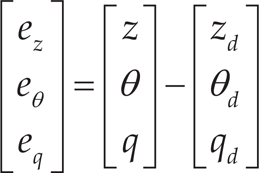
where the states zd, θd and qd are defined as the desired states of depth, pitch and pitch rate, respectively. In general, the desired states of pitch angle and pitch rate are zero; therefore, eθ = θ and eq=q. The state-space expression (5) is represented by the state-errors as follows:

The construct of the sliding surface of the diving plane model is described as:

where c1 and c2 are the parameters of the sliding surface of SMC.
Second, consider the state-space expression (4) used by the state-error and described as:

where
Third, the sliding surface is constructed with a decaying trajectory. The state feedback controller is designed based on equation (12) to achieve asymptotic tracking performance by pre-setting the pole placements of the closed-loop system, whose input variable is the evaluated pitch rate

The pitch rate is pre-set as:
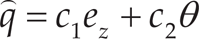
according to equation (11).
The substitution of expression (14) into model (12) and the transmittance of the state-space expression (12) to the transfer function yield:

Therefore, equation (13) and equation (15) are equivalent:

Finally, based on the equivalence shown in equation (16), the relationships between the pre-set eigenvalues and the parameters of the sliding surface are obtained:
Then, the tracking states ez, θand q all asymptotically converge to zero with an exponential decay by pre-setting the eigenvalues of the closed system using equation (13). The tracking error vector will exponentially converge to zero on the boundary layer S, based on the theory of the state feedback control algorithm.

The time derivative of the sliding surface S is

The sliding surface is then considered as one state S instead of state q, and this information is substituted into the state-space expression (10). The state-space expression (10) with a sliding surface can thus be represented as:

Furthermore, the sliding surface should be expressed as:
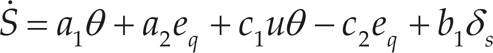
The substitution of the derivative state variable expressions into equation (18) and the rearrangement of equation (20) yields:

The substitution of equation (11) into equation (21) results in:

The control law δs; can then be obtained:

The additive term can be neglected as the sliding surface exponential decays to zero, and equation (23) can also be presented as:

Equation (23) can be proven by the Lyapunov stability theory:
The series of pitch error equations based on the diving plane model can then be constructed without considering the state depth ez:

where δs2 is the input variable of the pitch model, i.e., equation (25).
Neglecting the state depth ez while designing the sliding surface and deducing the pitch closed-loop control law δs2 results in:

The closed loop of pitch control is used to ensure that the output for the pitch angle is found within the limited range.
It can be observed from the two control laws that the pitch control law δs2 originates from the diving plane control law δs by removing the state depth ez. Equation (27) portrays the relationship between these two aforementioned closed-loop control laws, i.e., equation (24) and equation (26). The chattering phenomenon would not be neglected if the two control laws switched with each other directly. Some switching control laws should be used to make the transition between these two controllers smooth.

A state-dependent switching control law is suggested with respect to the two foregoing control laws of the studied AUV. The diving plane is controlled by two translational rudders placed symmetrically on two sides of the after-body of the studied AUV. The placement of the control execution framework makes the state depth control entirely reliant on the pitch. The range of the pitch angles should not fall outside the range [−0.26, 0.26] radian, or some venture issues would occur.
Some switching control laws should be used to make the transition between these two controllers smooth. In other words, switched systems of the diving plane are described as shown in equation (27), corresponding to the switching control laws for the transition between these two controllers. A state-dependent switching control law is suggested. The diving plane control of the AUV system is executed by two translational rudders placed on two sides of the after-body of the AUV. The placement of the control execution framework makes the depth entirely reliant on the pitch angle.
The state-dependent switching control law is designed according to:

The switching control law results in switched systems with different dimensional state-space expressions. A switched system is stable if all subsystems are stable and the dwell time is sufficiently large. In general, a switched system is presented as:

where Σ is the switching control law.

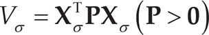
Considering

where Vj(
If the condition shown in equation (30) can be satisfied, then the switching control is stable. The proof of this theorem was detailed by Daniel Liberzon in his book [30] with multiple Lyapunov functions, and is thus not included in this paper.
The switching control law described in this paper considers not only state-dependent but also dimension-variable state-spaces of switched subsystems. Decreases or increases of the state variable result in an impulse effect during the switching, and the system passes through a switching surface. The following paragraphs introduce some deductions that can be used to solve this impulse effect.
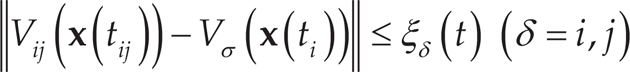
where Vij(
The following energy function for the running controller δi can be constructed:
The differential equation of the Lyapunov function (33) satisfies the stability theory because if every subsystem is stable under its corresponding control law for δΣ, then VΣ <0 and VΣ<∊(t), where ∊(t) is a positive function. If the Lyapunov function of the switching process meets the condition
Every subsystem is stable under its corresponding controller; thus, the function of Lyapunov is continuous, and the inequality
Therefore, the switching process is stable with increasing or reducing state variables, according to the Lyapunov theory.
The switching control law for diving plane control of the AUV is designed according to

The desired curves of the energy values and rudder angles

is satisfied, then the switched system (8) is stable under the direct switching law.
The energy function for every subsystem
The following switched systems of the studied AUV can be considered:

Using equation (34), we can determine whether the state depth is abolished. The state-dependent equation is considered to be the switching control law (28), which changes the equation for the switched controllers to

According to
To verify the validity of the proposed algorithm for AUV depth control, several lake field trials were performed. All trials focused on the performance of the diving plane, such as the stability, dynamic performances and robustness to disturbances with suddenly changing coupled states.
Control Characteristics of the Diving Plane States Under DSMC-MMSL
The performance of the diving plane model for the studied AUV system was tested using DSMC-MMSL in several lake trials.
The first lake trial was used to validate the model's stability and ensure its dynamic performance by executing tasks at the demanded depth of 8 metres underwater. The results (Figure 4) show that the studied AUV system is stable under the pre-set excitation conditions in the diving plane.

Results of the depth control with a constant desired depth by DSMC-MMSL
The stability, the small static error (0.02 m) and the settling time (60 seconds) indicate that the steady-state performances are favourable. Additionally, the depth curve shows that the dynamic performance meets the performance indexes for a small overshoot and short settling time. Moreover, Figure 4 shows that DSMC-MMSL efficiently attenuates the undesired chattering on the sliding surface because the output of the stern plane deflection angle does not exhibit the undesired frequent chattering.
The second lake trial was performed to determine whether the DSMC could meet the required control performances by only considering the three-dimensional diving plane control law equation (24), without considering the pitch control law. The trial demanded that the depth be 8 metres underwater. The results (Figure 5) show that the overshoot is 37.5%, which is an unexpected transient response; meanwhile, the maximum pitch angle is more than 30 degrees, which is greater than the limited pitch angle, and the horizontal rudders were within the saturated range for a long time, which is undesired. All of these phenomena show that the advised algorithm could not meet the control performances if the pitch control law was not considered. The reason for the large overshoot in the depth is the large pitch angles of the AUV system during submergence underwater. The depth gauge is installed on the head of the AUV, which accounts for the large pitch overshoot. One variable is the vertical distance between the centre of the AUV body and the location of the depth gauge, when some pitch angles exist.

Results of DSMC with only depth closed-loop control
To overcome the problems found in the second trial, DSMC-MMSL was applied during the third trial using the same task as in the second trial. The results of this field trial (Figure 7) show that the overshoot is 9.2%, and that the largest pitch angle was only 11.33° during the transitional process of the depth response. Compared to the results of the second field trial, the dynamic performances were efficiently improved by the depth closed-loop control with pitch closed-loop control.
Another lake trial was performed to validate the stability of the switching law between the control laws, i.e., equation (24) and equation (26). The premise of the trial was as follows: the first desired depth was 5 metres for 1100 seconds, at which point, the depth was supposed to increase to 11 metres. The switching laws would be used at the instant of the depth transition. The results of this trial are described in Figure 8, and the transition of the switching control law is denoted by the arrowhead in the figure. The pitch control law, i.e., equation (26), was used as soon as the error in the depth was less than 4 metres, otherwise, the control law, i.e., equation (24), was used. The results of the trial on the switching control demonstrated that the aforementioned switching control laws could maintain stability of the switched system (8) at the moment of switching. Moreover, the results show that there is no sudden, sharp chattering at the moment of transition from one controller to the other.
Sketch of the overshoot by a large pitch angle

Results of the diving plane control with DSMC-MMSL
Initially, the PID (Proportional-Integral-Derivative) control algorithm was used to control the diving plane motions of the studied AUV, but several drawbacks, such as a large overshoot and suffering from disturbances originating from some coupled states, emerged. The abilities of a classical PID algorithm could not meet the goals of good control performance when the orientation angles or the surge speeds changed suddenly. Moreover, the control parameters of PID had to be adjusted according to different tasks in order to obtain adequate control performances.

Dive plane control with switching control
Figure 9 shows the results of one lake trial at the desired depth of 8 metres underwater using a PID controller for the studied AUV system. The depth values were continually changed by sudden changes in the surge speeds or course angles. As shown by the denoted lines, the depth of the studied AUV system could not remain stable when the surge speeds or orientation angles suddenly changed.

Results of the diving control system in response to sudden changes in the orientation angles
To compare the PID control algorithm with the DSMC-MMSL algorithm, some lake trials were performed to prove that the DSMC-MMSL algorithm was robust to changes in the coupled states. The results of these lake trials are shown in Figure 10 (the desired depth was 15 metres underwater). One lake trial was performed with sudden changes in the course angles, and the results show that the depth was not influenced by changes in the course angles. Moreover, the lake trial included the execution of diving plane control in response to sudden changes in the surge speeds, and the results (Figure 10) show that the AUV system is robust to disturbances caused by changes in the surge speed. The trial validates the theory that the proposed control algorithm can overcome the influence of the coupled states.
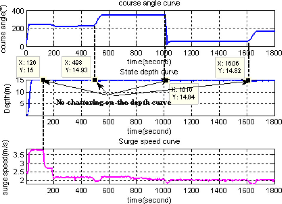
Results of the diving control system in response to sudden changes in the orientation angles and surge speeds
A control algorithm, namely a dynamic sliding mode control with a multi-model switching control, was proposed to control the depth of the studied AUV. Compared with the initial controller (PID controller), the depth controller was robust to the disturbances caused by changes in the coupled states, such as surge speed and course angle. This was because the DSMC-MMSL has the capability to self-adjust its control parameters in response to changes of the surge speed. Moreover, the proposed algorithm can maintain the pitch angle within strict limits because the pitch closed-loop control method is used with the depth closed-loop controller. Compared to the PID control algorithm, which has been used and continually improved over many years due to new demands, the DSMC-MMSL algorithm primarily solves some deficiencies that were mentioned in section 4.2. All of these aforementioned advantages of the DSMC-MMSC algorithm were validated by multiple lake trials.
Footnotes
6.
This paper is supported by the National Natural Science Foundation of China (Grant No. 51409047, 61273334), the State Key Laboratory of Robotics (2012–008) and the Education of Jiangxi Province (GJJ13466).