
Abstract
A four-wheel independent steering (4WIS) and a four-wheel independent driving (4WID) agricultural data acquisition vehicle (ADAV) system was designed to monitor and manage the growing status of bio-energy crops. To avoid destroying crops, a changeable wheel gauge and high-clearance design was employed, which brought new problems to the ADAV system: reduced path-following precision and driving stability. Given the dynamic characteristics of the ADAV system, an additional yaw moment control (AYC) system was designed to achieve high path-following precision and stability of the ADAV system. Using the input steering wheel angle and driving speed, the desired yaw rate and sideslip angle were calculated. The difference between the desired and actual yaw rate and that between the desired and actual sideslip angle were employed as feedbacks to obtain an additional yaw moment executed on the ADAV system in real time. The effectiveness of the AYC system was verified in field tests. Experimental results show that the actual yaw rate, sideslip angle and path trajectory were close to the desired ones. Therefore, the stability and path-following accuracy of the ADAV system were improved.
Introduction
Agricultural data acquisition vehicles (ADAVs) for the close-proximity monitoring of crops have been proven to be an effective means for precision agricultural applications. An ADAV system is a mobile crop monitor as well as a data collector which can run in off-road environments by following a desired path. Similar machines have been proposed in the past few years. The Agricultural Robotics Laboratory at Iowa State University (Ames, Iowa, USA) modelled a four-wheel steering (4WS) and four-wheel driving (4WD) small agricultural robotic platform and assessed its dynamic behaviour and stability through simulation [1]. Agricultural machinery for weed control and crop monitoring has been studied world-wide. An autonomous plant-care instrumentation (API) system was introduced by Tommy Ertbølle Madsen and Morten Bisgaard et al. in Denmark [2, 3] which was equipped with a 4WS and 4WD locomotion mechanism. Bjorn Astrand et al, from Halmstad University, Sweden, introduced their vision-based agricultural mobile robot for mechanical weed control [4]. An autonomous robot for weed control was designed by Tijmen Bakker at Wageningen University (Wageningen, The Netherlands) [5]. A six-wheeled omnidirectional autonomous mobile robot using a multiresolution behaviour-generation strategy was developed by Utah State University [6].
However, unstructured roads or rough soil surfaces create huge challenges for applications of ADAV systems. It is important for an ADAV system to follow the desired path with the desired speed so that it can monitor crops at the right location without destroying them. Therefore, many researchers have investigated path-following approaches for agricultural vehicles. Anthony Stentz et al. [7] designed a path tracker to achieve accurate path tracking. The tracker used a modified form of the pure pursuit algorithm (PPA) [8] based on a simple kinematic model. In another study, a model predictive control method (MPCM) was applied in order to preserve the accuracy of the path tracking in the presence of sliding based on an extended kinematic model [9]. However, these two studies did not take vehicle dynamics into account. As the vehicle speed increases, the vehicle dynamics play a significant role and the error of these algorithms increases. A method was employed whereby longitudinal and lateral control was combined to avoid obstacles [10]. Yang et al. [11] introduced a tracking controller for a mobile robot by integrating the neural dynamics model into a conventional feedback controller. Wit et al. [12] utilized a path-tracking technique called “vector pursuit”. This technique was based on the theory of screws. It generated a desired vehicle-turning radius based on the vehicle's current position and orientation relative to the position of a point ahead on the planned path and the desired orientation along the path at that point. Hiraoka et al. [13] proposed a path-tracking controller for a 4WS vehicle based on the sliding mode control theory which exhibited good path-tracking capability and robustness against cornering-power perturbations. Several papers designed lateral control systems for path tracking; for example, Byrne et al. [14] designed a model reference adaptive controller for vehicle path tracking. It was able to guarantee both stability and performance over a wide range of slowly varying parameter changes as long as several conditions were met. The authors used the Takagi–Sugeno (T–S) fuzzy model of vehicles obtained from a nonlinear model and designed a fuzzy controller to control path following for vehicles [15]. Moriwaki [16] introduced an H8 optimal controller so that the vehicle could follow the reference path. Bakker [5] designed a path-following control system for a robotic platform. The deviation of the robot from the desired path was supplied to two high-level controllers, which minimized the orthogonal distance and orientation to the path.
In this paper, a four-wheel independent steering (4WIS) and a four-wheel independent driving (4WID) ADAV system was developed to monitor and manage the growing status of miscanthus, the most enthusiastically promoted renewable energy crop in the European Union and North America [17, 18]. The ADAV platform design and system architecture are presented in Section 2. In Section 2, a changeable wheel gauge and high clearance design was employed to avoid damaging the crops. To improve the path-following capability and driving stability, an ADAV system dynamics model and an additional yaw control (AYC) system are proposed in Section 3. The effectiveness of the AYC system is verified in the ADAV system through field tests in Section 4. We concluded that the accuracy of the path following and driving stability of the ADAV system were improved by the AYC system.
ADAV System Design
Reliability of agricultural vehicles is a very important issue, especially for heavy machines working in the field. To fulfil the requirements of off-road environments and highly accurate agricultural operations, a 4WID and 4WIS design was employed. Furthermore, the ADAV system used a changeable wheel gauge and a high-clearance design so that it could drive through plant plots without destroying crops. The ADAV system was operated manually through a remote ground station or else controlled by an on-board vehicle controller.
Vehicle Platform Design
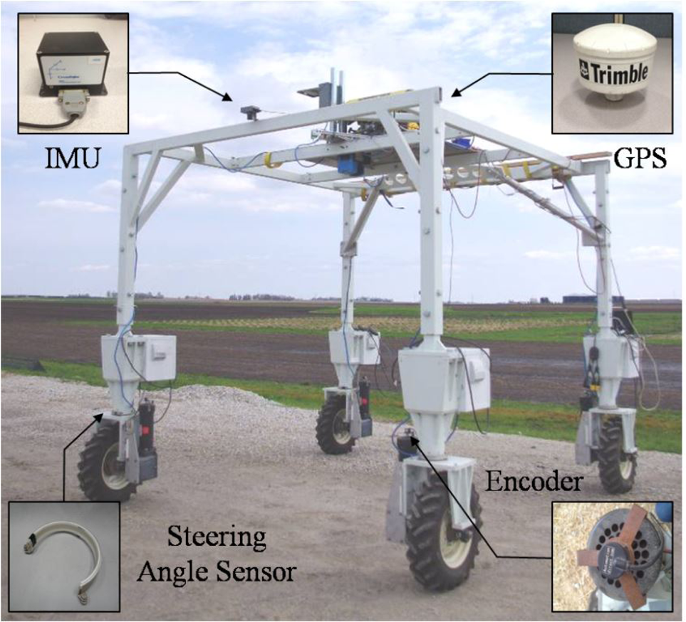
The ADAV system is a mobile crop monitor and data collection platform originally developed for the close-proximity monitoring of miscanthus, an energy crop which can grow up to 3-4 m high. The ADAV system was designed to be 3 m long, 3 m wide and 3 m high, and could be lifted manually up to 4 m high when used to measure mature miscanthus, as shown in Figure 1. A 4WID and 4WIS design was employed to enhance the reliability of the ADAV. Each leg-like module included a DC motor for driving and a high-torque stepper motor for steering. Furthermore, there were clutches in both the driving and the steering systems in case the wheels ceased to work. If this happened, the ADAV system was able to drive out of the field by taking working wheels as driving wheels and taking broken ones as driven wheels, therefore causing less damage than would be the case with the use of other transportation machines.
The total driving power of the ADAV system was about 3 kW. It was designed to move at 2 m/s in a working field and 5 m/s on a flat surface. A 6.5 kW heavy duty gasoline generator was equipped on the top of the ADAV system which powered the four leg-like modules (driving motors and steering motors) and monitoring sensors. The system is able to continue monitoring and data collecting for eight consecutive hours.
Miscanthus is usually planted in rows with a fixed inter-row distance (762 mm in our experiment). With this distance, the ADAV system was designed to monitor four rows at the same time. However, planting errors usually occur and miscanthus is likely to expand to occupy the inter-row space, especially during maturing seasons. Therefore, the ADAV system used a changeable wheel-gauge design to avoid damaging crops. There is an offset d (about 0.07 m, 10% of the inter-row distance) on each wheel, and the changeable wheel-gauges were attained by changing the wheel direction, which is easily adjusted in the four leg-like modules. Defining the leg distance along the lateral axis as L, Figure 2(a), each different possible wheel-direction arrangement produces different a wheel-gauge distance. Keeping the left wheel straight and forwards, and turning the right wheel 180 degrees, will make the wheel gauge change from L to L−2d, as shown in Figure 2(b). When only the left wheel is rotated 180 degrees, the gauge is adjusted to L +2d as shown in Figure 2(c). The fourth layout (d) is the opposite of layout (a) and shares the same gauge value. Furthermore, when the ADAV has to drive into extreme-density plots, each leg-like module will be equipped with a cuneal cover to separate the crop rows.
The ADAV system and sensors
However, this high-clearance and changeable wheel-gauge structure brings new problems: an increase of steering-resistant torque, an increase in the nonlinear characteristics of the control system, and a reduction in the path-following precision and system stability. On the one hand, the steering operation becomes difficult because the driving force on each wheel produces a steering-resistant torque on the steering axis due to the wheel offset d. In fields, when the ADAV system is run on an extremely rough road with turns, the steering motor may not provide sufficient steering torque and may result in under-steering and path deviation. On the other hand, when the ADAV system takes a sharp turn at high speed, it becomes unstable and difficult to operate due to its high clearance. To solve these problems, an AYC system was applied to improve its path-following capability and driving stability by adjusting the driving force of each wheel.

Different layouts of wheel gauges (not to scale)
The ADAV system is manually operated through a ground station which includes a steering wheel and a feedback display laptop. The ground station, the on-board vehicle controller and the four leg controllers communicate using wireless technology through on-board WiFi, as shown in Figure 3. All the system status information, including the desired and actual sideslip angle, yaw rate, driving motor speed, steering motor speed and steering angle, are displayed on the ground station laptop to help operate the system. An operating software interface was developed using Labview (National Instruments, Austin, TX, USA), as shown in Figure 4.

Overview of the control system of the ADAV system
The on-board vehicle controller, an ARM single-board computer (ST-7800, Technologic Systems, Fountain Hills, AZ, USA), is the master in the ADAV system, which takes charge of the vehicle motion control. An ADAV system dynamic model based on an AYC algorithm was programmed on the vehicle controller. The on-board vehicle controller is also responsible for operating the monitoring sensors on the vehicle and communicates with the ground station, allowing the remote control of the vehicle.

ADAV system control interface
Each leg-like module is a directly digital control (DDC) module with a controller, actuators (drivers and motors) and feedback sensors. For each wheel, an independent single-board computer (BL5S220, Rabbit, Minnetonka, Minnesota, USA) was selected as the leg controller for real-time driving force and steering-angle management. A driving motor driver (TDP502, Trooper, Heath Springs, SC, USA) and a DC motor (4Z378, Dayton, OH, USA) were equipped to obtain driving force control, while a steering motor driver (KL-11078, Keling Tech, Hoffman Estates, IL, USA) and a stepper motor (KL42H2150, Keling Tech, Hoffman Estates, IL, USA) were employed to provide steering control. To get feedback signals, a 2,500 pulse/rev optical encoder (TRD-S2500BD, Automation Direct, Cumming, GA, USA) was mounted at the rear of each driving motor to measure motor speed, while a potential meter was customized to measure the steering angle, as shown in Figure 1.
In most cases, the surface of working fields is rough and bumpy. The working speed of the ADAV system is about 2 m/s. If the ADAV system is run on an extremely rough surface, the steering motors may not be able to provide sufficient steering torques, which may result in under-steering and path deviation when turning. On the other hand, when the ADAV system is run from a working field to a workshop, the field surface would be much flatter so that the running speed is usually about 5 m/s. In this situation, when the ADAV system suddenly turns to avoid obstacles or takes a sharp turn, and due to the ADAV system's high-clearance design, it becomes unstable and difficult to operate. An AYC system was designed to achieve high path-following accuracy and stability of the ADAV system using insights into the dynamic characteristics of the system.
ADAV Dynamic Model
To improve the path-following capability and driving stability, the steering and lateral stability of the ADAV system need to be enhanced. It is assumed that the ADAV system runs at a constant speed and only has two degrees of freedom (2-DOF), lateral translation motion and yaw rotation. The vehicle sideslip angle β and yaw rate r are state variables. The input, front- and rear-axle steering angles δf and δr can be calculated from corresponding the wheel-steering angle. When the lateral acceleration is smaller than 0.4 g, the tire model is linear [17]. The wheel offset d mentioned in Section 2 is about 0.07 m, which is much smaller than the wheel gauge L (3 m), and so that is ignored in the dynamic model. Figure 5 illustrates the 2-DOF dynamic model considered herein.
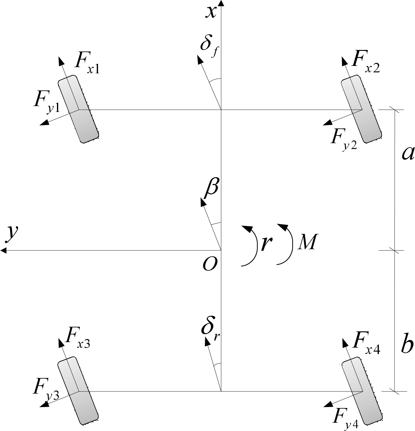
DOF dynamic model of the 4WIS-4WID ADAV system
The front- and rear-axle sideslip angles αf and αr are described as follows:


The equation of the linear tire model is:


The motion equation of m the vehicle is as follows [19]:

The parameter meanings are listed in Table 1.
Definitions of parameters.

The control strategy of the 4WIS+4WID+AYC system is shown in Figure 6. According to input steering wheel angle and driving speed, the ideal model is used to obtain the ideal sideslip angle βd and yaw rate rd. Details of the ideal model are described in equation (13). Next, the ideal sideslip angle and yaw rate are compared with the actual ones in the feedback controller to obtain the additional yaw moment, ΔM.

The block diagram of the 4WIS+4 WID+AYC system The state equation of the vehicle motion is:

where,
Generally, the ideal state occurs when the steady-state yaw rate equals that of the front-wheel steering model. After performing a Laplace transform on the state equation, β(s) and r(s) are obtained as:


In the steady-state condition, let

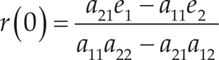
Then,
The ideal transfer function of the state variables is [20]:

where,
The subscript d represents the ideal value, while kr and

where,
The difference between the ideal value and the actual value e is e = X-Xd, such that:

The last two parts are caused by external interference. Let

Then,
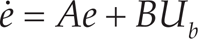
The error e can be compensated by a feedback-controlled value Ub. Let Ub=-Ke, where K is the feedback matrix. K=[k1k2].
The performance value J is [21]:

The feedback factors k1 and k2 are obtained using the minimum value of J. qb1, qb2 and rb are weight coefficients, which are determined according to the state variables and input control signals.
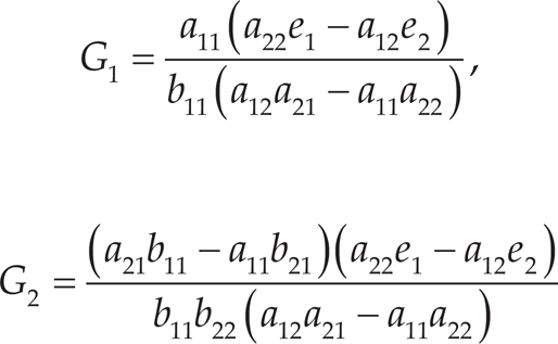
Rewrite equation (14) as:

where,
The feedback factors k1 and k2 can be calculated using an LQR algorithm. By adjusting the driving-motor output torque, driving force is produced on each wheel. Next, the additional yaw moment is obtained by adjusting the driving force of one specific wheel. To simplify the control strategy, we only adjusted the driving force of the left-rear or right-front wheel. For example, if the yaw rate is counterclockwise and smaller than the ideal yaw rate, the driving torque of the left-rear wheel is reduced to obtain an additional counterclockwise yaw moment. If the yaw rate is counterclockwise and greater than the ideal one, the driving torque of the right-front wheel is reduced to obtain an additional clockwise yaw moment. In the same way, the control strategy can be summarized when the yaw rate is clockwise.
The capabilities of the proposed 4WIS+4WID+AYC system were examined on the ADAV system via field tests. The ADAV system is equipped with a three-axis accelerometer/rate gyro (DMU-HDX, Crossbow, Milpitas, California, USA) sampled at 30 Hz. The sensor noise levels (1s) are 0.06 m/s2 for the accelerometers and 0.2 deg./s for the rate gyros. The ADAV system is also equipped with Novatel GPS antenna/receiver pairs providing 5 Hz velocity measurements and 1 Hz attitude measurements with a noise level (1s) of less than 3 cm/s and 0.2 deg. respectively. In addition, there are four wheel-speed and steering-angle sensors on board. The values of all of these sensors are sent to the on-board vehicle controller.
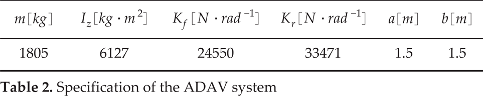
The parameters of the ADAV system are listed in Table 2.
Specification of the ADAV system
Specification of the ADAV system
There is no regular law for choosing the values of Q and R, and it usually relies on the designer's experience. Several different values are tested to choose the most effective one based on the experimental results. In the following experiments, we set
In the step-input and sine-input tests, the driving stability of the ADAV system was examined. The ADAV system was run on a flat meadow at a constant speed of 5 m/s (18 km/h). For the step-input test, the steering wheel angle input was changed from 0 to 120 deg. (≍2.09 rad, gear ratio = 15) in 0.5 s. The input of the steering wheel angle and the resulting yaw rate and sideslip angle are shown in Figure 7.
Without the AYC, the response of the yaw rate oscillates at the beginning and converges at about 2 s to a stable value. The maximum deviation between the yaw rate without control and the desired one was about 0.05 rad/s, which resulted in the unstable state of the ADAV system. In addition, the time lag of the yaw rate caused the slow response of the ADAV system, which made it difficult to operate. In contrast, the response of the yaw rate with the AYC was closer to the desired response. There was no oscillation and the stable error, about 0.005 rad/s, is acceptable. The near-ideal yaw rate response makes the ADAV system easier to operate.

Response of the yaw rate and sideslip angle to the step input
Furthermore, the performance of the sideslip angle was improved. The desired sideslip is zero - which is the control goal - making the ADAV system more stable. The sideslip angle with the AYC increased to a stable value without an oscillation within 1 s. The stable value was about −0.01 rad, which was small enough. Similar to the yaw rate without control, the sideslip angle without control oscillated for about 2 s and then converged to a stable value of −0.03 rad. The greater the absolute value of the sideslip angle, the more unstable the ADAV system.
Figure 8 shows the experimental results with a sinusoidal steering wheel angle input when the ADAV system was run on a flat meadow at a speed of 5 m/s. The input amplitude was 150 deg. (≍2.62 rad, gear ratio = 15) with a period of 3 s.

Response of the yaw rate and sideslip angle to the sinusoidal input
In Figure 8(b), by applying AYC, the yaw rate was successfully controlled to the desired value. The error increased as the steering angle increased, but the maximum error, about 0.2 rad/s, was acceptable. Furthermore, the response speed was mainly synchronous with the desired one. However, the response speed of the yaw rate without control was delayed for about 1 s during the first period, and more as time went on. Due to the high vehicle-speed and rapid change of the steering wheel angle, the ADAV system without control lost its stability and was unable to follow the sinusoidal path.
The sideslip angle was also guaranteed to be limited with the AYC system. Its response speed was similar to that of the steering angle and the maximum value was limited to 0.08 rad. On the other hand, the sideslip angle without control had a maximum error of 0.17 rad - and was delayed longer as time went by - and it failed to respond to the sinusoidal input, as shown in Figure 8 (c).
In this test, the path-following ability was verified. The ADAV system was run on a rough field at 2 m/s (7.2 km/h) which was full of bumps and hollows. The steering wheel angle input was changed from 0 to 300 deg. (≍5.24 rad, gear ratio = 15) in 0.5 s. Figure 9(a) illustrates the steering wheel input curve. The resulting yaw rate, sideslip angle and path trajectory are shown in Figure 9(b-d).

Response of the yaw rate, sideslip angle and path trajectory to the trapezoid input
As previously mentioned, when the field surface is full of bumps and hollows, the steering motors cannot offer enough steering torque. Therefore, under-steering of the ADAV system occurred, which caused a deviation of the desired path trajectory. Figure 9(b) shows the response results of the yaw rate. Without the AYC, the yaw rate was smaller than that desired from the beginning and increased due to the continuous steering torque. The response delay was small at the beginning. However, when the steering wheel angle returned to zero, the yaw rate without control was still great and only just began to converge to zero with a time delay of about 1.5 s. At the end of the experiment, the total time delay was about 3 s. On the other hand, the yaw rate with the AYC nearly had no delay and the steady yaw rate value was close to that desired. The maximum error was about 0.005 rad/s. As for the sideslip angle, it was similar to the yaw rate response result, and as such it is not explained here.
Figure 9(d) shows the path trajectory of the ADAV system. The desired path-trajectory is made of two semi-circles with a radius of 17 m. The ADAV system with AYC followed the desired trajectory well with a maximum deviation of 0.1 m. However, the path without control clearly shows under-steering characteristics. During the first semi-circle manoeuvre, the greatest deviation regarding the desired path trajectory was about 3.5 m. When the steering wheel angle returned to zero, the ADAV system without control did not reach point (34, 0). It was still about 7 m from this point, and the ADAV system started to respond to the second semi-circle manoeuvre. As a result, the path of the second semi-circle manoeuvre was above the desired one. The accumulated error became greater later on; furthermore, the greatest deviation was reached at the end of the path - about 5.4 m. In these circumstances, the ADAV system would eventually run onto the crops and destroy them.
This study presents an AYC system that enables high path-following accuracy and stability for an ADAV system. The vehicle dynamics characteristics were taken into account to decrease the algorithm's error. Besides path-following capability, the driving stability of the ADAV system was evaluated. Therefore, both the yaw rate and the sideslip angle were chosen as state variables to improve the control accuracy. The vehicle model is simplified as a 2-DOF linear model and so the LQR method was employed to obtain optimum control. Finally, an additional yaw control (AYC) system was executed by adjusting the driving force of specific wheels. Based on several experiments, it was determined that, when the ADAV system was running at high speed, it was unstable without the AYC system. For the step-input manoeuvre, the yaw rate and sideslip angle without control oscillated at the beginning and no stable conditions were attained. For the sine-input manoeuvre, due to the frequent change of the steering wheel angle in a short time, the response of the yaw rate and sideslip angle without control were delayed and could not converge, indicating the instability of the ADAV system. On the other hand, the responses of the yaw rate and sideslip angle with the AYC were closer to the desired ones. The deviations were acceptable. When the ADAV system was operated at low speed, the yaw rate and sideslip angle without control were smaller than the desired ones, which caused under-steering and path deviation. After applying the AYC system, the yaw rate and sideslip angle were much closer to the desired ones, with almost no delay, and the maximum path-deviation was only 0.1 m. According to the results, the performance with the AYC exhibited better path-following accuracy and driving stability than the performance without the AYC. Furthermore, the results with control were acceptable for the ADAV system and comparable with related research. The improvement of accurate path-following capability and driving stability provides a basis for the autonomous control of the ADAV system in future work.
Acknowledgements
The authors would like to thank the Energy Biosciences Institute (EBI), University of Illinois at Urbana-Champaign, for supporting the programme “Engineering Solutions for Biomass Feedstock Production: Pre-harvest Crop Monitoring System”. The present research work is the part of this programme, and we would like to express our gratitude to the investigators and administrative support staff.