
Abstract
In this paper, a multi-focus image fusion method based on Dual-Tree Compactly Supported Shearlet Transform (DT CSST) and Direction Decision Map (DDM) is proposed. DT CSST is a shift invariant modification of conventional Compactly Supported Shearlet Transform (CSST). Based on the mitigation of shift variance of CSST in DT CSST, a clearer fused image could be acquired through the General Image Fusion (GIF) method, and this image is called the initial fused image in this paper. The decision map is determined by the similarity of the initial fused image and the source images. The generation algorithm of the decision map in this paper takes advantage of the directional nature of DT CSST: every direction of the transform generates an initial directional decision map and then yields the final map through vote and smooth steps. This scheme is called DDM in this paper. The proposed method is evaluated by four groups of standard images. The results show that the proposed method is able to improve the quality indices compared with two algorithms which have excellent quality indices.
Keywords
Introduction
Image fusion is a long-studied field that is attracting ever-increasing attention for a number of applications, such as remote sensing, navigation for robots, etc. Multi-focus image fusion, a branch of image fusion, refers to the fusing of two or more source images with various focus distances into an “all-in-focus” image. The fused images will substitute vague objects or areas with clearer ones. There are two types of image fusion method. The first type is performed directly in the spatial domain, such as using the pixel of the fused image as the average, large or small value of the input images. The method of this type is simple and easy to implement, but its quality is relatively low. The second type is performed in a certain Multi-Scale Transform (MST) domain, and it is called General Image Fusion (GIF) in this paper. Although the method of this type is relatively more complex and has a larger computation complexity, it usually results in better visual perceptions and quality indices. Many MSTs are introduced into these methods, such as Discrete Wavelet Transform (DWT) [1–5], Curvelet [6, 7], Band Limited Shearlet [8] and Compactly Supported Shearlet Transform (CSST) [9, 10], etc.
Shearlet has emerged in recent years as among the most successful frameworks for the efficient representation of multidimensional data. Indeed, many other transforms are introduced to overcome the limitation of traditional MST's poor ability in capturing edges or other anisotropic features. Shearlet transform stands out since it has many unique advantages: a single or finite set of generating functions; optimally sparse representations for multidimensional data; unified treatment of the continuum and digital realms; and compactly supported transform. In this paper, the CSST is selected as the MST for image fusion, because 1) it is easy to implement, 2) its computation cost is comparable to DWT, 3) it is compactly supported in the spatial domain, which is in accordance with the features of natural images such as edge, texture, etc., which are also compactly supported in the spatial domain. However, conventional CSST is shift-variant and will cause the presence of artefacts in fused images. The mitigation of its shift-variant property is necessary.

Forward and backward transform of CSST
In [11], Li proposed a spatial fusion method called Local Fraction Dimensions with Decision Map. Its quality indices are lower than those of frequency-based methods. In [12], Li et al. proposed a multi-focus image fusion method with an additional post-processing step, called the detection of the focused region, after GIF is performed. The idea of the post-processing step is to determine the similarity between the initial fused image and both source images based on the Root Mean Square Error (RMSE). The similarity is recorded by a decision map, and the final fused image is the weighted sum of the clearer areas of the source images and the initial fused image. This method is motivated by the fusion of noise images, while the scheme can also improve the quality of clear images. In another paper [13], Li et al. gave more details about how to calculate the decision map from both regional RMSE and Correlation Coefficient (CC), and a dual-window technique is performed to calculate the final fused images. Both methods are successful because the fused images have good perceptions and the quality indices are higher than many methods. However, they can still be improved. Firstly, both methods are based on wavelet transform, which lacks the ability for geometric analysis. Secondly, the decision map is based on RMSE, and it has been verified that RMSE cannot reflect the quality of different images according to the visual effect [14], and on the regional CC, which will cause the denominator to be zero if the local pixels equal each other. In this paper, the scheme of Directional Decision Maps (DDM) is proposed, whereby the initial decision maps are generated in each direction of the CSST. DDM can take the advantage of CSST's geometric analysis ability. In addition, the local Q values [14], instead of RMSE or CC, are selected in generating each decision map to overcome the invalidation of regional CC. The experiments based on several standard images are used to evaluate the visual perceptions and quality indices of the proposed method and methods in [12] and [13].
Conventional CSST, first proposed by Lim in [15], describes the spatial domain implementation of a cone-adapted shearlet transform. CSST has also proved to be almost optimally sparse for cartoon-like images [16, 17].
As this paper is not a thorough introduction to the theory of CSST, only the steps are briefly given in Figure 1. The left parts are the steps of the forward transform and the right parts are the steps of the backward transform. Both forward and backward transform have two steps: Shear and Anisotropic Discrete Wavelet Transform (ADWT), but in the reverse order. As shown in Figure 2, the shear step can elongate source images along the horizontal directions by different selected k, as well as in the vertical directions. ADWT can also further generate the coefficients at different scales (j) and positions (m). The coefficients at different scales, directions and positions in the horizontal and vertical cones are represented by
In order to mitigate the shift invariance of Conventional CSST, ADWT is substituted by dual-tree complex wavelet transform (DT CWT) in [18], and the mitigation of the shift variance of transforms can improve the image fusion performance in other transforms too, such as DT CWT [5], curvelet [7], etc.

Shear in horizontal direction
The research on constructing the General Image Fusion method can be said to originate in the prestigious work of Pella in [19], where the basic framework of the image was proposed, which greatly improved the design and evaluation of image fusion methods. In this paper, GIF refers to the process given in Figure 3, which is in fact a simplified version of Pella's. Pella's frame further split the fusion rule step into several steps; however, these split steps are only suitable for competition rules, where two source images are treated equally.

The steps of GIF
In Figure 3 the GIF has three steps: forward transform fusion rule and inverse transform Forward and inverse transform refer to the decomposition of the source images into certain coefficients (CA and CB) before eventually composing them The fusion rule describes how to fuse CA and CB into one set CF Thus the key problems of GIF are the choice of transform and the design of the fusion rule In this paper the transform is certainly DT CSST and the fusion rules are given in equation (1) The output of GIF based on DT CSST does in fact have good perceptions but the quality indices can be further improved by the Directional Decision Map (DDM) method as shown in the following section.
where

Local regions at different directions
In [11], a focused region detection method based on the Root Mean Squared Error (RMSE) is adopted, and the initial decision map is generated from the lower value of regional RMSE between the initial fused image and both source images. In [13], Li realized that RMSE cannot represent the decision map precisely, and he adds the local Correlation Coefficient (CC) as an auxiliary However, in [14], it was stated that RMSE cannot precisely represent the similarity of two images and the index of Q is proposed which outperforms the RMSE under different types of image distortions Local CC would be invalidated if the pixel values are the same in the local region of the initial fused image and the source images To overcome the above disadvantages in this paper the initial map is generated based on local Q instead of RMSE or local CC The steps of the proposed method are given as follows.
1) Calculate the value of Q for each pixel within (2M +1) × (2N +1) window between the source images and the initial fuse image The choice of M and N have been introduced in previous section.
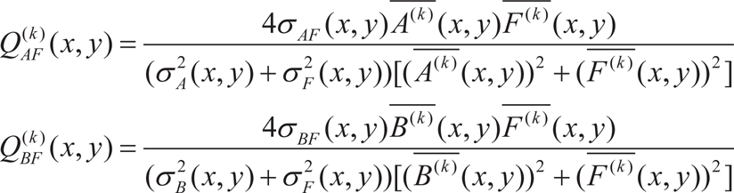
where (x, y) means every location in the whole image, and
2) Compare the value for each point: The larger value of Q indicates that at this position the initial fused image and corresponding source image are very similar. The initial decision maps Z(k) AF (x,y)Z(k) BF (x,y) can be constructed by the equation (3).
Steps of the proposed method

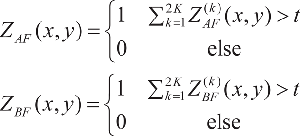
where subscript k refers to the k-th direction. 3) Vote step: Firstly, add the directional decision maps. If the sum is larger than the experience value t=k+1, this position is regarded as in focus. Both sums are represented by ZAF and ZBF.
4) Smooth step: A strategy based on morphology is performed to mitigate the thin protrusions, thin gulfs, narrow breaks, small holes in ZAF and ZBF. In multi-focus images, the area which is in focus is usually continuous and has an adequate number of pixels in the image. The smooth step is represented by Smooth(Z) and it is further divided into three sub-steps: (i) fill the holes of both {ZAF, 1-ZAF} {ZBF, 1-ZBF}; (ii) morphological image closing operation is performed to smooth the edge of the remaining areas; (iii) perform the size-filtering to {ZAF, 1-ZAF}{ZBF, 1-ZBF}.
The structural parameter of the closing operation is very important, and in the proposed method, ‘disk’ structure is chosen. If the size of the connected area is less than an experience threshold, this area will be set to 0. Because Smooth(ZAF) and 1-Smooth(1-ZBF) are in fact not identical, the overlapped pixels are set to 0. The smoothed maps are represented by ZAS F mooth and ZBFSmooth.
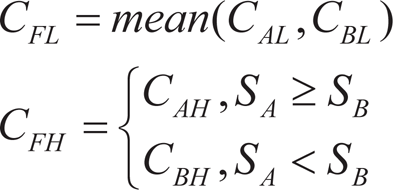
After the four steps above, the DDM is calculated. Then, the final fused image is calculated by equation (5):

where FInitial =mean(F(1)initial, F(2)initial, …, F(2K)initial and the means element multiplication.
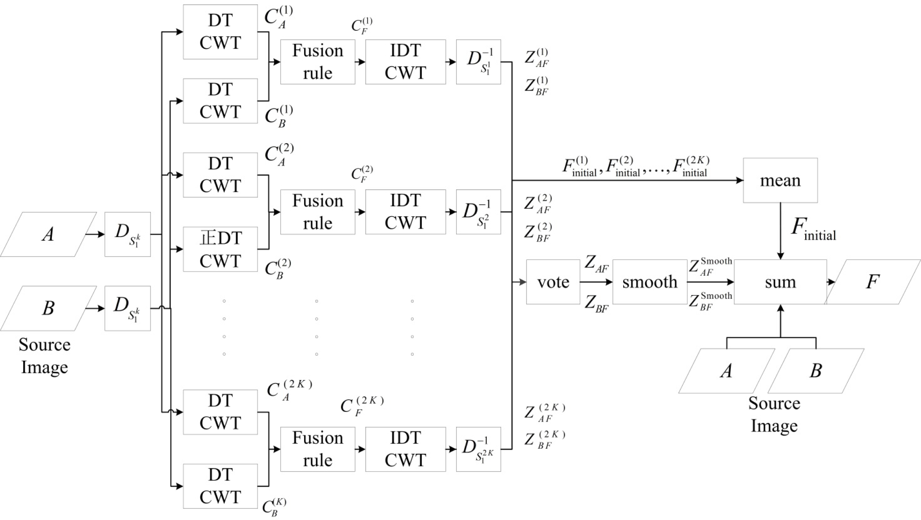
To sum up, all steps of the proposed method are given as shown in Figure 5. The steps are represented by the rectangle with the name label, and the data are represented by a parallelogram. The symbols of variables which appear in previous and current sections are marked at the arrows where they are calculated.
In this section, the evaluations of the proposed method, as well as several comparative methods, are reported. The standard source images are given in Figure 6. From left to right, they are named ‘clock', ‘lab', ‘disk’ and ‘flower', respectively. In evaluation, the number of directions is 18, which means k = 9 direction in each cone. The experience threshold in the smooth step is set to 20000.

Source images
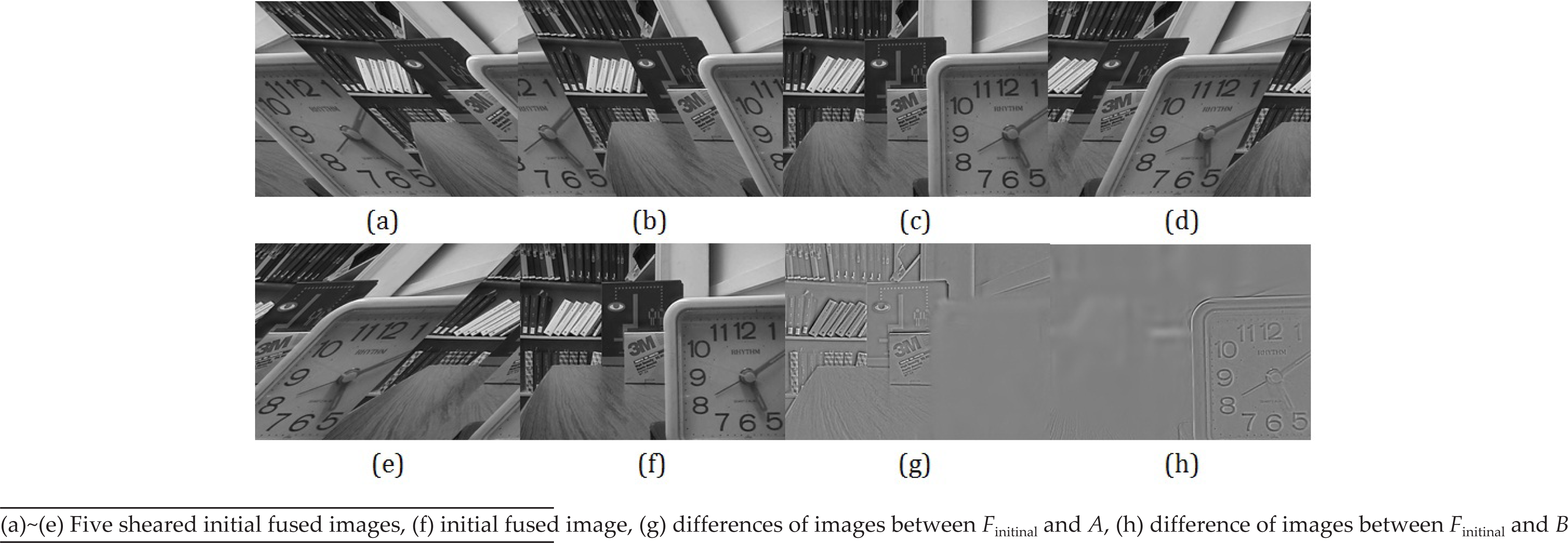
Figure 7 and Figure 8 are the initial fused images and their mean image of ‘clock’ and ‘disk'. In Figures 7 and 8, (a)–(e) are the initial fused images of five odd directions in the horizontal cone, labelled by
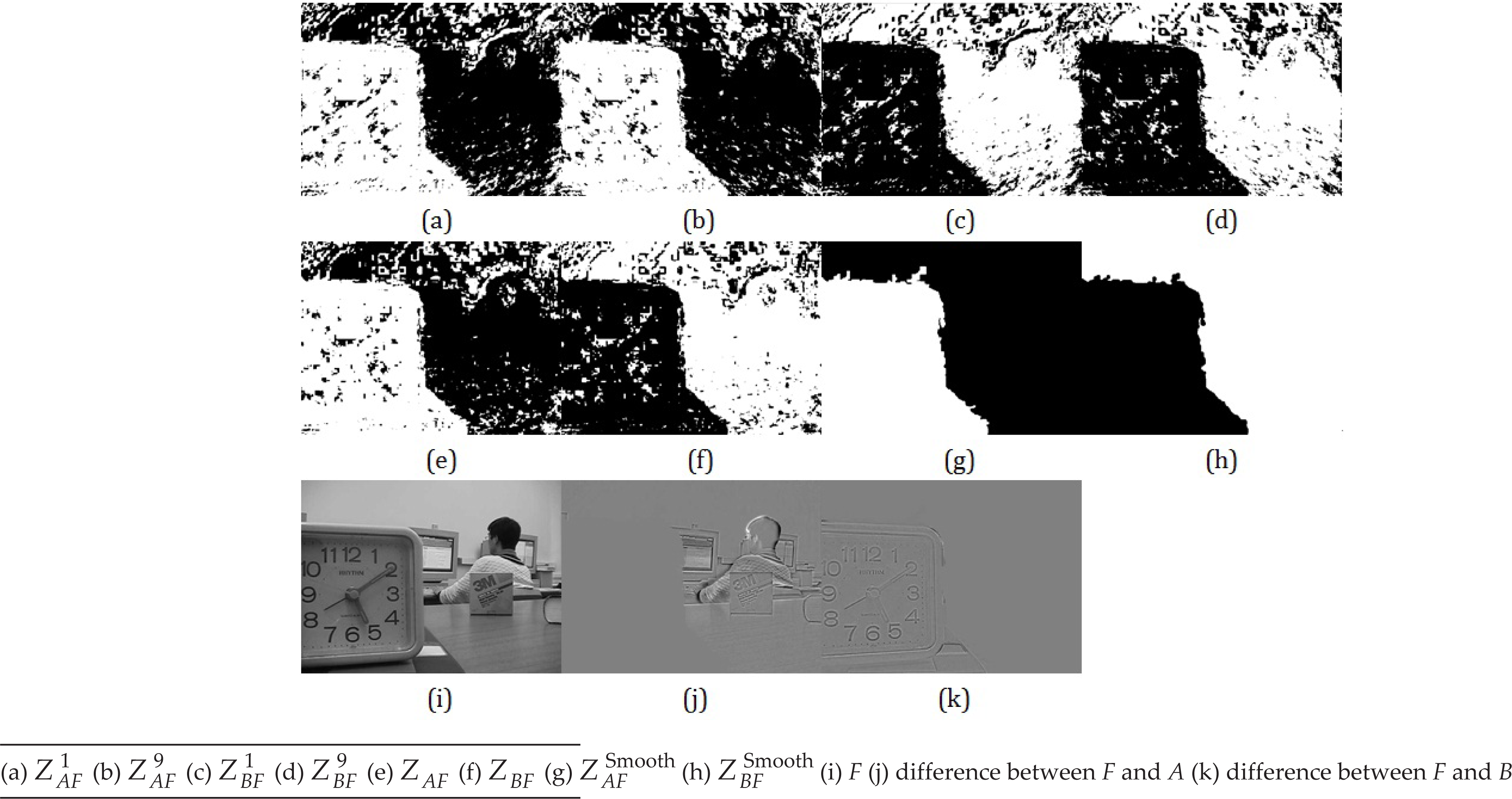
In Figure 9 and Figure 10, some key intermediate images for ‘lab’ and ‘flower’ are shown. (a) and (b) are
The quality indices are Mutual Information (MI) and QAB|F [20]. MI measures how much information in the source images would be contained in the fused images. It is defined as:

where
From Table 1 and Table 2, it can be observed that the values of MI and QAB|F of the proposed methods are better than those of both methods in [12, 13]. From both documents, we know that both methods take advantage of decision maps, and that their quality indices have reached a very extreme level. The main difference between the proposed method and these studies is the selection of MST. In the proposed method, the MST is the shift-invariant shearlet transform – DT CSST, which has the capacity for geometric analysis. So the quality indices of the proposed method can be further improved.

Initial fused image of ‘clock'
Initial fused image of ‘disk'
Key intermediate and final fused images of ‘lab'


In this paper, a multi-focus image fusion method based on the combination of DT CSST and DDM is proposed. DT CSST is approximately shift invariant. Compared with wavelet transform, which provides only one initial fused image and the decision map, the geometric analysis ability of DT CSST can provide initial fused images and DDMs in each direction. These redundancies provide more candidates with which to generate a finer decision map. Based on the parameter of local Q, instead of local RMSE or CC, the initial decision map can be generated, which may also contribute to the improvement of performance. In general, the proposed multi-focus image fusion method has better quality indices than the methods of [12, 13], which already had good perceptions. In a future study, the proposed method will be applied in the navigation of robots in noisy environments.

Key intermediate and final fused images of ‘flower'
This work is supported by the Young Scholars Development Fund of SWPU (South West Petroleum University), No. 201499010119.